Maintaining the MX2010 Cooling System Components
Maintaining the MX2010 Air Vents
Purpose
For optimum cooling, verify the condition of the air vents. Dust can clog air vents, reducing cooling system efficiency.
Action
On a regular basis, check the vents and clean them as necessary.
See Also
Maintaining the MX2010 Air Filters
Purpose
For optimum cooling, verify the condition of the air filters.
Action
On a regular basis:
Check the air filters for dust and debris. Replace the filter elements. The filter elements degrade over time, so the filter elements in use, as well as spares, must be replaced every 6 months.
CAUTION:Always keep the air filter in place while the router is operating. Because the fans are very powerful, they could pull small bits of wire or other materials into the router through the unfiltered air intake. This could damage the router components.
The shelf life of polyurethane filter varies from two years to five years depending on the storage conditions. Store in a cool, dry, and dark environment. Wrap the media in plastic and store in an environment with relative humidity between 40%- 80% and temperature between 40°F (4° C) to 90°F (32° C). Note that if the material flakes, or becomes brittle when rubbed or deformed, it is no longer usable.
See Also
Maintaining the MX2010 Air Baffle
Purpose
For optimum cooling, visually inspect the condition of the air baffle (see Figure 1 and Figure 2 ).
The air baffle is optional.
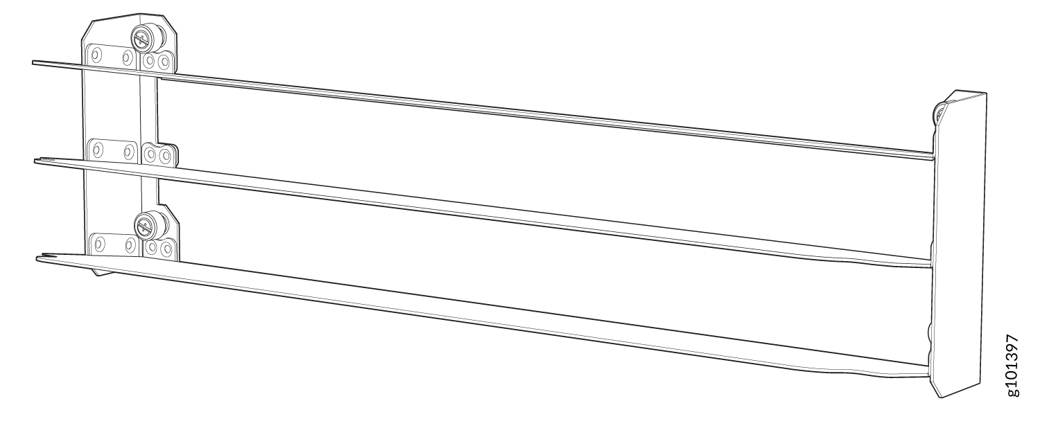
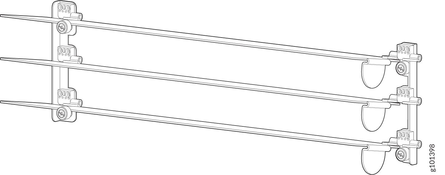
Action
Check the air baffle with adjustable louvers on a regular basis and adjust its louvers to a 10-degree upward tilt/angle to direct the exhaust air away from the router.
See Also
Maintaining the MX2010 Fan Trays
Purpose
For optimum cooling, verify the condition of the fans.
Action
Monitor the status of the fans. The fan trays each contain multiple fans that work in unison to cool the router components. If one fan fails, the host subsystem adjusts the speed of the remaining fans to maintain proper cooling. A red alarm is triggered when a fan fails, and a yellow alarm is triggered when a fan tray is removed. During normal operation, the fans in each fan tray function at normal speed.
To display the status of the cooling system, issue the
show chassis environmentcommand,show chassis environment monitoredcommand,show chassis temperature-thresholdscommand, orshow chassis fancommand.For the fan trays, the output for the
show chassis environmentcommand is similar to the following:user@host> show chassis environment Class Item Status Measurement Temp PSM 0 OK 31 degrees C / 87 degrees F PSM 1 OK 28 degrees C / 82 degrees F PSM 2 OK 28 degrees C / 82 degrees F PSM 3 OK 26 degrees C / 78 degrees F PSM 4 OK 28 degrees C / 82 degrees F PSM 5 OK 28 degrees C / 82 degrees F PSM 6 OK 27 degrees C / 80 degrees F PSM 7 OK 30 degrees C / 86 degrees F PSM 8 OK 33 degrees C / 91 degrees F PDM 0 OK PDM 1 OK CB 0 IntakeA-Zone0 OK 30 degrees C / 86 degrees F CB 0 IntakeB-Zone1 OK 32 degrees C / 89 degrees F CB 0 IntakeC-Zone0 OK 38 degrees C / 100 degrees F CB 0 ExhaustA-Zone0 OK 33 degrees C / 91 degrees F CB 0 ExhaustB-Zone1 OK 32 degrees C / 89 degrees F CB 0 TCBC-Zone0 OK 34 degrees C / 93 degrees F CB 1 IntakeA-Zone0 OK 29 degrees C / 84 degrees F CB 1 IntakeB-Zone1 OK 31 degrees C / 87 degrees F CB 1 IntakeC-Zone0 OK 33 degrees C / 91 degrees F CB 1 ExhaustA-Zone0 OK 33 degrees C / 91 degrees F CB 1 ExhaustB-Zone1 OK 31 degrees C / 87 degrees F CB 1 TCBC-Zone0 OK 34 degrees C / 93 degrees F SPMB 0 Intake OK 33 degrees C / 91 degrees F SPMB 1 Intake OK 34 degrees C / 93 degrees F Routing Engine 0 OK 38 degrees C / 100 degrees F Routing Engine 0 CPU OK 34 degrees C / 93 degrees F Routing Engine 1 OK 38 degrees C / 100 degrees F Routing Engine 1 CPU OK 34 degrees C / 93 degrees F SFB 0 Intake-Zone0 OK 45 degrees C / 113 degrees F SFB 0 Exhaust-Zone1 OK 37 degrees C / 98 degrees F SFB 0 IntakeA-Zone0 OK 35 degrees C / 95 degrees F SFB 0 IntakeB-Zone1 OK 30 degrees C / 86 degrees F SFB 0 Exhaust-Zone0 OK 40 degrees C / 104 degrees F SFB 0 SFB-XF2-Zone1 OK 47 degrees C / 116 degrees F SFB 0 SFB-XF1-Zone0 OK 50 degrees C / 122 degrees F SFB 0 SFB-XF0-Zone0 OK 57 degrees C / 134 degrees F SFB 1 Intake-Zone0 OK 52 degrees C / 125 degrees F SFB 1 Exhaust-Zone1 OK 36 degrees C / 96 degrees F SFB 1 IntakeA-Zone0 OK 39 degrees C / 102 degrees F SFB 1 IntakeB-Zone1 OK 30 degrees C / 86 degrees F SFB 1 Exhaust-Zone0 OK 43 degrees C / 109 degrees F SFB 1 SFB-XF2-Zone1 OK 46 degrees C / 114 degrees F SFB 1 SFB-XF1-Zone0 OK 52 degrees C / 125 degrees F SFB 1 SFB-XF0-Zone0 OK 63 degrees C / 145 degrees F SFB 2 Intake-Zone0 OK 34 degrees C / 93 degrees F SFB 2 Exhaust-Zone1 OK 34 degrees C / 93 degrees F SFB 2 IntakeA-Zone0 OK 29 degrees C / 84 degrees F SFB 2 IntakeB-Zone1 OK 27 degrees C / 80 degrees F SFB 2 Exhaust-Zone0 OK 32 degrees C / 89 degrees F SFB 2 SFB-XF2-Zone1 OK 44 degrees C / 111 degrees F SFB 2 SFB-XF1-Zone0 OK 41 degrees C / 105 degrees F SFB 2 SFB-XF0-Zone0 OK 43 degrees C / 109 degrees F SFB 3 Intake-Zone0 OK 34 degrees C / 93 degrees F SFB 3 Exhaust-Zone1 OK 33 degrees C / 91 degrees F SFB 3 IntakeA-Zone0 OK 28 degrees C / 82 degrees F SFB 3 IntakeB-Zone1 OK 27 degrees C / 80 degrees F SFB 3 Exhaust-Zone0 OK 32 degrees C / 89 degrees F SFB 3 SFB-XF2-Zone1 OK 44 degrees C / 111 degrees F SFB 3 SFB-XF1-Zone0 OK 41 degrees C / 105 degrees F SFB 3 SFB-XF0-Zone0 OK 45 degrees C / 113 degrees F SFB 4 Intake-Zone0 OK 33 degrees C / 91 degrees F SFB 4 Exhaust-Zone1 OK 34 degrees C / 93 degrees F SFB 4 IntakeA-Zone0 OK 27 degrees C / 80 degrees F SFB 4 IntakeB-Zone1 OK 27 degrees C / 80 degrees F SFB 4 Exhaust-Zone0 OK 31 degrees C / 87 degrees F SFB 4 SFB-XF2-Zone1 OK 45 degrees C / 113 degrees F SFB 4 SFB-XF1-Zone0 OK 40 degrees C / 104 degrees F SFB 4 SFB-XF0-Zone0 OK 42 degrees C / 107 degrees F SFB 5 Intake-Zone0 OK 33 degrees C / 91 degrees F SFB 5 Exhaust-Zone1 OK 34 degrees C / 93 degrees F SFB 5 IntakeA-Zone0 OK 28 degrees C / 82 degrees F SFB 5 IntakeB-Zone1 OK 27 degrees C / 80 degrees F SFB 5 Exhaust-Zone0 OK 31 degrees C / 87 degrees F SFB 5 SFB-XF2-Zone1 OK 44 degrees C / 111 degrees F SFB 5 SFB-XF1-Zone0 OK 40 degrees C / 104 degrees F SFB 5 SFB-XF0-Zone0 OK 42 degrees C / 107 degrees F SFB 6 Intake-Zone0 OK 34 degrees C / 93 degrees F SFB 6 Exhaust-Zone1 OK 34 degrees C / 93 degrees F SFB 6 IntakeA-Zone0 OK 28 degrees C / 82 degrees F SFB 6 IntakeB-Zone1 OK 27 degrees C / 80 degrees F SFB 6 Exhaust-Zone0 OK 31 degrees C / 87 degrees F SFB 6 SFB-XF2-Zone1 OK 46 degrees C / 114 degrees F SFB 6 SFB-XF1-Zone0 OK 39 degrees C / 102 degrees F SFB 6 SFB-XF0-Zone0 OK 42 degrees C / 107 degrees F SFB 7 Intake-Zone0 OK 34 degrees C / 93 degrees F SFB 7 Exhaust-Zone1 OK 36 degrees C / 96 degrees F SFB 7 IntakeA-Zone0 OK 28 degrees C / 82 degrees F SFB 7 IntakeB-Zone1 OK 28 degrees C / 82 degrees F SFB 7 Exhaust-Zone0 OK 32 degrees C / 89 degrees F SFB 7 SFB-XF2-Zone1 OK 46 degrees C / 114 degrees F SFB 7 SFB-XF1-Zone0 OK 42 degrees C / 107 degrees F SFB 7 SFB-XF0-Zone0 OK 43 degrees C / 109 degrees F FPC 0 Intake OK 30 degrees C / 86 degrees F FPC 0 Exhaust A OK 37 degrees C / 98 degrees F FPC 0 Exhaust B OK 35 degrees C / 95 degrees F FPC 0 QX 0 TSen OK 41 degrees C / 105 degrees F FPC 0 QX 0 Chip OK 43 degrees C / 109 degrees F FPC 0 LU 0 TCAM TSen OK 41 degrees C / 105 degrees F FPC 0 LU 0 TCAM Chip OK 43 degrees C / 109 degrees F FPC 0 LU 0 TSen OK 41 degrees C / 105 degrees F FPC 0 LU 0 Chip OK 49 degrees C / 120 degrees F FPC 0 MQ 0 TSen OK 41 degrees C / 105 degrees F FPC 0 MQ 0 Chip OK 44 degrees C / 111 degrees F FPC 1 Intake OK 29 degrees C / 84 degrees F FPC 1 Exhaust A OK 42 degrees C / 107 degrees F FPC 1 Exhaust B OK 36 degrees C / 96 degrees F FPC 1 LU 0 TCAM TSen OK 42 degrees C / 107 degrees F FPC 1 LU 0 TCAM Chip OK 50 degrees C / 122 degrees F FPC 1 LU 0 TSen OK 42 degrees C / 107 degrees F FPC 1 LU 0 Chip OK 51 degrees C / 123 degrees F FPC 1 MQ 0 TSen OK 42 degrees C / 107 degrees F FPC 1 MQ 0 Chip OK 48 degrees C / 118 degrees F FPC 1 LU 1 TCAM TSen OK 39 degrees C / 102 degrees F FPC 1 LU 1 TCAM Chip OK 42 degrees C / 107 degrees F FPC 1 LU 1 TSen OK 39 degrees C / 102 degrees F FPC 1 LU 1 Chip OK 44 degrees C / 111 degrees F FPC 1 MQ 1 TSen OK 39 degrees C / 102 degrees F FPC 1 MQ 1 Chip OK 45 degrees C / 113 degrees F FPC 2 Intake OK 32 degrees C / 89 degrees F FPC 2 Exhaust A OK 52 degrees C / 125 degrees F FPC 2 Exhaust B OK 60 degrees C / 140 degrees F FPC 2 LU 0 TSen OK 47 degrees C / 116 degrees F FPC 2 LU 0 Chip OK 61 degrees C / 141 degrees F FPC 2 LU 1 TSen OK 47 degrees C / 116 degrees F FPC 2 LU 1 Chip OK 49 degrees C / 120 degrees F FPC 2 LU 2 TSen OK 47 degrees C / 116 degrees F FPC 2 LU 2 Chip OK 54 degrees C / 129 degrees F FPC 2 LU 3 TSen OK 47 degrees C / 116 degrees F FPC 2 LU 3 Chip OK 66 degrees C / 150 degrees F FPC 2 XM 0 TSen OK 47 degrees C / 116 degrees F FPC 2 XM 0 Chip OK 59 degrees C / 138 degrees F FPC 2 XF 0 TSen OK 47 degrees C / 116 degrees F FPC 2 XF 0 Chip OK 71 degrees C / 159 degrees F FPC 2 PLX Switch TSen OK 47 degrees C / 116 degrees F FPC 2 PLX Switch Chip OK 46 degrees C / 114 degrees F FPC 9 Intake OK 32 degrees C / 89 degrees F FPC 9 Exhaust A OK 40 degrees C / 104 degrees F FPC 9 Exhaust B OK 52 degrees C / 125 degrees F FPC 9 LU 0 TSen OK 49 degrees C / 120 degrees F FPC 9 LU 0 Chip OK 51 degrees C / 123 degrees F FPC 9 LU 1 TSen OK 49 degrees C / 120 degrees F FPC 9 LU 1 Chip OK 54 degrees C / 129 degrees F FPC 9 LU 2 TSen OK 49 degrees C / 120 degrees F FPC 9 LU 2 Chip OK 43 degrees C / 109 degrees F FPC 9 LU 3 TSen OK 49 degrees C / 120 degrees F FPC 9 LU 3 Chip OK 45 degrees C / 113 degrees F FPC 9 MQ 0 TSen OK 39 degrees C / 102 degrees F FPC 9 MQ 0 Chip OK 41 degrees C / 105 degrees F FPC 9 MQ 1 TSen OK 39 degrees C / 102 degrees F FPC 9 MQ 1 Chip OK 44 degrees C / 111 degrees F FPC 9 MQ 2 TSen OK 39 degrees C / 102 degrees F FPC 9 MQ 2 Chip OK 36 degrees C / 96 degrees F FPC 9 MQ 3 TSen OK 39 degrees C / 102 degrees F FPC 9 MQ 3 Chip OK 38 degrees C / 100 degrees F Fans Fan Tray 0 Fan 1 Check Fan Tray 0 Fan 2 Check Fan Tray 0 Fan 3 Check Fan Tray 0 Fan 4 Check Fan Tray 0 Fan 5 Check Fan Tray 0 Fan 6 Check Fan Tray 1 Fan 1 OK 3840 RPM Fan Tray 1 Fan 2 OK 3840 RPM Fan Tray 1 Fan 3 OK 3840 RPM Fan Tray 1 Fan 4 OK 3840 RPM Fan Tray 1 Fan 5 OK 3840 RPM Fan Tray 1 Fan 6 OK 3960 RPM Fan Tray 2 Fan 1 OK 2520 RPM Fan Tray 2 Fan 2 OK 2520 RPM Fan Tray 2 Fan 3 OK 2520 RPM Fan Tray 2 Fan 4 OK 2520 RPM Fan Tray 2 Fan 5 OK 2520 RPM Fan Tray 2 Fan 6 OK 2520 RPM Fan Tray 3 Fan 1 OK 2640 RPM Fan Tray 3 Fan 2 OK 2640 RPM Fan Tray 3 Fan 3 OK 2640 RPM Fan Tray 3 Fan 4 OK 2640 RPM Fan Tray 3 Fan 5 OK 2760 RPM Fan Tray 3 Fan 6 OK 2640 RPM
For monitoring the temperature of specific items in the MX2010
router, the output for the show chassis environment monitored command is similar to the following:
user@host> show chassis environment monitored
Class Item                           Status     Measurement
Temp  CB 0 IntakeA-Zone0             OK         30 degrees C / 86 degrees F
      CB 0 IntakeB-Zone1             OK         33 degrees C / 91 degrees F
      CB 0 IntakeC-Zone0             OK         38 degrees C / 100 degrees F
      CB 0 ExhaustA-Zone0            OK         33 degrees C / 91 degrees F
      CB 0 ExhaustB-Zone1            OK         33 degrees C / 91 degrees F
      CB 0 TCBC-Zone0                OK         35 degrees C / 95 degrees F
      CB 1 IntakeA-Zone0             OK         30 degrees C / 86 degrees F
      CB 1 IntakeB-Zone1             OK         31 degrees C / 87 degrees F
      CB 1 IntakeC-Zone0             OK         33 degrees C / 91 degrees F
      CB 1 ExhaustA-Zone0            OK         33 degrees C / 91 degrees F
      CB 1 ExhaustB-Zone1            OK         31 degrees C / 87 degrees F
      CB 1 TCBC-Zone0                OK         34 degrees C / 93 degrees F
      SPMB 0 Intake                  OK         33 degrees C / 91 degrees F
      SPMB 1 Intake                  OK         34 degrees C / 93 degrees F
      Routing Engine 0 CPU           OK         35 degrees C / 95 degrees F
      Routing Engine 1 CPU           OK         34 degrees C / 93 degrees F
      SFB 0 Intake-Zone0             OK         45 degrees C / 113 degrees F
      SFB 0 Exhaust-Zone1            OK         38 degrees C / 100 degrees F
      SFB 0 IntakeA-Zone0            OK         35 degrees C / 95 degrees F
      SFB 0 IntakeB-Zone1            OK         31 degrees C / 87 degrees F
      SFB 0 Exhaust-Zone0            OK         41 degrees C / 105 degrees F
      SFB 0 SFB-XF2-Zone1            OK         48 degrees C / 118 degrees F
      SFB 0 SFB-XF1-Zone0            OK         50 degrees C / 122 degrees F
      SFB 0 SFB-XF0-Zone0            OK         56 degrees C / 132 degrees F
      SFB 1 Intake-Zone0             OK         53 degrees C / 127 degrees F
      SFB 1 Exhaust-Zone1            OK         37 degrees C / 98 degrees F
      SFB 1 IntakeA-Zone0            OK         40 degrees C / 104 degrees F
      SFB 1 IntakeB-Zone1            OK         31 degrees C / 87 degrees F
      SFB 1 Exhaust-Zone0            OK         44 degrees C / 111 degrees F
      SFB 1 SFB-XF2-Zone1            OK         47 degrees C / 116 degrees F
      SFB 1 SFB-XF1-Zone0            OK         52 degrees C / 125 degrees F
      SFB 1 SFB-XF0-Zone0            OK         63 degrees C / 145 degrees F
      SFB 2 Intake-Zone0             OK         34 degrees C / 93 degrees F
      SFB 2 Exhaust-Zone1            OK         34 degrees C / 93 degrees F
      SFB 2 IntakeA-Zone0            OK         29 degrees C / 84 degrees F
      SFB 2 IntakeB-Zone1            OK         27 degrees C / 80 degrees F
      SFB 2 Exhaust-Zone0            OK         32 degrees C / 89 degrees F
      SFB 2 SFB-XF2-Zone1            OK         45 degrees C / 113 degrees F
      SFB 2 SFB-XF1-Zone0            OK         40 degrees C / 104 degrees F
      SFB 2 SFB-XF0-Zone0            OK         42 degrees C / 107 degrees F
      SFB 3 Intake-Zone0             OK         33 degrees C / 91 degrees F
      SFB 3 Exhaust-Zone1            OK         34 degrees C / 93 degrees F
      SFB 3 IntakeA-Zone0            OK         28 degrees C / 82 degrees F
      SFB 3 IntakeB-Zone1            OK         27 degrees C / 80 degrees F
      SFB 3 Exhaust-Zone0            OK         32 degrees C / 89 degrees F
      SFB 3 SFB-XF2-Zone1            OK         45 degrees C / 113 degrees F
      SFB 3 SFB-XF1-Zone0            OK         39 degrees C / 102 degrees F
      SFB 3 SFB-XF0-Zone0            OK         43 degrees C / 109 degrees F
      SFB 4 Intake-Zone0             OK         33 degrees C / 91 degrees F
      SFB 4 Exhaust-Zone1            OK         34 degrees C / 93 degrees F
      SFB 4 IntakeA-Zone0            OK         27 degrees C / 80 degrees F
      SFB 4 IntakeB-Zone1            OK         27 degrees C / 80 degrees F
      SFB 4 Exhaust-Zone0            OK         31 degrees C / 87 degrees F
      SFB 4 SFB-XF2-Zone1            OK         46 degrees C / 114 degrees F
      SFB 4 SFB-XF1-Zone0            OK         39 degrees C / 102 degrees F
      SFB 4 SFB-XF0-Zone0            OK         41 degrees C / 105 degrees F
      SFB 5 Intake-Zone0             OK         32 degrees C / 89 degrees F
      SFB 5 Exhaust-Zone1            OK         34 degrees C / 93 degrees F
      SFB 5 IntakeA-Zone0            OK         28 degrees C / 82 degrees F
      SFB 5 IntakeB-Zone1            OK         27 degrees C / 80 degrees F
      SFB 5 Exhaust-Zone0            OK         31 degrees C / 87 degrees F
      SFB 5 SFB-XF2-Zone1            OK         44 degrees C / 111 degrees F
      SFB 5 SFB-XF1-Zone0            OK         39 degrees C / 102 degrees F
      SFB 5 SFB-XF0-Zone0            OK         41 degrees C / 105 degrees F
      SFB 6 Intake-Zone0             OK         33 degrees C / 91 degrees F
      SFB 6 Exhaust-Zone1            OK         34 degrees C / 93 degrees F
      SFB 6 IntakeA-Zone0            OK         27 degrees C / 80 degrees F
      SFB 6 IntakeB-Zone1            OK         27 degrees C / 80 degrees F
      SFB 6 Exhaust-Zone0            OK         31 degrees C / 87 degrees F
      SFB 6 SFB-XF2-Zone1            OK         46 degrees C / 114 degrees F
      SFB 6 SFB-XF1-Zone0            OK         38 degrees C / 100 degrees F
      SFB 6 SFB-XF0-Zone0            OK         41 degrees C / 105 degrees F
      SFB 7 Intake-Zone0             OK         33 degrees C / 91 degrees F
      SFB 7 Exhaust-Zone1            OK         35 degrees C / 95 degrees F
      SFB 7 IntakeA-Zone0            OK         28 degrees C / 82 degrees F
      SFB 7 IntakeB-Zone1            OK         28 degrees C / 82 degrees F
      SFB 7 Exhaust-Zone0            OK         32 degrees C / 89 degrees F
      SFB 7 SFB-XF2-Zone1            OK         46 degrees C / 114 degrees F
      SFB 7 SFB-XF1-Zone0            OK         40 degrees C / 104 degrees F
      SFB 7 SFB-XF0-Zone0            OK         42 degrees C / 107 degrees F
      FPC 0 Intake                   OK         30 degrees C / 86 degrees F
      FPC 0 Exhaust A                OK         37 degrees C / 98 degrees F
      FPC 0 Exhaust B                OK         35 degrees C / 95 degrees F
      FPC 0 QX 0 TSen                OK         41 degrees C / 105 degrees F
      FPC 0 QX 0 Chip                OK         43 degrees C / 109 degrees F
      FPC 0 LU 0 TCAM TSen           OK         41 degrees C / 105 degrees F
      FPC 0 LU 0 TCAM Chip           OK         42 degrees C / 107 degrees F
      FPC 0 LU 0 TSen                OK         41 degrees C / 105 degrees F
      FPC 0 LU 0 Chip                OK         49 degrees C / 120 degrees F
      FPC 0 MQ 0 TSen                OK         41 degrees C / 105 degrees F
      FPC 0 MQ 0 Chip                OK         44 degrees C / 111 degrees F
      FPC 1 Intake                   OK         28 degrees C / 82 degrees F
      FPC 1 Exhaust A                OK         42 degrees C / 107 degrees F
      FPC 1 Exhaust B                OK         37 degrees C / 98 degrees F
      FPC 1 LU 0 TCAM TSen           OK         42 degrees C / 107 degrees F
      FPC 1 LU 0 TCAM Chip           OK         49 degrees C / 120 degrees F
      FPC 1 LU 0 TSen                OK         42 degrees C / 107 degrees F
      FPC 1 LU 0 Chip                OK         49 degrees C / 120 degrees F
      FPC 1 MQ 0 TSen                OK         42 degrees C / 107 degrees F
      FPC 1 MQ 0 Chip                OK         47 degrees C / 116 degrees F
      FPC 1 LU 1 TCAM TSen           OK         38 degrees C / 100 degrees F
      FPC 1 LU 1 TCAM Chip           OK         42 degrees C / 107 degrees F
      FPC 1 LU 1 TSen                OK         38 degrees C / 100 degrees F
      FPC 1 LU 1 Chip                OK         44 degrees C / 111 degrees F
      FPC 1 MQ 1 TSen                OK         38 degrees C / 100 degrees F
      FPC 1 MQ 1 Chip                OK         44 degrees C / 111 degrees F
      FPC 2 Intake                   OK         32 degrees C / 89 degrees F
      FPC 2 Exhaust A                OK         53 degrees C / 127 degrees F
      FPC 2 Exhaust B                OK         60 degrees C / 140 degrees F
      FPC 2 LU 0 TSen                OK         47 degrees C / 116 degrees F
      FPC 2 LU 0 Chip                OK         61 degrees C / 141 degrees F
      FPC 2 LU 1 TSen                OK         47 degrees C / 116 degrees F
      FPC 2 LU 1 Chip                OK         48 degrees C / 118 degrees F
      FPC 2 LU 2 TSen                OK         47 degrees C / 116 degrees F
      FPC 2 LU 2 Chip                OK         53 degrees C / 127 degrees F
      FPC 2 LU 3 TSen                OK         47 degrees C / 116 degrees F
      FPC 2 LU 3 Chip                OK         65 degrees C / 149 degrees F
      FPC 2 XM 0 TSen                OK         47 degrees C / 116 degrees F
      FPC 2 XM 0 Chip                OK         58 degrees C / 136 degrees F
      FPC 2 XF 0 TSen                OK         47 degrees C / 116 degrees F
      FPC 2 XF 0 Chip                OK         69 degrees C / 156 degrees F
      FPC 2 PLX Switch TSen          OK         47 degrees C / 116 degrees F
      FPC 2 PLX Switch Chip          OK         45 degrees C / 113 degrees F
      FPC 9 Intake                   OK         32 degrees C / 89 degrees F
      FPC 9 Exhaust A                OK         40 degrees C / 104 degrees F
      FPC 9 Exhaust B                OK         52 degrees C / 125 degrees F
      FPC 9 LU 0 TSen                OK         49 degrees C / 120 degrees F
      FPC 9 LU 0 Chip                OK         50 degrees C / 122 degrees F
      FPC 9 LU 1 TSen                OK         49 degrees C / 120 degrees F
      FPC 9 LU 1 Chip                OK         54 degrees C / 129 degrees F
      FPC 9 LU 2 TSen                OK         49 degrees C / 120 degrees F
      FPC 9 LU 2 Chip                OK         42 degrees C / 107 degrees F
      FPC 9 LU 3 TSen                OK         49 degrees C / 120 degrees F
      FPC 9 LU 3 Chip                OK         44 degrees C / 111 degrees F
      FPC 9 MQ 0 TSen                OK         39 degrees C / 102 degrees F
      FPC 9 MQ 0 Chip                OK         40 degrees C / 104 degrees F
      FPC 9 MQ 1 TSen                OK         39 degrees C / 102 degrees F
      FPC 9 MQ 1 Chip                OK         43 degrees C / 109 degrees F
      FPC 9 MQ 2 TSen                OK         39 degrees C / 102 degrees F
      FPC 9 MQ 2 Chip                OK         36 degrees C / 96 degrees F
      FPC 9 MQ 3 TSen                OK         39 degrees C / 102 degrees F
      FPC 9 MQ 3 Chip                OK         37 degrees C / 98 degrees F
For the chassis temperature threshold settings, the output for
the show chassis temperature-thresholds command is similar
to the following:
user@host> show chassis temperature-thresholds
                   Fan speed      Yellow alarm      Red alarm      Fire Shutdown
                          (degrees C)      (degrees C)     (degrees C)      (degrees C)
Item                     Normal  High   Normal  Bad fan   Normal  Bad fan     Normal
Routing Engine 0             70    80       95       95      110      110      112
Routing Engine 1             70    80       95       95      110      110      112
CB 0 IntakeA-Zone0           60    65       78       75       85       80       95
CB 0 IntakeB-Zone1           60    65       78       75       85       80       95
CB 0 IntakeC-Zone0           60    65       78       75       85       80       95
CB 0 ExhaustA-Zone0          60    65       78       75       85       80       95
CB 0 ExhaustB-Zone1          60    65       78       75       85       80       95
CB 0 TCBC-Zone0              60    65       78       75       85       80       95
CB 1 IntakeA-Zone0           60    65       78       75       85       80       95
CB 1 IntakeB-Zone1           60    65       78       75       85       80       95
CB 1 IntakeC-Zone0           60    65       78       75       85       80       95
CB 1 ExhaustA-Zone0          60    65       78       75       85       80       95
CB 1 ExhaustB-Zone1          60    65       78       75       85       80       95
CB 1 TCBC-Zone0              60    65       78       75       85       80       95
SPMB 0 Intake                56    62       75       63       83       76       95
SFB 0 Intake-Zone0           56    62       75       63       82       70       87
SFB 0 Exhaust-Zone1          56    62       75       63       82       70       87
SFB 0 IntakeA-Zone0          56    62       75       63       82       70       87
SFB 0 IntakeB-Zone1          56    62       75       63       82       70       87
SFB 0 Exhaust-Zone0          56    62       75       63       82       70       87
SFB 0 SFB-XF2-Zone1          70    80       90       90      100      107      110
SFB 0 SFB-XF1-Zone0          70    80       90       90      100      107      110
SFB 0 SFB-XF0-Zone0          70    80       90       90      100      107      110
SFB 1 Intake-Zone0           56    62       75       63       82       70       87
SFB 1 Exhaust-Zone1          56    62       75       63       82       70       87
SFB 1 IntakeA-Zone0          56    62       75       63       82       70       87
SFB 1 IntakeB-Zone1          56    62       75       63       82       70       87
SFB 1 Exhaust-Zone0          56    62       75       63       82       70       87
SFB 1 SFB-XF2-Zone1          70    80       90       90      100      107      110
SFB 1 SFB-XF1-Zone0          70    80       90       90      100      107      110
SFB 1 SFB-XF0-Zone0          70    80       90       90      100      107      110
SFB 2 Intake-Zone0           56    62       75       63       82       70       87
SFB 2 Exhaust-Zone1          56    62       75       63       82       70       87
SFB 2 IntakeA-Zone0          56    62       75       63       82       70       87
SFB 2 IntakeB-Zone1          56    62       75       63       82       70       87
SFB 2 Exhaust-Zone0          56    62       75       63       82       70       87
SFB 2 SFB-XF2-Zone1          70    80       90       90      100      107      110
SFB 2 SFB-XF1-Zone0          70    80       90       90      100      107      110
SFB 2 SFB-XF0-Zone0          70    80       90       90      100      107      110
SFB 3 Intake-Zone0           56    62       75       63       82       70       87
SFB 3 Exhaust-Zone1          56    62       75       63       82       70       87
SFB 3 IntakeA-Zone0          56    62       75       63       82       70       87
SFB 3 IntakeB-Zone1          56    62       75       63       82       70       87
SFB 3 Exhaust-Zone0          56    62       75       63       82       70       87
SFB 3 SFB-XF2-Zone1          70    80       90       90      100      107      110
SFB 3 SFB-XF1-Zone0          70    80       90       90      100      107      110
SFB 3 SFB-XF0-Zone0          70    80       90       90      100      107      110
SFB 4 Intake-Zone0           56    62       75       63       82       70       87
SFB 4 Exhaust-Zone1          56    62       75       63       82       70       87
SFB 4 IntakeA-Zone0          56    62       75       63       82       70       87
SFB 4 IntakeB-Zone1          56    62       75       63       82       70       87
SFB 4 Exhaust-Zone0          56    62       75       63       82       70       87
SFB 4 SFB-XF2-Zone1          70    80       90       90      100      107      110
SFB 4 SFB-XF1-Zone0          70    80       90       90      100      107      110
SFB 4 SFB-XF0-Zone0          70    80       90       90      100      107      110
SFB 5 Intake-Zone0           56    62       75       63       82       70       87
SFB 5 Exhaust-Zone1          56    62       75       63       82       70       87
SFB 5 IntakeA-Zone0          56    62       75       63       82       70       87
SFB 5 IntakeB-Zone1          56    62       75       63       82       70       87
SFB 5 Exhaust-Zone0          56    62       75       63       82       70       87
SFB 5 SFB-XF2-Zone1          70    80       90       90      100      107      110
SFB 5 SFB-XF1-Zone0          70    80       90       90      100      107      110
SFB 5 SFB-XF0-Zone0          70    80       90       90      100      107      110
SFB 6 Intake-Zone0           56    62       75       63       82       70       87
SFB 6 Exhaust-Zone1          56    62       75       63       82       70       87
SFB 6 IntakeA-Zone0          56    62       75       63       82       70       87
SFB 6 IntakeB-Zone1          56    62       75       63       82       70       87
SFB 6 Exhaust-Zone0          56    62       75       63       82       70       87
SFB 6 SFB-XF2-Zone1          70    80       90       90      100      107      110
SFB 6 SFB-XF1-Zone0          70    80       90       90      100      107      110
SFB 6 SFB-XF0-Zone0          70    80       90       90      100      107      110
SFB 7 Intake-Zone0           56    62       75       63       82       70       87
SFB 7 Exhaust-Zone1          56    62       75       63       82       70       87
SFB 7 IntakeA-Zone0          56    62       75       63       82       70       87
SFB 7 IntakeB-Zone1          56    62       75       63       82       70       87
SFB 7 Exhaust-Zone0          56    62       75       63       82       70       87
SFB 7 SFB-XF2-Zone1          70    80       90       90      100      107      110
SFB 7 SFB-XF1-Zone0          70    80       90       90      100      107      110
SFB 7 SFB-XF0-Zone0          70    80       90       90      100      107      110
FPC 1                        55    60       75       65       90       80       95
FPC 2                        55    60       75       65       90       80       95
FPC 3                        55    60       75       65       90       80       95
FPC 4                        55    60       75       65       90       80       95
FPC 6                        55    60       75       65       90       80       95
For the fan trays, the output for the show chassis fan command is similar to the following:
user@host> show chassis fan
 Item                      Status   % RPM     Measurement
      Fan Tray 0 Fan 1          OK       100%      9720 RPM
      Fan Tray 0 Fan 2          OK       100%      9000 RPM
      Fan Tray 0 Fan 3          OK       100%      9720 RPM
      Fan Tray 0 Fan 4          OK       97%       8760 RPM
      Fan Tray 0 Fan 5          OK       100%      9600 RPM
      Fan Tray 0 Fan 6          OK       100%      9000 RPM
      Fan Tray 1 Fan 1          OK       100%      9120 RPM
      Fan Tray 1 Fan 2          OK       100%      9120 RPM
      Fan Tray 1 Fan 3          OK       100%      9120 RPM
      Fan Tray 1 Fan 4          OK       100%      9240 RPM
      Fan Tray 1 Fan 5          OK       100%      9240 RPM
      Fan Tray 1 Fan 6          OK       100%      9120 RPM
      Fan Tray 2 Fan 1          OK       49%       4440 RPM
      Fan Tray 2 Fan 2          OK       52%       4680 RPM
      Fan Tray 2 Fan 3          OK       52%       4680 RPM
      Fan Tray 2 Fan 4          OK       52%       4680 RPM
      Fan Tray 2 Fan 5          OK       50%       4560 RPM
      Fan Tray 2 Fan 6          OK       50%       4560 RPM
      Fan Tray 3 Fan 1          OK       50%       4560 RPM
      Fan Tray 3 Fan 2          OK       52%       4680 RPM
      Fan Tray 3 Fan 3          OK       52%       4680 RPM
      Fan Tray 3 Fan 4          OK       52%       4680 RPM
      Fan Tray 3 Fan 5          OK       50%       4560 RPM
      Fan Tray 3 Fan 6          OK       50%       4560 RPMM
Fan Tray 0, Fan Tray 1 refer to the lower rear fan trays, Fan Tray 2, and Fan Tray 3 refer to the upper rear fan trays.
Fan 1, Fan 2, Fan 3, Fan 4, Fan 5, and Fan 6 refer to the fans on the fan tray. There are six fans for each fan tray.
See Also
Maintaining the MX2010 Cooling System Zones
Purpose
For optimum router performance, verify the status of the two cooling zones (zone 0 and zone 1) of the chassis. Zone 0 consists of ten MPCs (0 through 9) and their respective MICs. Zone 0 is cooled by fan trays (0 and 1). Zone 1 consists of the CB-REs and SFBs located in the upper portion of the chassis. Zone 1 is cooled by fan trays 2 and 3. Two fan trays are at the bottom of the chassis, and two fan trays are at the top of the chassis.
Action
On a regular basis:
Check the LEDs on the craft interface for upper and lower fan trays. The green status LEDs labeled 0 and 1, for lower fan trays, and 2 and 3 for the upper fan trays light steadily when a fan tray is functioning normally.
Place your hand near the exhaust vents at the rear of the chassis to determine whether the fans are pushing air out of the chassis.
Monitor the status of the fans. During normal operation, the fans in each fan tray function at less than full speed.
The fan trays each contain multiple fans that work in unison to cool the router components. If one fan fails, the host subsystem adjusts the speed of the remaining fans to maintain proper cooling. A red alarm is triggered when a fan fails, and a yellow alarm is triggered when a fan tray is removed.
During normal operation:
The green LEDs next to the fan trays 0, 1, 2, and 3 on the craft interface light steadily when the fan tray is functioning normally for that zone.
Issue the
show chassis zonescommand to check the status of the two cooling zones. The output is similar to the following:
user@host> show chassis zones
ZONE 0 Status
    Driving FRU                 ADC 6 Exhaust
    Temperature                 63 degrees C / 145 degrees F
    Condition                   HIGH TEMP
    Num Fans Missing            0
    Num Fans Failed             0
    Fan Duty Cycle              27

ZONE 1 Status
    Driving FRU                 SFB 7 Exhaust-Zone1
    Temperature                 64 degrees C / 147 degrees F
    Condition                   WARM TEMP
    Num Fans Missing            0
    Num Fans Failed             0