Help us improve your experience.

Let us know what you think.

Do you have time for a two-minute survey?


Removing Components from the MX2010 Router Chassis Before Installing It in a Rack

Before installing the router with a pallet jack, you must first remove shipping covers and components from the chassis. With components removed, the chassis weighs approximately 324 lb (146.96 kg).

CAUTION:

The shipping covers help guide the chassis into the rack. Applying force to any other part of the chassis can cause damage.

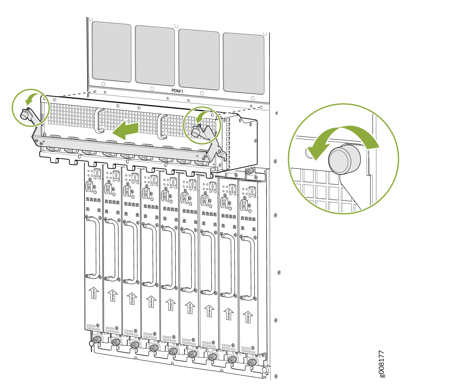
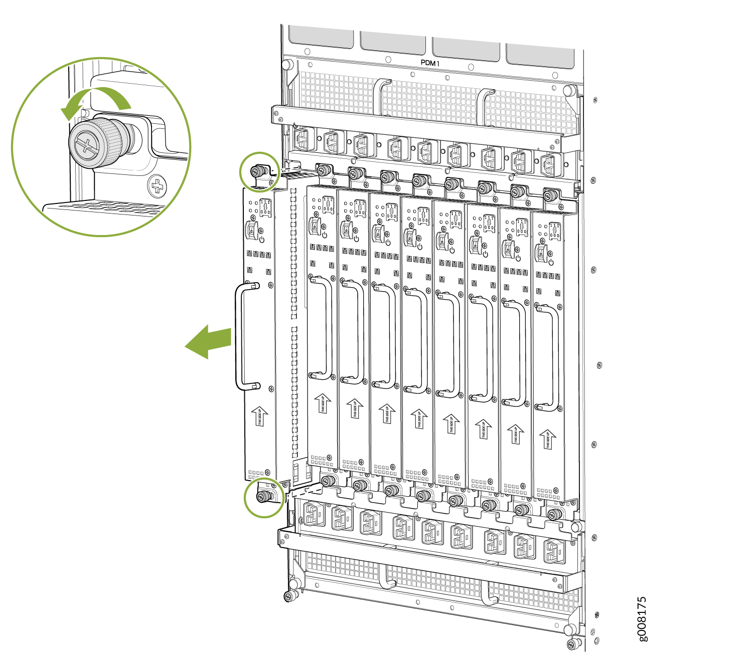
Removing the Power Distribution Modules Before Installing an MX2000 Router with a Pallet Jack

Remove the topmost PDM (PDM1) first, and then work your way downward. To remove an AC, DC, 240 V China, or universal (HVAC/HVDC) PDM (see Figure 1, Figure 2 Figure 3, and Figure 4).

  1. Attach an electrostatic discharge (ESD) grounding strap to your bare wrist, and connect the strap to an approved site ESD grounding point. See the instructions for your site.
  2. On an AC-powered router, move the AC circuit breaker from the power source to the off (O) position. On a DC-powered router, move the DC circuit breaker from the power source to the off (O) position.

    We recommend this precaution even though the PDMs are not connected to power sources.

  3. Loosen the two captive screws on the PDM faceplate. Pull the two spring-loaded locking levers away from the chassis until it stops.
    Note:

    PDM1 locking levers are pulled down to release from chassis, and PDM0 locking levers are pulled up to release from chassis.

    The PDM is extended slightly away from the chassis.

  4. With both hands, grasp the two handles and gently pull the PDM straight out of the chassis.
    CAUTION:

    Do not touch the power connector in the back of the PDM. They can get damaged.

    CAUTION:

    Do not stack PDMs on one another after you remove them. Place each component on an antistatic mat resting on a stable, flat surface.

Figure 1: Removing an AC Power Distribution Module Before Installing the MX2000 RouterRemoving an AC Power Distribution Module Before Installing the MX2000 Router
Figure 2: Removing a DC Power Distribution Module (-48 V) Before Installing the MX2000 RouterRemoving a DC Power Distribution Module (-48 V) Before Installing the MX2000 Router
Figure 3: Removing a DC Power Distribution Module (240 V China) Before Installing the MX2000 RouterRemoving a DC Power Distribution Module (240 V China) Before Installing the MX2000 Router
Figure 4: Removing a High-Voltage Universal (HVAC/HVDC) Power Distribution Module Before Installing the MX2000 RouterRemoving a High-Voltage Universal (HVAC/HVDC) Power Distribution Module Before Installing the MX2000 Router

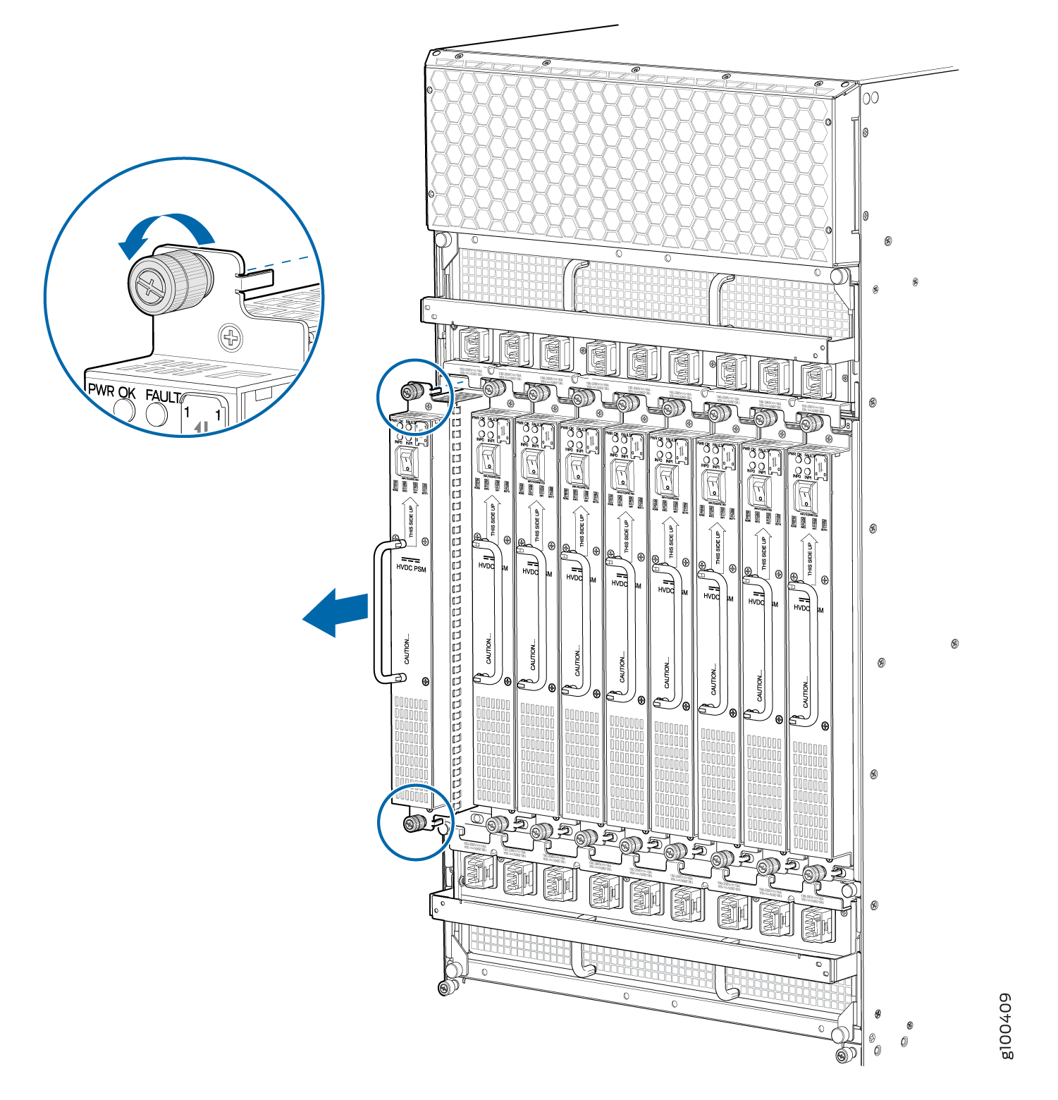
Removing the Power Supply Modules Before Installing an MX2000 Router

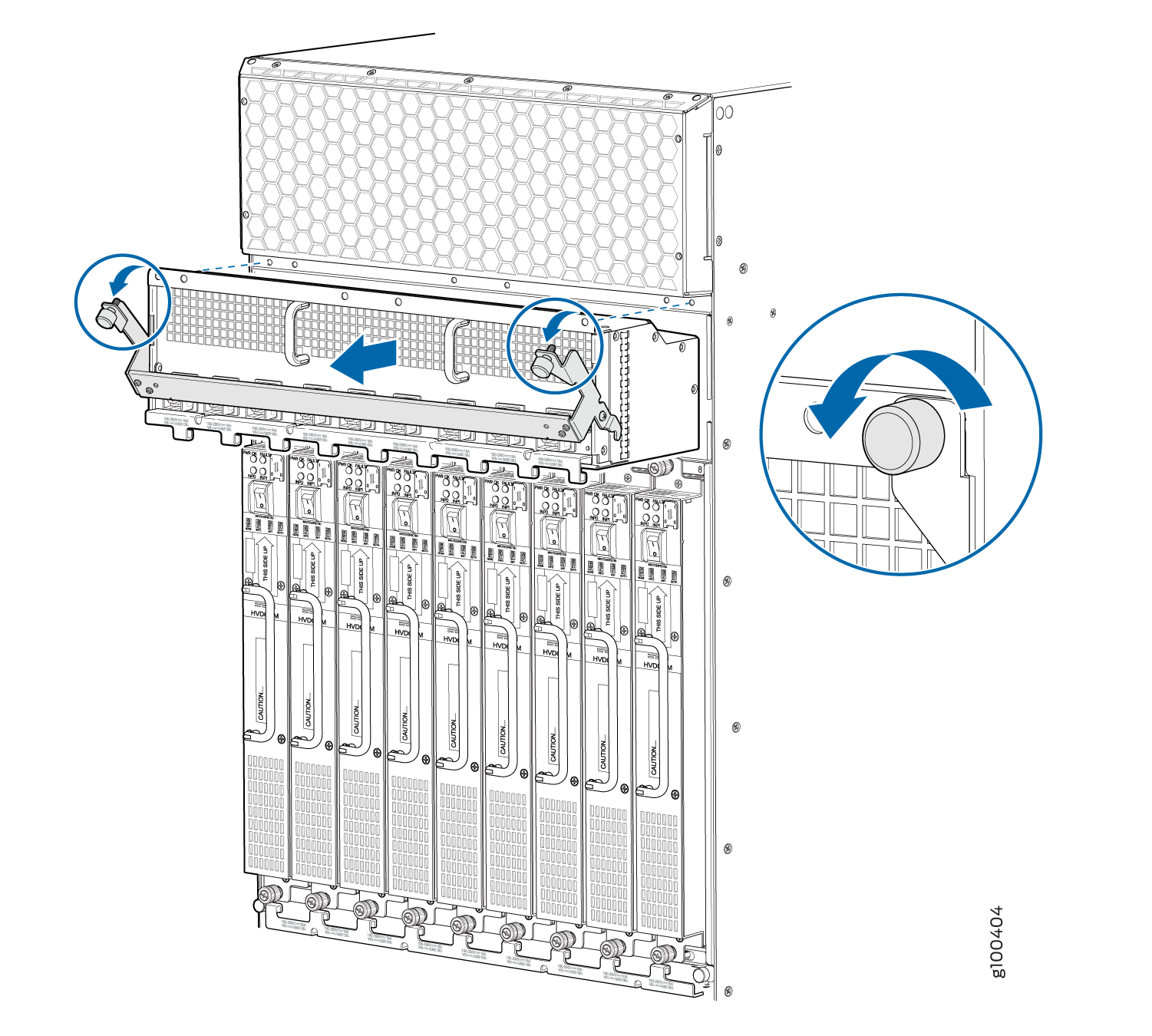
To remove the AC, DC, 240 V China, universal (HVAC/HVDC) PSMs (see Figure 5, Figure 6, Figure 7, and Figure 8):

  1. Attach an electrostatic discharge (ESD) grounding strap to your bare wrist, and connect the strap to an approved site ESD grounding point. See the instructions for your site.
  2. On an AC-powered router, move the AC power switch on each PSM to the off (O) position. On a DC-powered router, move the DC power switch on each PSM to the off (O) position.

    We recommend this even though the PSMs are not connected to power sources.

  3. Loosen the two captive screws that secure the PSM to the chassis. While grasping the handle on the PSM faceplate with one hand, use your other hand to guide the PSM.
  4. Pull the PSM straight out of the chassis.
    CAUTION:

    Do not touch the power connector on the back of the PSM. It can get damaged.

    CAUTION:

    Do not stack PSMs on one another after you remove them. Place each component on an antistatic mat resting on a stable, flat surface.

Figure 5: Removing a AC Power Supply Module Before Installing the MX2000 RouterRemoving a AC Power Supply Module Before Installing the MX2000 Router
Figure 6: Removing a DC Power Supply Module (-48 V) Before Installing the MX2000 RouterRemoving a DC Power Supply Module (-48 V) Before Installing the MX2000 Router
Figure 7: Removing a DC Power Supply Module (240 V China) Before Installing the MX2000 RouterRemoving a DC Power Supply Module (240 V China) Before Installing the MX2000 Router
Figure 8: Removing a High-Voltage Universal (HVAC/HVDC) Power Supply Module Before Installing the MX2000 RouterRemoving a High-Voltage Universal (HVAC/HVDC) Power Supply Module Before Installing the MX2000 Router

Removing the Fan Trays Before Installing an MX2010 Router

To remove the upper and lower fan trays (see Figure 9 and Figure 10):

Note:

The fan trays are interchangeable and are hot-insertable and hot-removable.

  1. Attach an electrostatic discharge (ESD) grounding strap to your bare wrist, and connect the strap to an approved site ESD grounding point. See the instructions for your site.
  2. Loosen the two captive screws on each side of the fan tray access panel and open the panel.
  3. Loosen the two captive screws on the fan tray faceplate.
  4. Press and hold the latch while simultaneously pulling the fan tray out approximately 1 to 3 in. Place one hand under the fan tray for support, while pulling the fan tray completely out of the router.
    Warning:

    The fan trays use a double-latch safety mechanism. You must continually press and hold the latch while removing the fan trays.

  5. Place each component on an antistatic mat resting on a stable, flat surface.
    CAUTION:

    Do not stack fan trays on one another after you remove them.

  6. Repeat the procedure for each fan tray.
Figure 9: Removing Upper Fan TraysRemoving Upper Fan Trays
Figure 10: Removing Lower Fan TraysRemoving Lower Fan Trays

Removing the SFBs Before Installing an MX2010 Router

To remove the SFBs (see Figure 11):

  1. Place an electrostatic bag or antistatic mat on a flat, stable surface.
  2. Attach an electrostatic discharge (ESD) grounding strap to your bare wrist, and connect the strap to an approved site ESD grounding point. See the instructions for your site.
  3. Open the ejector handles outward simultaneously to unseat the SFB.
  4. Grasp the ejector handles, and slide the SFB about halfway out of the chassis.
  5. Place one hand underneath the SFB to support it, and slide it completely out of the chassis. Place it on the antistatic mat.
    CAUTION:

    The weight of the SFB is concentrated in the back end. Be prepared to accept the full weight—up to 12 lb (5.45 kg)—as you slide the SFB out of the chassis.

    CAUTION:

    Do not stack hardware components on one another after you remove them. Place each component on an antistatic mat resting on a stable, flat surface.

  6. Repeat the procedure for each SFB.
Figure 11: Removing an SFBRemoving an SFB

Removing the MPCs and Adapter Card Before Installing an MX2010 Router

To remove an MPC with an adapter card:

  1. Have ready an antistatic mat for the MPC with an adapter card. Also, have ready rubber safety caps when removing MPCs that have optical interfaces.
  2. Attach an electrostatic discharge (ESD) grounding strap to your bare wrist, and connect the strap to an approved site ESD grounding point. See the instructions for your site.
  3. Open both the ejector handles simultaneously to unseat the both the MPC and the adapter card.
  4. Grasp the handles, and slide the MPC along with the adapter card straight out of the card cage halfway.
  5. Place one hand around the front of the MPC with the adapter card and the other hand under the MPC to support it. Slide the MPC along with the adapter card completely out of the chassis, and place it on the antistatic mat or in the electrostatic bag.
    CAUTION:

    The weight of the MPC with the adapter card is concentrated in the back end. Be prepared to accept the full weight—up to 25 lb (11.34 kg)—as you slide the MPC along with the adapter card out of the chassis.

    When the MPC along with the adapter card is out of the chassis, do not hold it by the ejector handles, bus bars, or edge connectors. They cannot support its weight.

    Do not stack MPCs with the adapter cards on top of one another after removal. Place each one individually in an electrostatic bag or on its own antistatic mat on a flat, stable surface.

Removing the MPCs Without Removing an Adapter Card Before Installing an MX2010 Router

To remove an MPC only, without removing the adapter card (see Figure 12):

  1. Have ready an antistatic mat for the MPC. Also, have ready rubber safety caps when removing MPCs that have optical interfaces.
  2. Attach an electrostatic discharge (ESD) grounding strap to your bare wrist, and connect the strap to an approved site ESD grounding point. See the instructions for your site.
  3. Simultaneously turn both the knobs counterclockwise to unseat the MPC from the adapter card.
  4. Grasp both knobs, and slide the MPC straight out of the adapter card.
  5. Place one hand around the front of the MPC and the other hand under it to support it. Slide the MPC completely out of the adapter card, and place it on the antistatic mat or in the electrostatic bag.
    CAUTION:

    The weight of the MPC is concentrated in the back end. Be prepared to accept the full weight—up to 18.35 lb (8.32 kg)—as you slide the MPC out of the adapter card.

    When the MPC is out of the adapter card, do not hold it by the knobs, bus bars, or edge connectors. They cannot support its weight.

    Do not stack MPCs on top of one another after removal. Place each one individually in an electrostatic bag or on its own antistatic mat on a flat, stable surface.

Figure 12: Removing an MPC Without Removing the Adapter CardRemoving an MPC Without Removing the Adapter Card

Removing the CB-REs Before Installing the MX2010 Router

To remove a CB-RE (see Figure 13):

  1. Have ready an antistatic mat for the CB-RE. Also have ready rubber safety caps for each SFP transceiver that uses an optical interface on the CB-RE that you are removing.
  2. Attach an electrostatic discharge (ESD) grounding strap to your bare wrist, and connect the strap to an approved site ESD grounding point. See the instructions for your site.
  3. Open both ejector handles simultaneously to unseat the CB-RE.
  4. Grasp the handles, and slide the CB-RE straight out of the card cage halfway.
  5. Place one hand around the front of the CB-RE and the other hand under it to support it. Slide the CB-RE completely out of the chassis, and place it on the antistatic mat or in the electrostatic bag.
    CAUTION:

    The weight of the CB-RE is concentrated in the back end. Be prepared to accept the full weight—up to 15 lb (6.8 kg)—as you slide the CB-RE out of the chassis.

    When the CB-RE is out of the chassis, do not hold it by the ejector handles, bus bars, or edge connectors. They cannot support its weight.

    CAUTION:

    Do not stack CB-REs on one another after you remove them. Place each component on an antistatic mat resting on a stable, flat surface.

Figure 13: Removing a CB-RERemoving a CB-RE