Help us improve your experience.

Let us know what you think.

Do you have time for a two-minute survey?


Installing the MX2008

Installing the MX2008 Mounting Hardware for a Four-Post Rack or Cabinet

Installing Cage Nuts, If Needed

Insert cage nuts, if needed, into the holes listed in Table 1 and Table 2. The hole distances are relative to the standard U division on the rack that is aligned with the bottom of the mounting shelf.

To install cage nuts in a four-post rack:

  1. On the rear side of both rack rails, insert cage nuts in the holes specified for the four-post mounting shelf. Install the cage nuts in the front of the front rail (see Table 1).
  2. On the front side of both rack rails, insert cage nuts in the holes specified for mounting the chassis. Install the cage nuts in the front of the front rail (see Table 1).
Table 1: Mounting Hole Locations for Installing the Four-Post Mounting Shelf

Hole

Distance Above U Division

6

3.25 in. (8.3 cm)

1.86 U

5

2.63 in. (6.7 cm)

1.5 U

4

2.00 in. (5.1 cm)

1.14 U

3

1.50 in. (3.8 cm)

0.86 U

2

0.88 in. (2.2 cm)

0.50 U

1

0.25 in. (0.6 cm)

0.14 U

Table 2: Mounting Hole Locations for Installing a MX2008 Chassis in a Four-Post Rack or Cabinet

Hole

Distance Above U Division

110

63.88 in. (162.2 cm)

36.50 U

101

58.63 in. (148.9 cm)

33.50 U

92

53.38 in. (135.6 cm)

30.50 U

83

48.13 in. (122.2 cm)

27.50 U

74

42.88 in. (108.9 cm)

24.50 U

65

37.63 in. (95.6 cm)

21.50 U

56

32.38 in. (82.2 cm)

18.50 U

47

27.13 in. (68.9 cm)

15.50 U

38

21.88 in. (55.6 cm)

12.50 U

29

16.63 in. (42.2 cm)

9.50 U

20

11.38 in. (28.9 cm)

6.50 U

11

6.13 in. (15.6 cm)

3.50 U

The holes in the front-mounting flanges are spaced at 3 U (5.25 in. (13.3 cm)).

Installing the Four-Post Mounting Shelf

A mounting shelf is required for installing the router in a four-post rack or cabinet. The shelf is not required for installing the router in an open-frame rack.

To install the four-post mounting shelf (see Figure 1):

  1. Slide the shelf between the rack rails, resting the bottom of the shelf on the rack rail supports. The shelf installs on the front of the rear rails, extending toward the front of the rack.
  2. Partially insert screws into the open holes in the rear flanges of the four-post mounting shelf.
    Note:

    Depending on the type of rack or cabinet you have, cage nuts might be required.

  3. Tighten all the screws completely.
  4. On the front of each front rack rail, partially insert a mounting screw into the holes in each ear of the four-post mounting shelf.
  5. Tighten all the screws completely.
    Figure 1: Installing the Mounting Hardware for a Four-Post Rack or CabinetInstalling the Mounting Hardware for a Four-Post Rack or Cabinet
    Note:
    • The two rear flanges on the four-post mounting shelf are adjustable from 24 in. (60.96 cm) through 30 in. (76.2 cm) to accommodate different types of racks rails.

    • There must be a minimum of 24-U unobstructed front-to-back usable rack space when installing the MX2008 router into a four-post rack or cabinet.

Removing the Center-Mounting Brackets

The center-mounting brackets are not used for a four-post rack, and must be removed from the chassis.

To remove the center-mounting brackets from the chassis:

  1. Loosen the screws from each bracket (see Figure 2).
  2. Remove each bracket.
    Figure 2: Center-Mounting Bracket RemovalCenter-Mounting Bracket Removal

Removing Components from the MX2008 Router Chassis Before Installing It in a Rack

Before installing the router with a pallet jack, you must first remove shipping covers and components from the chassis. With components removed, the chassis weighs approximately 324 lb (146.96 kg).

CAUTION:

The shipping covers help guide the chassis into the rack. Applying force to any other part of the chassis can cause damage.

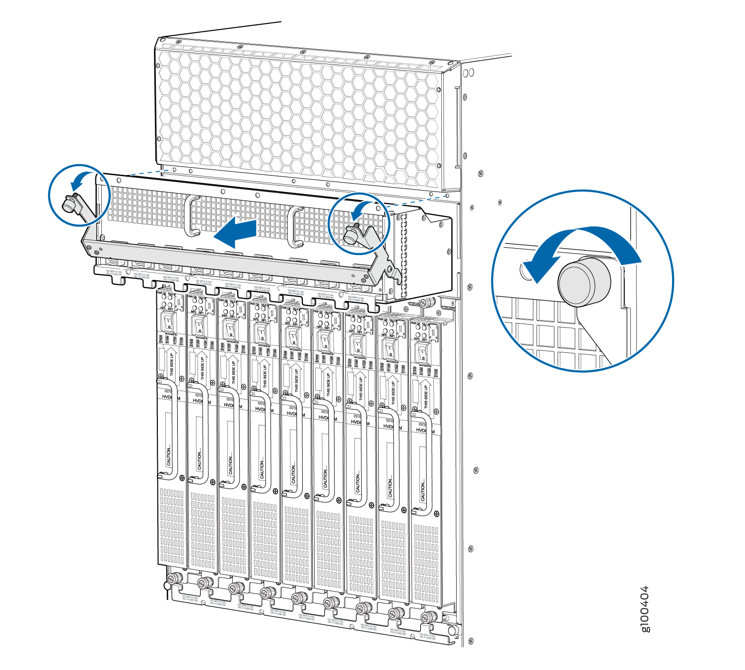
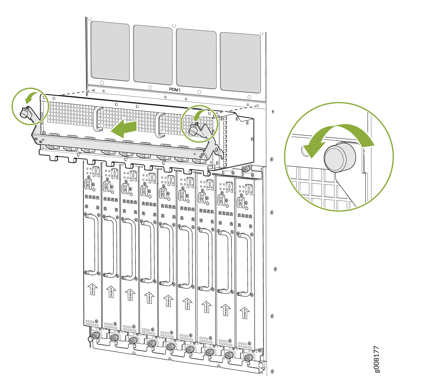
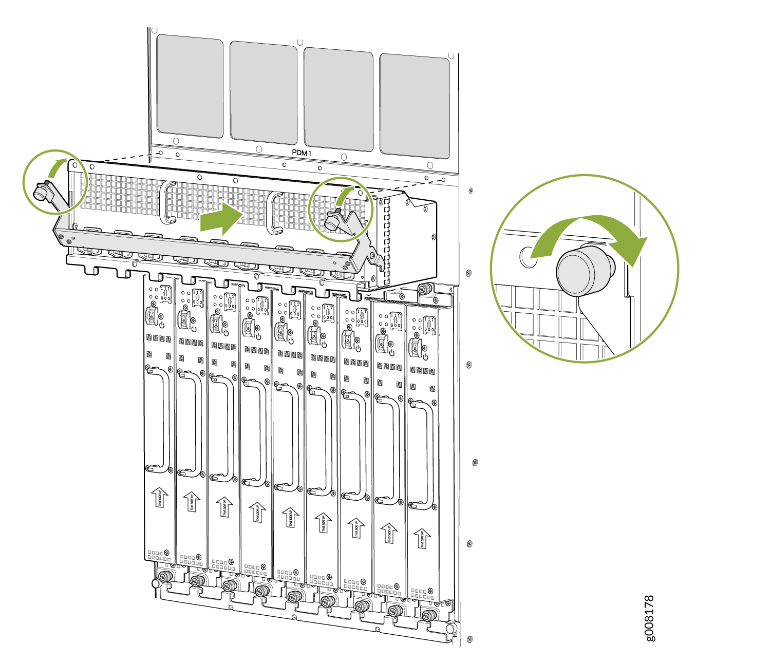
Removing the Power Distribution Modules Before Installing an MX2000 Router with a Pallet Jack

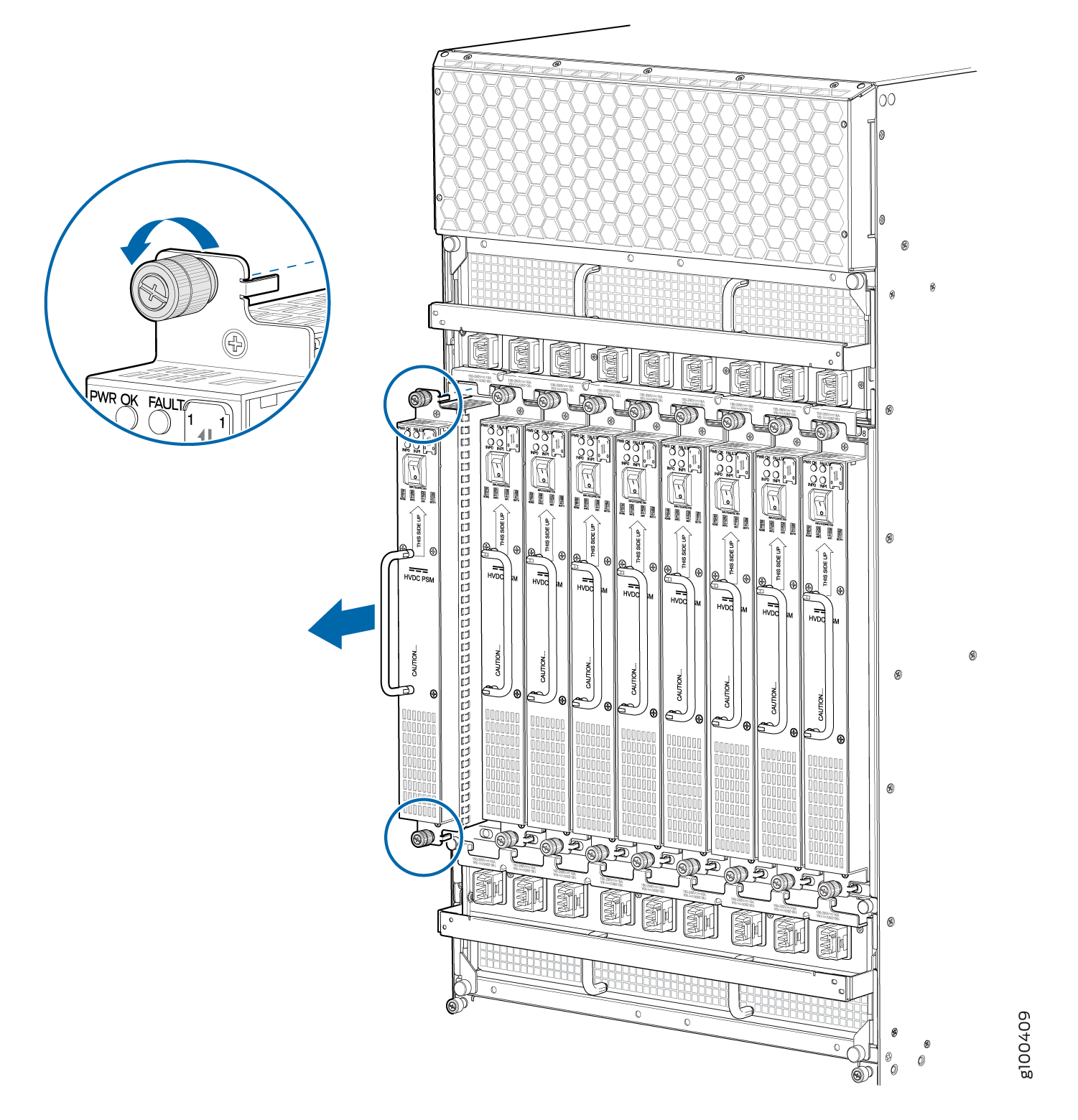
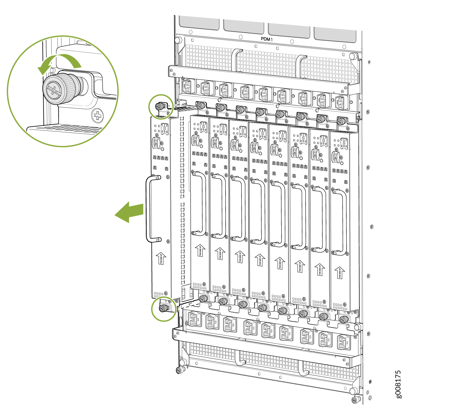
Remove the topmost PDM (PDM1) first, and then work your way downward. To remove an AC, DC, 240 V China, or universal (HVAC/HVDC) PDM (see Figure 3, Figure 4 Figure 5, and Figure 6).

  1. Attach an electrostatic discharge (ESD) grounding strap to your bare wrist, and connect the strap to an approved site ESD grounding point. See the instructions for your site.
  2. On an AC-powered router, move the AC circuit breaker from the power source to the off (O) position. On a DC-powered router, move the DC circuit breaker from the power source to the off (O) position.

    We recommend this precaution even though the PDMs are not connected to power sources.

  3. Loosen the two captive screws on the PDM faceplate. Pull the two spring-loaded locking levers away from the chassis until it stops.
    Note:

    PDM1 locking levers are pulled down to release from chassis, and PDM0 locking levers are pulled up to release from chassis.

    The PDM is extended slightly away from the chassis.

  4. With both hands, grasp the two handles and gently pull the PDM straight out of the chassis.
    CAUTION:

    Do not touch the power connector in the back of the PDM. They can get damaged.

    CAUTION:

    Do not stack PDMs on one another after you remove them. Place each component on an antistatic mat resting on a stable, flat surface.

Figure 3: Removing an AC Power Distribution Module Before Installing the MX2000 RouterRemoving an AC Power Distribution Module Before Installing the MX2000 Router
Figure 4: Removing a DC Power Distribution Module (-48 V) Before Installing the MX2000 RouterRemoving a DC Power Distribution Module (-48 V) Before Installing the MX2000 Router
Figure 5: Removing a DC Power Distribution Module (240 V China) Before Installing the MX2000 RouterRemoving a DC Power Distribution Module (240 V China) Before Installing the MX2000 Router
Figure 6: Removing a High-Voltage Universal (HVAC/HVDC) Power Distribution Module Before Installing the MX2000 RouterRemoving a High-Voltage Universal (HVAC/HVDC) Power Distribution Module Before Installing the MX2000 Router

Removing the Power Supply Modules Before Installing an MX2000 Router

To remove the AC, DC, 240 V China, universal (HVAC/HVDC) PSMs (see Figure 7, Figure 8, Figure 9, and Figure 10):

  1. Attach an electrostatic discharge (ESD) grounding strap to your bare wrist, and connect the strap to an approved site ESD grounding point. See the instructions for your site.
  2. On an AC-powered router, move the AC power switch on each PSM to the off (O) position. On a DC-powered router, move the DC power switch on each PSM to the off (O) position.

    We recommend this even though the PSMs are not connected to power sources.

  3. Loosen the two captive screws that secure the PSM to the chassis. While grasping the handle on the PSM faceplate with one hand, use your other hand to guide the PSM.
  4. Pull the PSM straight out of the chassis.
    CAUTION:

    Do not touch the power connector on the back of the PSM. It can get damaged.

    CAUTION:

    Do not stack PSMs on one another after you remove them. Place each component on an antistatic mat resting on a stable, flat surface.

Figure 7: Removing a AC Power Supply Module Before Installing the MX2000 RouterRemoving a AC Power Supply Module Before Installing the MX2000 Router
Figure 8: Removing a DC Power Supply Module (-48 V) Before Installing the MX2000 RouterRemoving a DC Power Supply Module (-48 V) Before Installing the MX2000 Router
Figure 9: Removing a DC Power Supply Module (240 V China) Before Installing the MX2000 RouterRemoving a DC Power Supply Module (240 V China) Before Installing the MX2000 Router
Figure 10: Removing a High-Voltage Universal (HVAC/HVDC) Power Supply Module Before Installing the MX2000 RouterRemoving a High-Voltage Universal (HVAC/HVDC) Power Supply Module Before Installing the MX2000 Router

Removing the Fan Trays Before Installing an MX2010 Router with a Pallet Jack

To remove the upper and lower fan tray (see Figure 11 and Figure 12):

Note:

The fan trays are interchangeable and are hot-insertable and hot-removable.

  1. Attach an electrostatic discharge (ESD) grounding strap to your bare wrist, and connect the strap to an approved site ESD grounding point. See the instructions for your site.
  2. Loosen the two captive screws on each side of the fan tray access panel and open.
  3. Loosen the two captive screws on the fan tray faceplate.
  4. While grasping the handle, press and hold the latch until the status LED turns off. Pull the fan tray out approximately 1 to 3 in.
  5. Press and hold the latch a second time to disengage fan operation. Place one hand under the fan tray for support, while pulling the fan tray completely out of the router.
    Note:

    The double latch system is a safety mechanism, so you cannot pull the fan tray out in one motion.

    CAUTION:

    Do not stack fan trays on one another after you remove them. Place each component on an antistatic mat resting on a stable, flat surface.

Figure 11: Removing Upper Fan TraysRemoving Upper Fan Trays
Warning:

Before removing a fan tray, make sure the fan blades have stopped completely.

Figure 12: Removing Lower Fan TraysRemoving Lower Fan Trays

Removing the SFBs Before Installing an MX2010 Router with a Pallet Jack

To remove the SFBs (see Figure 13):

  1. Place an electrostatic bag or antistatic mat on a flat, stable surface.
  2. Attach an electrostatic discharge (ESD) grounding strap to your bare wrist, and connect the strap to an approved site ESD grounding point. See the instructions for your site.
  3. Open the ejector handles outward simultaneously to unseat the SFB.
  4. Grasp the ejector handles, and slide the SFB about halfway out of the chassis.
  5. Place one hand underneath the SFB to support it, and slide it completely out of the chassis. Place it on the antistatic mat.
    CAUTION:

    The weight of the SFB is concentrated in the back end. Be prepared to accept the full weight—up to 12 lb (5.45 kg)—as you slide the SFB out of the chassis.

    CAUTION:

    Do not stack hardware components on one another after you remove them. Place each component on an antistatic mat resting on a stable, flat surface.

  6. Repeat the procedure for each SFB.
Figure 13: Removing an SFBRemoving an SFB

Removing the MPCs with Adapter Card Before Installing an MX2010 Router with a Pallet Jack

To remove an MPC with an adapter card (ADC):

  1. Have ready an antistatic mat for the MPC with an ADC. Also have ready rubber safety caps for each MPC using an optical interface on the MPC that you are removing.
  2. Attach an electrostatic discharge (ESD) grounding strap to your bare wrist, and connect the strap to an approved site ESD grounding point. See the instructions for your site.
  3. Open both the ejector handles simultaneously to unseat the both the MPC and the ADC.
  4. Grasp the handles, and slide the MPC along with the ADC straight out of the card cage halfway.
  5. Place one hand around the front of the MPC with the ADC and the other hand under MPC to support it. Slide the MPC along with the ADC completely out of the chassis, and place it on the antistatic mat or in the electrostatic bag.
    CAUTION:

    The weight of the MPC with the ADC is concentrated in the back end. Be prepared to accept the full weight—up to 25 lb (11.34 kg)—as you slide the MPC along with the ADC out of the chassis.

    When the MPC along with the ADC is out of the chassis, do not hold it by the ejector handles, bus bars, or edge connectors. They cannot support its weight.

    Do not stack MPCs with the ADCs on top of one another after removal. Place each one individually in an electrostatic bag or on its own antistatic mat on a flat, stable surface.

Removing the MPCs without an Adapter Card Before Installing an MX2010 Router with a Pallet Jack

To remove an MPC without an ADC (see Figure 14):

  1. Have ready an antistatic mat for the MPC. Also have ready rubber safety caps for each MPC that uses an optical interface on the MPC that you are removing.
  2. Attach an electrostatic discharge (ESD) grounding strap to your bare wrist, and connect the strap to an approved site ESD grounding point. See the instructions for your site.
  3. Simultaneously turn both the knobs counterclockwise to unseat the MPC from the ADC.
  4. Grasp both knobs, and slide the MPC straight out of the ADC.
  5. Place one hand around the front of the MPC and the other hand under it to support it. Slide the MPC completely out of the ADC, and place it on the antistatic mat or in the electrostatic bag.
    CAUTION:

    The weight of the MPC is concentrated in the back end. Be prepared to accept the full weight—up to 18.35 lb (8.32 kg)—as you slide the MPC out of the ADC.

    When the MPC is out of the ADC, do not hold it by the knobs, bus bars, or edge connectors. They cannot support its weight.

    Do not stack MPCs on top of one another after removal. Place each one individually in an electrostatic bag or on its own antistatic mat on a flat, stable surface.

Figure 14: Removing an MPC without the ADCRemoving an MPC without the ADC

Removing the CB-REs Before Installing the MX2010 Router with a Pallet Jack

To remove a CB-RE (see Figure 15):

  1. Have ready an antistatic mat for the CB-RE. Also have ready rubber safety caps for each SFP that uses an optical interface on the CB-RE that you are removing.
  2. Attach an electrostatic discharge (ESD) grounding strap to your bare wrist, and connect the strap to an approved site ESD grounding point. See the instructions for your site.
  3. Open both ejector handles simultaneously to unseat the CB-RE.
  4. Grasp the handles, and slide the CB-RE straight out of the card cage halfway.
  5. Place one hand around the front of the CB-RE and the other hand under it to support it. Slide the CB-RE completely out of the chassis, and place it on the antistatic mat or in the electrostatic bag.
    CAUTION:

    The weight of the CB-RE is concentrated in the back end. Be prepared to accept the full weight—up to 15 lb (6.8 kg)—as you slide the CB-RE out of the chassis.

    When the CB-RE is out of the chassis, do not hold it by the ejector handles, bus bars, or edge connectors. They cannot support its weight.

    CAUTION:

    Do not stack CB-REs on one another after you remove them. Place each component on an antistatic mat resting on a stable, flat surface.

Figure 15: Removing a CB-RERemoving a CB-RE

Installing an MX2008 Router Using a Pallet Jack Overview

  1. Gather the tools required to install the router. See:

    Tools Required to Install the MX2008 Router Using a Pallet Jack.

  2. Install the pallet jack attachment. See:

    Installing the Pallet Jack Attachment.

  3. Install the MX2008. See:

    Installing the MX2008 Router Using a Pallet Jack with Attachment.

Tools Required to Install the MX2008 Router Using a Pallet Jack

To install the router, you need the following tools and equipment:

  • Standard pallet jack (not provided)

  • Pallet jack attachment—MX2000-PLLT-JCK-ADPTR

  • Front component shipping covers

  • Rear component shipping covers

  • Phillips (+) screwdrivers, numbers 1, 2, and 3

  • 9/16-in. or 14-mm open-end or socket wrench to remove bracket bolts from the shipping pallet

  • ESD wrist strap

  • Antistatic mat

Installing the Pallet Jack Attachment

To install the pallet jack attachment to the pallet jack:

  1. Remove the pallet jack attachment from the shipping crate.
  2. Place the pallet jack attachment across both pallet jack legs.
  3. Using a 9/16-in. (14 mm) socket wrench, loosen and remove the eight shipping bracket support torque fasteners that are located on the top of the pallet jack attachment platform.
  4. Using a 9/16-in. (14 mm) socket wrench, loosen the torque fasteners that are located on the four adjustable pallet jack attachment brackets.
  5. Adjust the four pallet jack attachment brackets until they fit under the pallet jack legs.
  6. Tighten the torque fasteners by using a 9/16-in. (14 mm) socket wrench to secure the brackets on the pallet jack attachment to the pallet jack (see Figure 16).
    Figure 16: Installing Pallet Jack Attachment onto Pallet JackInstalling Pallet Jack Attachment onto Pallet Jack

Installing the MX2008 Router Using a Pallet Jack with Attachment

Before installing the router, you must remove all components (see Removing Components from the MX2008 Router Chassis Before Installing It in a Rack).

To install the router by using a pallet jack with attachment:

  1. Ensure that the rack is in its permanent location and is secured to the building. Ensure that the installation site allows adequate clearance for both airflow and maintenance. See Clearance Requirements for Airflow and Hardware Maintenance for the MX2008 Router.
  2. Reattach the front and rear shipping covers to the chassis to help move the router. The handles on the shipping covers are used to guide the chassis during installation.
    CAUTION:

    Do not lift the router by using the handles on the shipping covers. Use these handles only to help position the router.

  3. Place the pallet jack attachment across both legs and secure the attachment to the pallet jack.
  4. Using a four-person team to load the router onto the pallet jack, make sure it rests securely on the pallet jack attachment platform.
    Figure 17: Loading the MX2008 Router onto the Pallet JackLoading the MX2008 Router onto the Pallet Jack
    CAUTION:

    Applying force to any other parts of the chassis other than the shipping covers can damage the chassis.

  5. Attach the shipping brackets to the pallet jack attachment by using existing bracket screws.
  6. On each of the shipping brackets, partially insert screws into the hole to secure the brackets to the chassis. Tighten all screws. These brackets will prevent the chassis from tilting.
    Note:

    There must be a minimum of 24 U of usable rack space when installing the MX2008 routing into a 24-U rack.

  7. Lower the pallet jack before moving the chassis. This will help distribute the weight evenly and reduce the risk of tilting or damage to the chassis.
  8. Using the pallet jack, position the router in front of the rack or cabinet, centering it in front of the rack.
    Note:

    If you are installing the MX2008 router into a network cabinet, make sure that no hardware, device, rack, or cabinet component obstructs the 24-U rack space from access during installation.

  9. Using the pallet jack, lift the chassis approximately 0.75 in. (1.9 cm) above the surface of the mounting shelf (four-post rack) or bottom opening of the rack (open-frame rack), and position it as close as possible.
    Note:

    Due to the short lift capability of the pallet jack, we recommended that you install the router on the bottom of the rack.

  10. Remove the shipping brackets that are attached to the pallet jack attachment and chassis, and set them aside.
  11. Grasp the handles on the shipping covers and carefully slide the router into the rack (see and Figure 18 and Figure 19). If you are installing the router into a four-post rack, continue sliding the router onto the mounting shelf so that the bottom of the chassis and the mounting shelf overlap by approximately 2 inches.
    Figure 18: Loading the MX2008 Router into the RackLoading the MX2008 Router into the Rack
    Figure 19: Installing the MX2008 Router on an Open-Frame RackInstalling the MX2008 Router on an Open-Frame Rack
  12. With four people pushing on the front-mounting flanges, slide the router until the center-mounting brackets (open-frame racks) or front-mounting flanges (four-post racks) contact the rack rails. In a four-post rack, the mounting shelf ensures that the holes in the front-mounting flanges of the chassis align with the holes in the rack rails.
  13. Move the pallet jack away from the rack.
  14. Insert twelve mounting screws (six on each side) into the mounting holes to secure the router to the rack.
  15. Visually inspect the alignment of the router. If the router is installed properly in the rack, all the mounting screws on one side of the rack should be aligned with the mounting screws on the opposite side, and the router should be level.

Installing an MX2008 Router Using a Router Transport Kit Overview

Tools Required to Install the MX2008 Router Using a Router Transport Kit

To install the router by using a router transport kit, you need the following tools and equipment:

  • Router transport kit (model number MX2K-TRNSPRT-KIT)

  • Front component shipping cover

  • Rear component shipping cover

  • Phillips (+) screwdrivers, numbers 1, 2, and 3

  • 1/2-in. (12.7 mm) drive ratchet

  • 1/4-in. (6.35 mm) torque-controlled driver or socket wrench to tighten the nuts on the router transport kit

  • 1-1/8-in. (28.57 mm) torque-controlled driver or socket wrench to tighten the router transport kit winch mechanism

  • 9/16-in. or 14-mm open-end or socket wrench with extension to remove bracket bolts from the shipping pallet

  • Electrostatic discharge wrist strap

  • Antistatic mat

Note:

The router transport kit does not come with the router. You need to purchase the router transport kit from Juniper Networks. Using the router mounting kit for installing the MX2008 is optional.

Installing the Router Transport Kit on the MX2008

Note:

The router transport kit is optional and can be purchased from Juniper Networks.

The router transport kit includes the following components:

  • Router transport platform

  • Router transport left and right mounting plates with adjustable wheel assembly

  • Router winch mount with winch strap plate

To install the router transport kit:

  1. Remove the router transport kit from the shipping crate (see Unpacking the MX2008 Router Transport Kit).
    Note:

    The router transport kit weighs approximately 138.5 lb (62.82 kg).

  2. Remove the winch strap plate that is secured to the winch mount by using a 9/16-in. (14 mm) socket wrench, and set the plate aside.
  3. Using a number 3 Phillips screwdriver, loosen the captive screws that secure the winch mount to the router transport kit, and set the mount aside.
  4. Using a number 3 Phillips screwdriver, loosen the captive screws that secure the router transport mounting plate and wheel assembly (left and right) to the router transport platform, and set them aside (see Figure 20).
    Figure 20: Preparing the Router Transport Kit for InstallationPreparing the Router Transport Kit for Installation
  5. Remove the four shipping brackets that secure the router to the shipping crate platform using a 9/16-in. (14 mm) socket wrench, and a number 2 Phillips screwdriver, and set the brackets aside.
  6. Align the left router transport mounting plate and wheel assembly (indicated by left arrow) with the holes on the left side of the chassis (see Figure 21).
  7. Using a number 3 Phillips screwdriver, tighten the captive screws to secure the router transport mounting plate and wheel assembly to the chassis.
  8. Align the right router transport mounting plate and wheel assembly (indicated by right arrow) with the holes on the right side of the chassis (see Figure 21).
  9. Using a number 3 Phillips screwdriver, tighten the captive screws to secure the router transport mounting plate and wheel assembly to the chassis.
    Figure 21: Installing the Router Transport Kit onto the MX2008 RouterInstalling the Router Transport Kit onto the MX2008 Router

Securing the MX2008 Router to the Router Transport Platform

To secure the router to the router transport platform:

  1. Ensure that the rack is in its permanent location and is secured to the building. Ensure that the installation site allows adequate clearance for router transport kit turn ratios, airflow, and maintenance.
  2. Using a two-person team on either side of the chassis, turn the handles on the router transport four or five times until the chassis is raised approximately 1 in. (2.54 cm), making sure that the chassis is level (see Figure 22).
    Note:

    An empty MX2008 weighs approximately 324 lb (146.96 kg).

    Figure 22: Securing the Crate Door to the Shipping Crate PlatformSecuring the Crate Door to the Shipping Crate Platform
    Note:

    The router transport kit is equipped with four T-shaped levels on top of each of the four router transport mounting brackets. Make sure the bubbles within the T-shaped levels are between the lines, indicating the chassis is level.

    CAUTION:

    Do not raise the chassis above 1 in. (2.54 cm). This ensures that the router will not tilt when transporting, which can result in injury or damage to the router.

  3. Turn the four wheels on the router transport kit toward the rear of the chassis.
  4. Grasping the handles on the shipping covers, carefully guide the chassis down the crate ramp to the rack location.
    Warning:

    Do not push or pull the router fast during transporting. Using excessive speed can cause the wheels to turn abruptly and tilt the router over.

    CAUTION:

    Do not lift the router by using the handles on the shipping covers. Use these handles only to help position the router.

  5. Position the router transport platform directly under the router, aligning the router transport platform with the bottom of the chassis by adjusting the four leveling mounts.
    Note:

    The router transport platform height can be adjusted between 0.25 in. (0.6 cm) and a maximum of 4 in. (10.16 cm).

  6. Secure the router transport platform to the router transport mounting plates by using the four latch locks (see Figure 23).
    Figure 23: Securing the Router Transport PlatformSecuring the Router Transport Platform

Using the Router Transport Kit to Install the MX2008 Router in a Four-Post Rack

Because of the router's size and weight—up to 985 lb (446.79 kg) depending on the configuration—we recommend that you use a router transport kit to install the router. The router transport kit does not come with the router. You need to purchase the router transport kit from Juniper Networks. Using the router mounting kit for installing the MX2008 is optional.

Note:

Four people are needed to install the router into a rack.

CAUTION:

Before front mounting the router in a rack, have a qualified technician verify that the rack is strong enough to support the router's weight and is adequately supported at the installation site.

To install the router in a four-post rack by using the router transport kit:

  1. Install the winch strap plate to the rear of the router by tightening the four captive screws (see Figure 24).
    Figure 24: Installing Winch Strap Plate (Four-Post Rack)Installing Winch Strap Plate (Four-Post Rack)
  2. Using a four-person team, transport the router to the rack installation location and center it in front of the mounting shelf.
    Note:
    • A minimum of 38 in. (96.5 cm) of clearance is required to roll the chassis sideways.

    • A minimum of 42 in. (106.7 cm) of circular space is required to rotate the chassis.

    • The router transport kit handles can be removed to accommodate aisle width.

  3. Install the winch mount bracket to the rear rack rails by using the six captive screws, and tighten the screws (see Figure 25).
    Figure 25: Installing Winch Mount Bracket to Rack RailsInstalling Winch Mount Bracket to Rack Rails
  4. Adjust the height of the router by turning the handles clockwise until the router transport platform is aligned with the surface of the mounting shelf and slightly higher than the mounting shelf (see Figure 26).
    Note:

    Make sure the bubbles within the T-shaped levels are between the lines, indicating that the router is level.

  5. Adjust the four leveling mounts on the router transport platform until all four leveling mounts rest firmly on the ground (see Figure 26).
    Figure 26: Align the MX2008 Router with Rack Mounting ShelfAlign the MX2008 Router with Rack Mounting Shelf
  6. Unlock the four toggle latches that secure the router transport platform to the router transport mounting plate and wheel assembly.
  7. Lift the wheels up by turning the handles counterclockwise so that the weight of the router is on the router transport platform.
  8. Using a number 3 Phillips screwdriver, loosen the captive screws that secure the router transport mounting plates and wheel assembly to the chassis, and set them aside (see Figure 27).
    Figure 27: Remove Router Transport Mounting Plate and Wheel AssemblyRemove Router Transport Mounting Plate and Wheel Assembly
  9. Attach the winch strap to the winch strap plate at the rear of the router (see Figure 28).
    Figure 28: Attaching Winch Strap to Winch Strap PlateAttaching Winch Strap to Winch Strap Plate
  10. Attach a 1-1/8 in. (28.57 mm) socket wrench to the winch mechanism and turn clockwise to start pulling the chassis into the rack (see Figure 29).
    Figure 29: Pulling the MX2008 into the Rack Pulling the MX2008 into the Rack
    Note:
    • A four-person team is needed to carefully guide the router into the rack while operating the winch.

    • If the router is not pulled all the way into the rack by the winch mechanism, grasp the handles on the shipping covers and carefully slide the router onto the mounting shelf until the front-mounting flanges contact the rack rails. You must remove the winch bracket to perform this procedure.

    • There must be a minimum of 24-U of usable rack space when installing the MX2008 into a 24-U rack.

  11. Remove the router transport platform, and set the platform aside.
  12. Remove the winch mount and winch strap plate, and set them aside.
  13. Insert twelve mounting screws (six on each side) into the mounting holes to secure the router to the rack.
  14. Visually inspect the alignment of the router. To verify that the router is installed properly in the rack, see that all the mounting screws on one side of the rack are aligned with the mounting screws on the opposite side and the router is level.
  15. Reassemble the router transport kit, and set it aside.

Using the Router Transport Kit to Install the MX2008 Router in an Open-Frame Rack

Note:

Four persons are needed to install the router into a rack.

CAUTION:

Before front-mounting the router in a rack, have a qualified technician verify that the rack is strong enough to support the router's weight and is adequately supported at the installation site.

To install the MX2008 in an open-frame rack by using a router transport kit:

  1. Using the router transport platform, position the router in front of the rack or cabinet, centering it in front of the rack.
  2. Using a four-person team, transport the router to the rack installation location and center it in front of the rack.
    Note:
    • A minimum of 38 in. (96.5 cm) of clearance is required to roll the chassis sideways.

    • A minimum of 42 in. (106.7 cm) of circular space is required to rotate the chassis.

    • The router transport kit handles can be removed to accommodate aisle width.

  3. Adjust the height of the router by turning the handles clockwise until the router transport platform is approximately 0.75 in. above the bottom of the rack opening (see Figure 30).
    Note:
    • Because of the short lift capability of the router transport kit, we recommend that you install the router on the bottom of the rack.

    • Make sure that the bubbles within the T-shaped levels are between the lines, indicating that the router is level.

  4. Adjust the four leveling mounts on the router transport platform until all four leveling mounts rest firmly on the ground (see Figure 30).
    Figure 30: Aligning the MX2008 Router with the RackAligning the MX2008 Router with the Rack
  5. Unlock the four toggle latches that secure the router transport platform to the router transport mounting plate and wheel assembly.
  6. Lift the wheels up by turning the handles counterclockwise so that the weight of the router is on the router transport platform.
  7. Using a number 3 Phillips screwdriver, loosen the captive screws that secure the router transport mounting plates and wheel assembly to the chassis, and set them aside (see Figure 31).
    Figure 31: Removing Router Transport Mounting Plate and Wheel AssemblyRemoving Router Transport Mounting Plate and Wheel Assembly
  8. Grasping the handles on the shipping covers, carefully slide the router into the rack until the center-mounting brackets contact the rack rails (see Figure 32).
    Figure 32: Sliding the MX2008 into the Open-Frame RackSliding the MX2008 into the Open-Frame Rack
    Note:
    • A four-person team is needed to carefully guide the router into the rack.

    • There must be a minimum of 24-U of usable rack space when installing the MX2008 into a 24-U rack.

  9. Remove the router transport platform, and set the platform aside.
  10. Insert twelve mounting screws (six on each side) into the mounting holes to secure the router to the rack.
  11. Visually inspect the alignment of the router. To verify that the router is installed properly in the rack, see that all the mounting screws on one side of the rack are aligned with the mounting screws on the opposite side and the router is level.
  12. Reassemble the router transport kit, and set aside for future use.

Reinstalling Components in the MX2008 Router After Initially Installing the Router in a Rack

After the router is installed in the rack, remove the shipping covers, and reinstall the removed components before booting and configuring the router. You reinstall components first in the rear of the chassis, and then in the front:

Reinstalling the Power Distribution Modules After Installing the MX2000 Router with a Pallet Jack

To reinstall the AC, DC, 240 V China, or universal PDMs, follow this procedure for each PDM (see Figure 33 and Figure 34):

  1. Attach an electrostatic discharge (ESD) grounding strap to your bare wrist, and connect the strap to one of the ESD points on the chassis.
  2. For a AC-powered router, move the AC circuit breaker on the power source to the off (O) position. For a DC-powered router, move the DC circuit breaker on the power source to the off (O) position. We recommend this precaution even though the PDMs are not connected to power sources.
  3. Take each PDM to be installed out of its electrostatic bag, and identify the slot on the PDM where it will be connected.
  4. Turn the DC power switch to the off (O) position on all PSMs that are associated with the PDM being reinstalled.
  5. Using both hands, grasp the two handles and slide the PDM partway into the chassis.
  6. Align both locking levers with the openings in the chassis, and simultaneously close them to fully seat the PDM.
  7. Tighten both captive screws on the locking levers.
    Note:

    The three-phase delta or wye AC PDM terminal blocks will be flipped depending on which slot the PDMs gets plugged into.

Figure 33: Reinstalling an AC Power Distribution ModuleReinstalling an AC Power Distribution Module
Figure 34: Reinstalling a DC Power Distribution Module (-48 V)Reinstalling a DC Power Distribution Module (-48 V)
Note:

For the DC-powered router, make sure the switch is set to 60 A, or 80 A to match the DC circuit input feed.

Figure 35: Reinstalling a DC Power Distribution Module (240 V China)Reinstalling a DC Power Distribution Module (240 V China)
Figure 36: Reinstalling a High-Voltage Universal (HVAC/HVDC) Power Distribution Module Reinstalling a High-Voltage Universal (HVAC/HVDC) Power Distribution Module

Reinstalling the Power Supply Modules After Installing the MX2000 Router with a Pallet Jack

To reinstall the AC, DC, 240 V China, or universal PDMs, follow this procedure for each PSM (see Figure 37 and Figure 38) which shows the installation of the AC or DC PSM.

  1. Remove the PSM to be installed out of the ESD bag, and identify the slot where it will be installed; 0 through 8 .
    Note:

    The MX2000 PSMs can be installed in any order in the chassis.

  2. For an AC-powered router, move the AC power switch on the PSMs to the off (O) position. For a DC-powered router, move the DC power switch on the PSMs to the off (O) position.
  3. While holding the handle, using both hands, slide the PSM straight in until the PSM is fully seated into the chassis slot.
  4. The PSM faceplate should be flush with adjacent PSMs.
Figure 37: Reinstalling an AC Power Supply ModuleReinstalling an AC Power Supply Module
Figure 38: Reinstalling a DC Power Supply Module (-48 V)Reinstalling a DC Power Supply Module (-48 V)
Figure 39: Reinstalling a DC Power Supply Module (240 V China)Reinstalling a DC Power Supply Module (240 V China)
Figure 40: Reinstalling a High-Voltage Universal (HVAC/HVDC)Reinstalling a High-Voltage Universal (HVAC/HVDC)

Reinstalling the Fan Trays After Installing the MX2000 Router with a Pallet Jack

To reinstall the upper or lower fan trays, (see Figure 41 and Figure 42):

  1. Loosen the two captive screws on each side of the fan tray access panel, and open.
  2. Take each fan tray to be installed out of its electrostatic bag, and identify the slot on the fan tray where it will be connected.
  3. While grasping the handle, place one hand under the fan tray for support, and align it into the slot.
  4. Press and hold the latch while guiding the fan tray half way in until it stops.
    Note:

    The fan tray has a safety mechanism so that the fan tray cannot be removed in one motion.

  5. Press and hold the latch a second time while inserting the fan tray completely into the router.
  6. Tighten the two captive screws on the fan tray faceplate.
  7. Close the fan tray access panel, and tighten the captive screws to secure it in place.
  8. Reinstall the remaining components into the router.
Figure 41: Installing Upper Fan TraysInstalling Upper Fan Trays
Figure 42: Installing Lower Fan TraysInstalling Lower Fan Trays

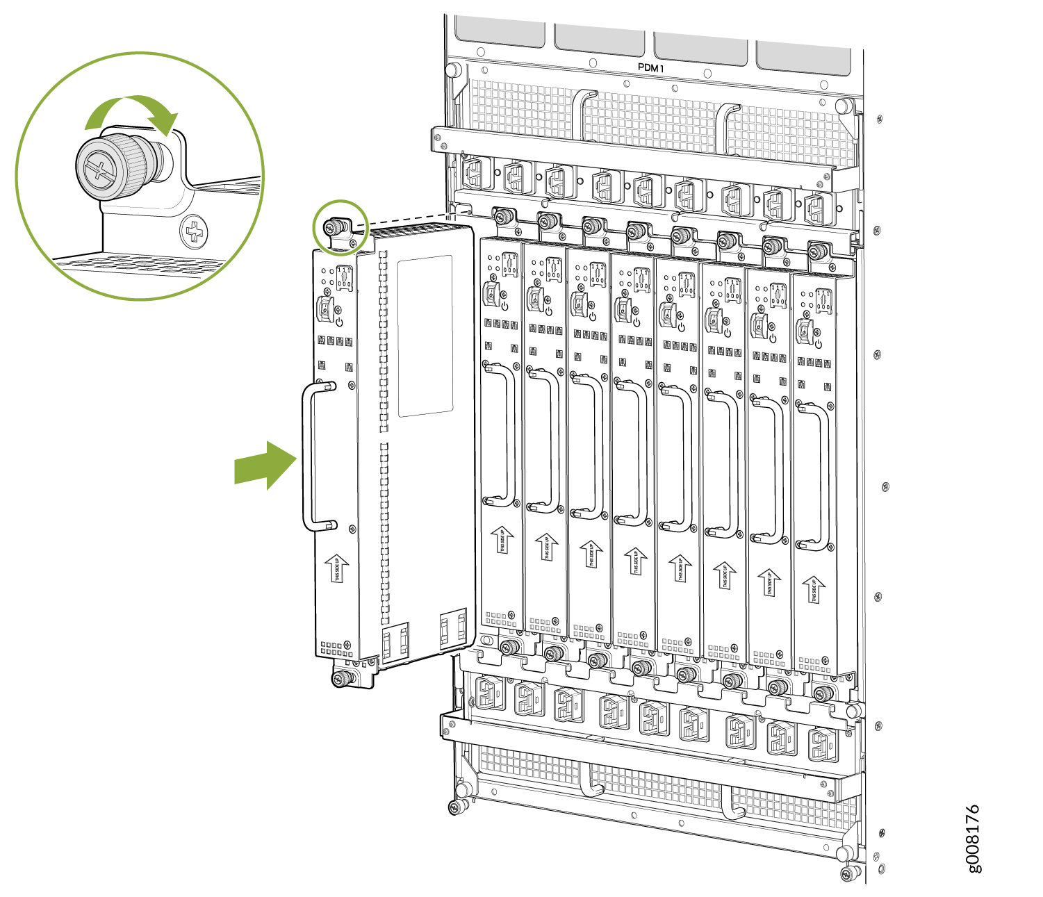
Reinstalling the SFBs After Installing the MX2010 Router with a Pallet Jack

To reinstall an SFB (see Figure 43):

CAUTION:

Before removing or replacing an SFB, ensure that the ejector handles are stored horizontally and pressed toward the center of the SFB.

  1. Attach an electrostatic discharge (ESD) grounding strap to your bare wrist, and connect the strap to one of the ESD points on the chassis.
  2. Take each SFB to be installed out of its electrostatic bag, and identify the slot on the SFB where it will be connected.
  3. Carefully align the sides of the SFB with the guides inside the chassis.
  4. Slide the SFB into the chassis until you feel resistance, carefully ensuring that it is correctly aligned.
  5. Grasp both ejector handles, and gently close them inward simultaneously until the SFB is fully seated.
  6. Place the ejector handles in their proper position, vertically and toward the center of the board.
    CAUTION:

    If one of the SFBs fails, do not remove the failed SFB until you have a replacement or blank panel to install.

Figure 43: Reinstalling an SFBReinstalling an SFB

Reinstalling the Adapter Card After Installing the MX2010 Router with a Pallet Jack

To reinstall an ADC (see Figure 44):

  1. Attach an electrostatic discharge (ESD) grounding strap to your bare wrist, and connect the strap to one of the ESD points on the chassis.
  2. Take each ADC to be installed out of its electrostatic bag, and identify the slot where it will be installed.
  3. Locate the slot in the card cage in which you plan to install the ADC.
  4. Ensure that the ADC is right-side up, with the text on the faceplate facing upward.
  5. Lift the ADC into place, and carefully align first the bottom, then the top of the ADC with the guides inside the card cage.
  6. Slide the ADC all the way into the card cage until you feel resistance.
  7. Grasp both ejector handles, and gently close them inward simultaneously until the ADC is fully seated.
Figure 44: Reinstalling an ADC Reinstalling an ADC

Reinstalling the MPCs After Installing the MX2010 Router with a Pallet Jack

To reinstall an MPC (see Figure 45):

  1. Attach an electrostatic discharge (ESD) grounding strap to your bare wrist, and connect the strap to one of the ESD points on the chassis.
  2. Take each MPC to be installed out of its electrostatic bag, and identify the slot where it will be connected.
  3. Verify that each fiber-optic MPC has a rubber safety cap covering the transceiver. If it does not, cover the transceiver with a safety cap.
  4. Locate the slot in the ADC in which you plan to install the MPC.
  5. Ensure that the MPC is right-side up, with the text on the faceplate facing upward.
  6. Lift the MPC into place, and carefully align first the bottom, then the top of the MPC with the guides inside the ADC.
  7. Slide the MPC all the way into the ADC until you feel resistance.
  8. Turn both knobs and rotate them simultaneously clockwise until the MPC is fully seated into the ADC.
Figure 45: Reinstalling an MPC Reinstalling an MPC

Reinstalling the CB-REs After Installing the MX2010 Router with a Pallet Jack

To reinstall a CB-RE (see Figure 46):

  1. Attach an electrostatic discharge (ESD) grounding strap to your bare wrist, and connect the strap to one of the ESD points on the chassis.
  2. Take each CB-RE to be installed out of its electrostatic bag, and identify the slot on the CB-RE where it will be connected.
  3. Verify that each fiber-optic CB-RE has a rubber safety cap covering the transceiver. If it does not, cover the transceiver with a safety cap.
  4. Locate the slot in the CB-RE card cage in which you plan to install the CB-RE.
  5. Ensure that the CB-RE is right-side up, with the text on the faceplate of the CB-RE facing upward.
  6. Lift the CB-RE into place, and carefully align first the bottom, then the top of the CB-RE with the guides inside the card cage.
  7. Slide the CB-RE all the way into the card cage until you feel resistance.
  8. Grasp both ejector handles, and gently close them inward simultaneously until the CB-RE is fully seated.
Figure 46: Reinstalling a CB-REReinstalling a CB-RE