Help us improve your experience.

Let us know what you think.

Do you have time for a two-minute survey?


Reinstalling Components in the MX2000 Router After Initially Installing the Router in a Rack

After the router is installed in the rack, remove the shipping covers, and reinstall the removed components before booting and configuring the router. You reinstall components first in the rear of the chassis, and then in the front:

Reinstalling the Power Distribution Modules

To reinstall the AC, DC, or universal PDMs, follow this procedure for each PDM (see Figure 1, Figure 2,Figure 3, and Figure 4):

  1. Attach an electrostatic discharge (ESD) grounding strap to your bare wrist, and connect the strap to one of the ESD points on the chassis.
  2. For an AC-powered router, move the AC circuit breaker on the power source to the off (O) position. For a DC-powered router, move the DC circuit breaker on the power source to the off (O) position.

    We recommend this precaution even though the PDMs are not connected to power sources.

  3. Take each PDM to be installed out of its electrostatic bag, and identify the slot on the PDM where it will be connected.
  4. Turn the DC power switch to the off (O) position on all PSMs that are associated with the PDM being reinstalled.
  5. Using both hands, grasp the two handles and slide the PDM partway into the chassis.
  6. Align both locking levers with the openings in the chassis, and simultaneously close them to fully seat the PDM.
  7. Tighten both captive screws on the locking levers.
Note:

The three-phase delta or wye AC PDM terminal blocks will be flipped depending on which slot the PDMs gets plugged into.

Figure 1: Reinstalling an AC Power Distribution ModuleReinstalling an AC Power Distribution Module
Figure 2: Reinstalling a DC Power Distribution Module (-48 V)Reinstalling a DC Power Distribution Module (-48 V)
Figure 3: Reinstalling a DC Power Distribution Module (240 V China)Reinstalling a DC Power Distribution Module (240 V China)
Figure 4: Reinstalling a High-Voltage Universal (HVAC/HVDC) Power Distribution Module Reinstalling a High-Voltage Universal (HVAC/HVDC) Power Distribution Module
Note:

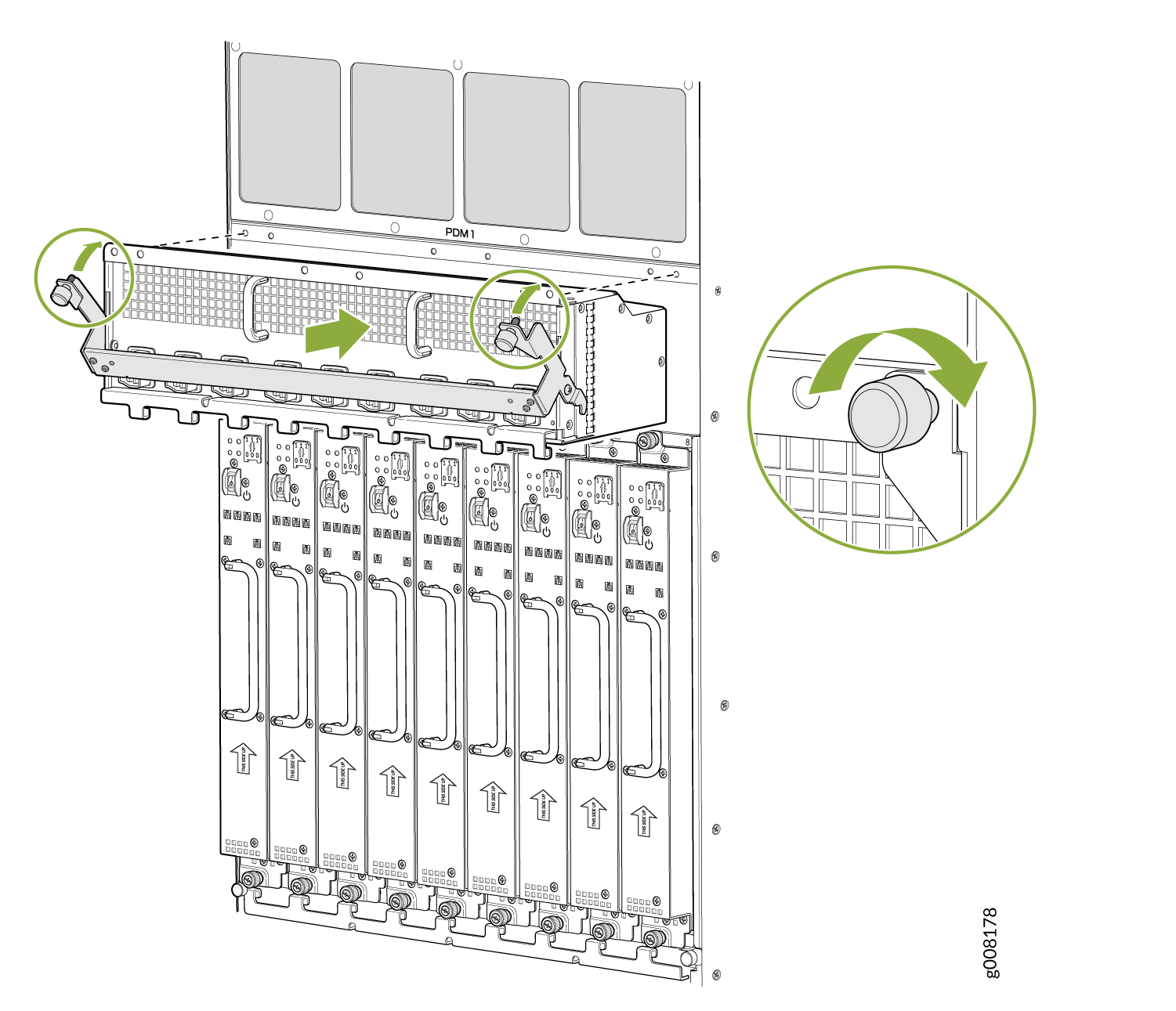
For the DC-powered router, make sure the switch is set to 60 A, or 80 A to match the DC circuit input feed. This does not apply to the 240 V China DC PDM or the universal (HVAC/HVDC) PDM.

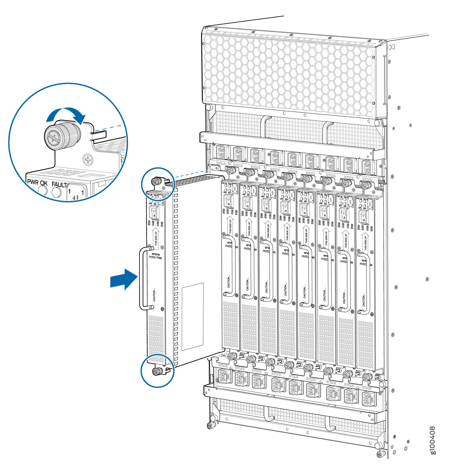
Reinstalling the Power Supply Modules

To reinstall the AC, DC, or universal (HVAC/HVDC) PSMs, follow this procedure for each PSM (see Figure 5, Figure 6, Figure 7, and Figure 8).

  1. Remove the PSM to be installed out of the ESD bag, and identify the slot where it will be installed; 0 through 8.
    Note:

    The MX2000 PSMs can be installed in any order in the chassis.

  2. For an AC-powered router, move the AC power switch on the PSMs to the off (O) position. For a DC-powered router, move the DC power switch on the PSMs to the off (O) position.
  3. While holding the handle, using both hands, slide the PSM straight in until the PSM is fully seated into the chassis slot.
  4. The PSM faceplate should be flush with adjacent PSMs.
Figure 5: Reinstalling an AC Power Supply ModuleReinstalling an AC Power Supply Module
Figure 6: Reinstalling a DC Power Supply Module (-48 V)Reinstalling a DC Power Supply Module (-48 V)
Figure 7: Reinstalling a DC Power Supply Module (240 V China)Reinstalling a DC Power Supply Module (240 V China)
Figure 8: Reinstalling a High-Voltage Universal (HVAC/HVDC) Power Supply ModuleReinstalling a High-Voltage Universal (HVAC/HVDC) Power Supply Module

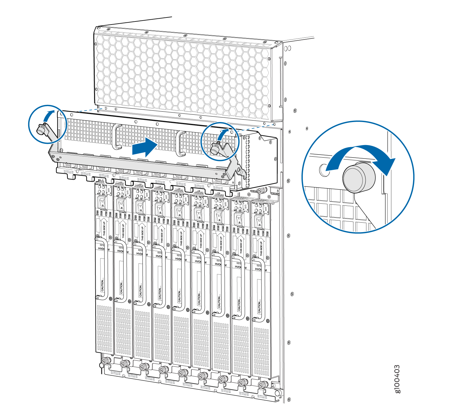
Reinstalling the Fan Trays

To reinstall the upper or lower fan trays, (see Figure 9 and Figure 10):

  1. Loosen the two captive screws on each side of the fan tray access panel, and open the panel.
  2. Take each fan tray to be installed out of its electrostatic bag, and identify the slot on the fan tray where it will be connected.
  3. While grasping the handle, place one hand under the fan tray for support, and align it into the slot.
  4. Press and hold the latch while guiding the fan tray half way in until it stops.
    Note:

    The fan tray has a safety mechanism so that the fan tray cannot be removed in one motion.

  5. Press and hold the latch a second time while inserting the fan tray completely into the router.
  6. Tighten the two captive screws on the fan tray faceplate.
  7. Close the fan tray access panel, and tighten the captive screws to secure it in place.
Figure 9: Reinstalling Upper Fan TraysReinstalling Upper Fan Trays
Figure 10: Reinstalling Lower Fan TraysReinstalling Lower Fan Trays

Reinstalling the SFBs

To reinstall an SFB (see Figure 11):

CAUTION:

Before removing or replacing an SFB, ensure that the ejector handles are stored horizontally and pressed toward the center of the SFB.

  1. Attach an electrostatic discharge (ESD) grounding strap to your bare wrist, and connect the strap to one of the ESD points on the chassis.
  2. Take each SFB to be installed out of its electrostatic bag, and identify the slot on the SFB where it will be connected.
  3. Carefully align the sides of the SFB with the guides inside the chassis.
  4. Slide the SFB into the chassis until you feel resistance, carefully ensuring that it is correctly aligned.
  5. Grasp both ejector handles, and gently close them inward simultaneously until the SFB is fully seated.
  6. Place the ejector handles in their proper position, vertically, and toward the center of the board.
    CAUTION:

    If one of the SFBs fails, do not remove the failed SFB until you have a replacement or blank panel to install.

Figure 11: Reinstalling an SFBReinstalling an SFB

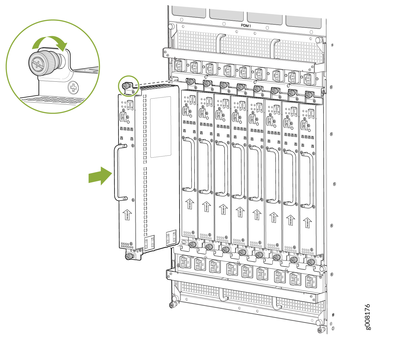
Reinstalling the Adapter Card

To reinstall an adapter card (see Figure 12):

  1. Attach an electrostatic discharge (ESD) grounding strap to your bare wrist, and connect the strap to one of the ESD points on the chassis.
  2. Take each adapter card to be installed out of its electrostatic bag, and identify the slot where it will be installed.
  3. Locate the slot in the card cage in which you plan to install the adapter card.
  4. Ensure that the adapter card is right-side up, with the text on the faceplate facing upward.
  5. Lift the adapter card into place, and carefully align first the bottom, and then the top of the adapter card with the guides inside the card cage.
  6. Slide the adapter card all the way into the card cage until you feel resistance.
  7. Grasp both ejector handles, and gently close them inward simultaneously until the adapter card is fully seated.
Figure 12: Reinstalling an Adapter CardReinstalling an Adapter Card

Reinstalling the MPCs

To reinstall an MPC (see Figure 13):

  1. Attach an electrostatic discharge (ESD) grounding strap to your bare wrist, and connect the strap to one of the ESD points on the chassis.
  2. Take each MPC to be installed out of its electrostatic bag, and identify the slot where it will be connected.
  3. Verify that each fiber-optic MPC has a rubber safety cap covering the transceiver. If it does not, cover the transceiver with a safety cap.
  4. Locate the slot in the adapter card in which you plan to install the MPC.
  5. Ensure that the MPC is right-side up, with the text on the faceplate facing upward.
  6. Lift the MPC into place, and carefully align first the bottom, and then the top of the MPC with the guides inside the adapter card.
  7. Slide the MPC all the way into the adapter card until you feel resistance.
  8. Turn both knobs and rotate them simultaneously clockwise until the MPC is fully seated into the adapter card.
Figure 13: Reinstalling an MPC Reinstalling an MPC

Reinstalling the CB-REs

To reinstall a CB-RE (see Figure 14):

  1. Attach an electrostatic discharge (ESD) grounding strap to your bare wrist, and connect the strap to one of the ESD points on the chassis.
  2. Take each CB-RE to be installed out of its electrostatic bag, and identify the slot on the CB-RE where it will be connected.
  3. Verify that each fiber-optic CB-RE has a rubber safety cap covering the transceiver. If it does not, cover the transceiver with a safety cap.
  4. Locate the slot in the CB-RE card cage in which you plan to install the CB-RE.
  5. Ensure that the CB-RE is right-side up, with the text on the faceplate of the CB-RE facing upward.
  6. Lift the CB-RE into place, and carefully align first the bottom, then the top of the CB-RE with the guides inside the card cage.
  7. Slide the CB-RE all the way into the card cage until you feel resistance.
  8. Grasp both ejector handles, and gently close them inward simultaneously until the CB-RE is fully seated.
Figure 14: Reinstalling a CB-REReinstalling a CB-RE