ON THIS PAGE
Installing MX2000 Router DC Power Supply Modules (240 V China)
Connecting an MX2008 DC Power Distribution Module (-48 V) Cable
Connecting Power to a DC-Powered MX2008 Router with Power Distribution Modules (-48 V)
Connecting Power to a DC-Powered MX2000 Router with DC Power Distribution Modules (240 V China)
Connecting an MX2000 DC Router Power Distribution Module (240 V China) Cable
Connecting the MX2008 to DC Power
Installing MX2008 DC Power Supply Modules (-48 V)
To install an MX2008 DC PSM:
- On the PSM, slide the plastic cover away from the input
mode switch to expose the dual DIP switches. Move the input mode DIP
switch 0 (left switch) to the ON position for the bottom feed INP0 (expected
to be connected), and DIP switch 1 (right switch)
to the ON position for the top feed INP1 (expected to be connected). If both DIP switches 0 and 1 are turned to the ON position, then both top and bottom feeds are expected
to be connected (see Figure 1). Note:
The DIP switches are used only to indicate presence of a feed. If both feeds are present, power is always drawn from feed 0. Power will be drawn from feed 1 only if feed 0 fails. A PSM failure triggers the alarm LED on the craft interface.
Figure 1: Selecting DC Power System Feed Redundancy
- Using both hands, grasp the handle and slide the PSM straight
into the chassis until the PSM is fully seated in the chassis slot.
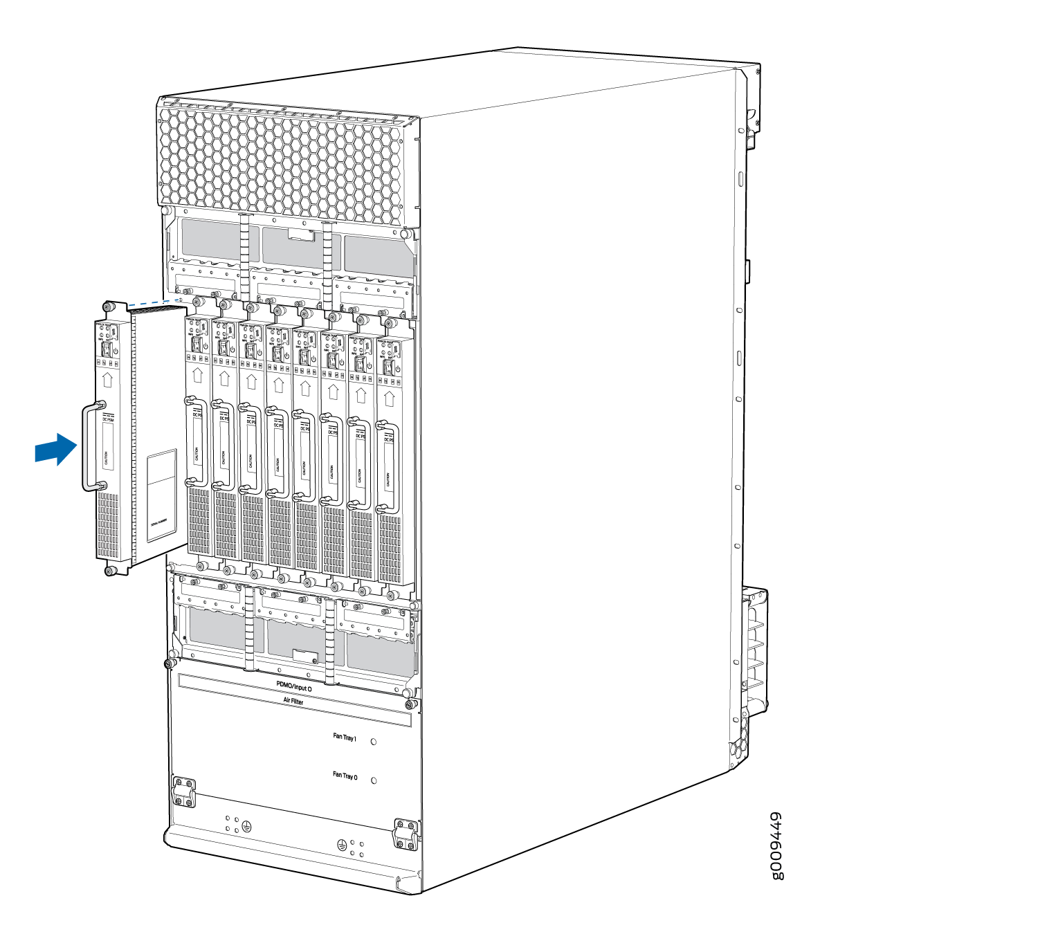
Tighten the two captive screws (see Figure 2).Figure 2: MX2008 Router with DC Power Supply Modules Installed
- Repeat Steps 1 through 7 for installing
PSMs in slots 0, 1, and 2, where required.Figure 3: MX2008 DC Power Supply Module Front View
 Note:
Note:Each PSM slot not occupied by a DC PSM must be covered by a PSM blank panel.
See Also
Installing MX2000 Router DC Power Supply Modules (240 V China)
To install an MX2000 DC PSM (240 V China):
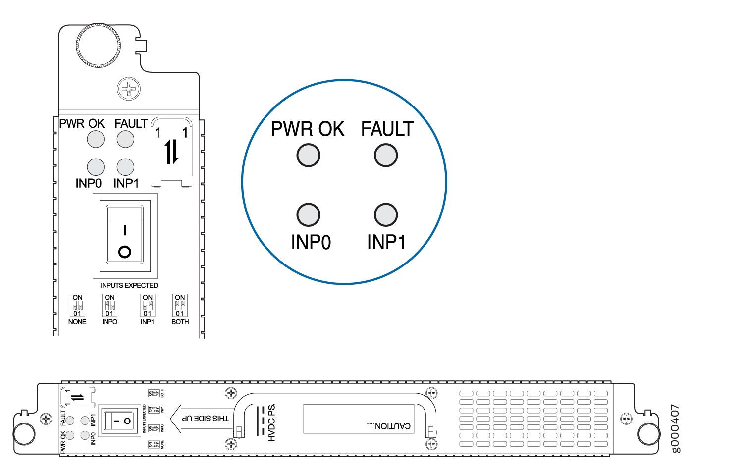
- On the PSM, slide the plastic cover away from the input
mode switch to expose the dual DIP switches. Move the input mode DIP
switch 0 (left switch) to the ON position for the bottom feed INP0 (expected
to be connected), and DIP switch 1 (right switch)
to the ON position for the top feed INP1 (expected to be connected). If both DIP switches 0 and 1 are turned to the ON position, then both top and bottom feeds are expected
to be connected, (see Figure 4).
In addition, a PSM failure triggers the alarm LED on the craft interface.
Note:The DIP switches are only used to indicate presence of a feed. If both feeds are present, power is always drawn from feed 0. Power will be drawn from feed 1 only if feed 0 fails.
Figure 4: Selecting DC Power (240 V China) Subsystem Feed Redundancy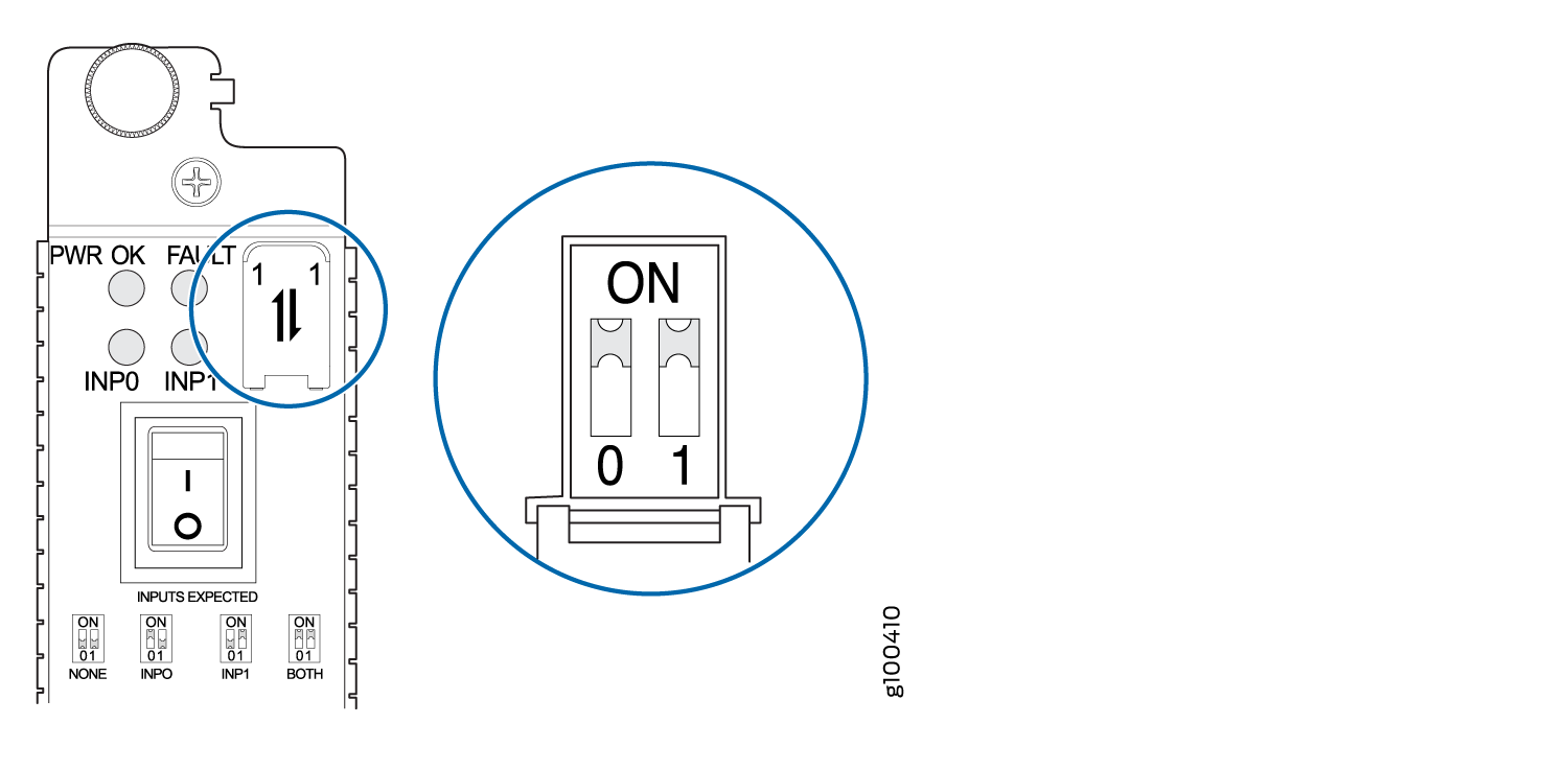
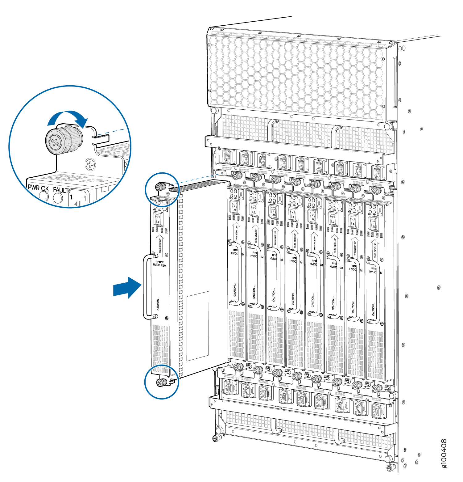
- Using both hands, grasp the handle and slide the PSM straight
into the chassis until the PSM is fully seated in the chassis slot.
Tighten the two captive screws (see Figure 5). Apply
between 10 lb-in. (1.13 Nm) to 12 lb-in. (1.35 Nm)
of torque to each screw. Do not overtighten the screws. Figure 5: Installing an MX2020, MX2010, MX2008 Router DC Power Supply Module (240 V China)
- Repeat Steps Installing MX2008 DC Power Supply Modules (-48 V) through 7 for
installing PSMs in slots 0, 1, and 2, where required.Figure 6: MX2000 DC Power Supply Module Front View (240 V China)
 Note:
Note:Each PSM slot not occupied by a (240 V China) DC PSM must be covered by a PSM blank panel.
Connecting an MX2008 DC Power Distribution Module (-48 V) Cable
Before performing DC power procedures, disconnect all power sources. To ensure that all power is off, locate the circuit breaker on the panel board that services the DC circuit, switch the circuit breaker to the OFF position, and tape the switch handle of the circuit breaker in the OFF position.
To connect a power cable for a DC PDM:
- Secure the power cable lug to the terminal studs, first
with the flat washer, then with the split washer, and finally with
the nut. Apply between 23 lb-in. (2.6 Nm) and 25 lb-in.
(2.8 Nm) of torque to each nut (see Figure 7). Do not overtighten
the nut. (Use a 7/16-in. [11 mm)] torque-controlled driver
or socket wrench.)CAUTION:
Ensure that each power cable lug seats flush against the surface of the terminal block as you are tightening the nuts. Ensure that each nut is properly threaded onto the terminal stud. The nut should be able to spin freely with your fingers when it is first placed onto the terminal stud. Applying installation torque to the nut when the nut is improperly threaded might result in damage to the terminal stud.
CAUTION:The maximum torque rating of the terminal studs on the DC PDM is 25 lb-in. (33.89 Nm). The terminal studs might be damaged if excessive torque is applied. Use only a torque-controlled driver or socket wrench to tighten nuts on the DC PDM terminal studs.
Figure 7: Connecting Power Cables to the DC Power Distribution Module
See Also
Connecting Power to a DC-Powered MX2008 Router with Power Distribution Modules (-48 V)
Before performing DC power procedures, ensure that power is removed from the DC circuit. To ensure that all power is off, locate the circuit breaker on the panel board that services the DC circuit, switch the circuit breaker to the OFF position, and tape the switch handle of the circuit breaker in the OFF position.
You connect DC power to the router by attaching power cables from the external DC power sources to the terminal studs on the PDM faceplates. You must provide the power cables (the cable lugs are not supplied with the router).
To connect the DC source power cables to the router:
-
Install heat-shrink tubing insulation around the power cables at the connection
point of the DC power supply
terminal.
To install heat-shrink tubing:
-
Slide the tubing over the portion of the cable where it is attached to the lug barrel. Ensure that tubing covers the end of the wire and the barrel of the lug attached to it.
-
Shrink the tubing with a heat gun. Ensure that you heat all sides of the tubing evenly so that it shrinks around the cable tightly.
Figure 8 is a representational diagram that shows the steps to install heat-shrink tubing.
Note:Do not overheat the tubing.
Figure 8: How to Install Heat-Shrink Tubing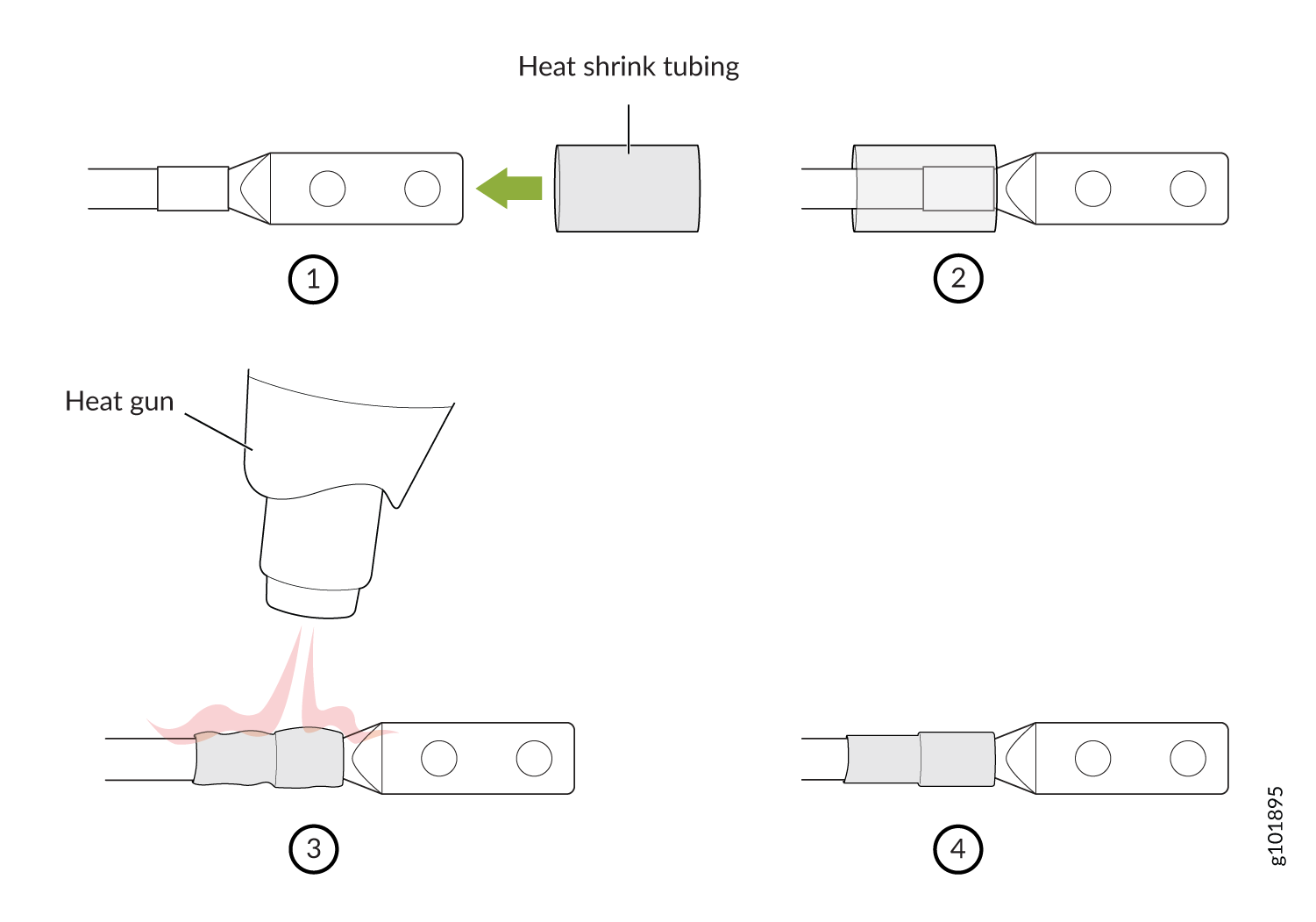
-
The MX2008 router has more than one connection to power after it is fully connected. Disconnect all power sources before servicing the PSMs or PDMs to avoid electrical shock.
See Also
Connecting Power to a DC-Powered MX2000 Router with DC Power Distribution Modules (240 V China)
Before performing DC power procedures, ensure that power is removed from the DC circuit. To ensure that all power is OFF, locate the circuit breaker on the panel board that services the DC circuit, switch the circuit breaker to the OFF position, and tape the switch handle of the circuit breaker in the OFF position.
You connect DC (240 V China) power to the router by attaching power cables from the external DC power sources to the DC power cable that is connected to the PDM. The power cables are orderable (CBL-PWR-240V-CH).
To connect the DC (240 V China) source power cables (CBL-PWR-240V-CH) to the router:
- Plug the power cord into the power sockets
on the DC PDM (240 V China). Refer to Figure 1. Apply slight pressure
so that the power cord is firmly seated in the power socket until
you feel it engage. As you plug in each power cord, the power LED
for the socket lights up green.Figure 10: Connecting Power
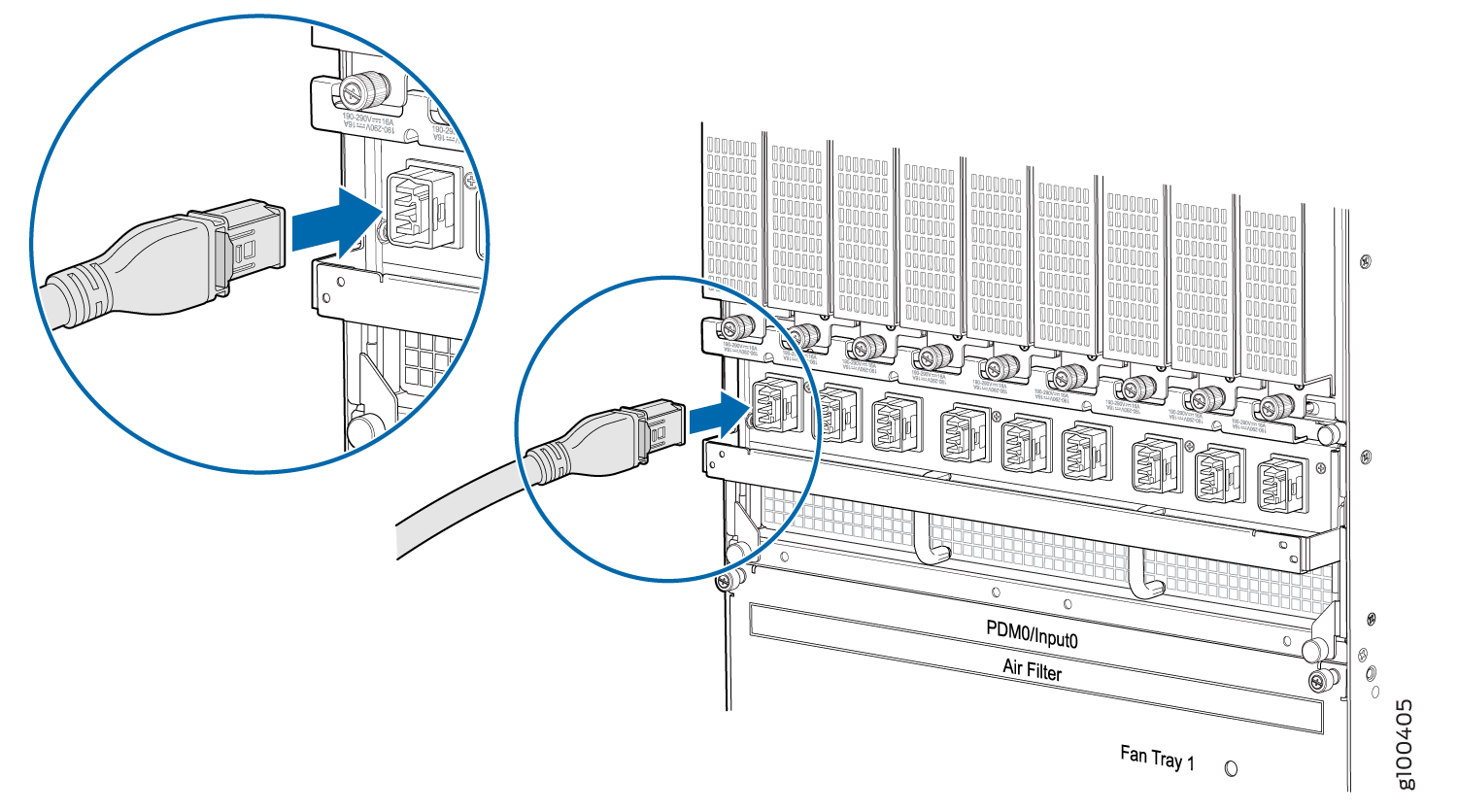
Connecting an MX2000 DC Router Power Distribution Module (240 V China) Cable
Before performing DC power procedures, disconnect all power sources. To ensure that all power is OFF, locate the circuit breaker on the panel board that services the DC circuit, switch the circuit breaker to the OFF position, and tape the switch handle of the circuit breaker in the OFF position.
To connect the DC (240 V China) source power cables (CBL-PWR-240V-CH) to the router:
- Plug the power cord into the power sockets
on the DC PDM (240 V China). Refer to Figure 1. Press the latch on
the side of the power cable before pushing it in. Apply slight pressure
so that the power cord is firmly seated in the power socket until
you feel it engage. As you plug in each power cord, the power LED
for the socket lights up green.Figure 11: Connecting PowerFigure 12: Unplugging the 240 V China Power Cord an MX2000 Router
- Connect the power cable (CBL-PWR-240V-CH) to the DC power
source. See Figure 13.Figure 13: 240 V China Power Cable
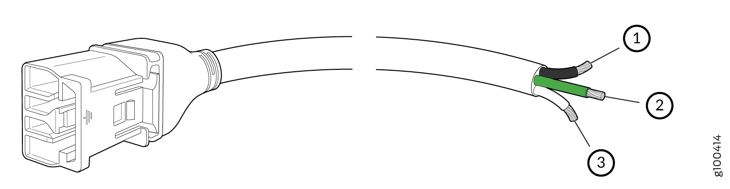 1—
1—Negative
3—Positive
2—Ground
Powering On the DC-Powered (-48 V) MX2008 Router
To power on a DC-powered MX2008 router:
See Also
Powering On the DC-Powered (240 V China) MX2000 Router
To power on a DC-powered router: