EX9200 Host Subsystem
Host Subsystem in an EX9200 Switch
Switching and routing functionality, system management, and system control functions of an EX9200 switch are performed by host subsystem. A host subsystem consists of a Routing Engine functioning together with a Switch Fabric.
You can install either one or two host subsystems in the front panel of an EX9204 or an EX9208 switch. A base configuration EX9204 and EX9208 switch has one host subsystem. A redundant configuration EX9204 and EX9208 switch has a second host subsystem.
You can install either two or three host subsystems in the front panel of an EX9214 switch. A base configuration EX9214 switch has two host subsystems. A redundant configuration EX9214 switch has a third host subsystem.
In EX9204 and EX9208 switches, we recommend that you install two host subsystems for redundant protection. If you install only one host subsystem, we recommend that you install it in slot 0. In EX9214 switches, we recommend that you install three host subsystems for redundant protection. If you install only two host subsystems, we recommend that you install it in slot 0 and 1.
Each host subsystem has LEDs in the craft interface that display its status. See Craft Interface in an EX9200 Switch.
See Also
Routing Engine Module in an EX9200 Switch
The Routing Engine module (RE module) is an Intel-based platform that runs Juniper Networks Junos operating system (Junos OS). Software processes that run on the RE module maintain the routing tables, manage the routing protocols used on the switch, control the router interfaces and some of the chassis components, and provide the interface for system management and user access to the switch.
In an EX9204, EX9208, or EX9214 switch, you can install one or two RE modules in the Switch Fabric modules (SF modules) that are installed in slots on the front panel of the switch. If you install two RE modules, one functions as the primary and the other functions as the backup. If the primary RE module fails or is removed and the backup is configured appropriately, the backup takes over as the primary. The backup RE module is hot-insertable and hot-removable, whereas the primary RE module is only hot-insertable. See Figure 1 and Figure 2. A USB port on the RE module accepts a USB memory card that loads the Junos OS.
In EX9214 switches, you must install an RE module only in the SF modules installed in slots 7 and 8 labeled 0 and 1.
If you have installed only one RE module, you must power off the switch before removing the RE module.
A base-configuration EX9204, EX9208, or EX9214 switch has only one RE module. See EX9204 Switch Configurations, EX9208 Switch Configurations, and EX9214 Switch Configurations. You can add a second RE module to the configuration for redundancy.
We recommend that you install two RE modules in EX9204, EX9208, and EX9214 switches for redundancy.
The RE module performs the following functions:
Provides switching functionality to the switch through the switching plane
Powers the line cards on and off
Controls system resets and the boot sequence for the switch
Monitors and controls the fan speed, power status for various chassis components, and craft interface LEDs
The switch ships with the RE modules preinstalled. There are two copies of the software:
One copy on the solid-state drive (SSD) in the RE module.
One copy on a USB flash drive that can be inserted into the slot on the RE module faceplate.
The RE module boots from the storage media in the following order: the USB device (if present), then the SSD, and finally the LAN.
Starting with Junos OS Release 17.1R1, EX9200 switches support the EX9200-RE2 module. The EX9200-RE2 module supports virtual machine (VM) architecture in an EX9200 switch. Only the EX9200-SF2 module supports the EX9200-RE2 module. Starting with Junos OS Release 17.1R1, you cannot form a Virtual Chassis using an EX9200 switch.
The EX9200-RE module and the EX9200-RE2 module are not interoperable. Do not install both the RE modules in the same switch chassis.
Starting with Junos OS Release 16.1, you can use EX9200 switches as an aggregation device in Junos Fusion Enterprise. Starting with Junos OS Release 17.4, you can use EX9200 switches with EX9200-RE2 module installed in it as an aggregation device in Junos Fusion Enterprise. See Understanding Junos Fusion Enterprise Software and Hardware Requirements for the list of line cards that support this configuration.
Figure 1 shows the EX9200-RE module in an EX9200 switch.
Each EX9200-RE module consists of the following components:
Extractor clips—Control the locking system to securely install and remove the EX9200-RE module.
AUX port—Connects the EX9200-RE module to a modem or other auxiliary device.
CONSOLE port—Connects the EX9200-RE module to a system console through a cable with an RJ-45 connector. See Connecting an EX9200 Switch to a Management Console or an Auxiliary Device.
ETHERNET port—Connects the EX9200-RE module through an Ethernet connection to a management LAN (or any other device that plugs into an Ethernet connection) for out-of-band management. See Connecting an EX9200 Switch to a Network for Out-of-Band Management.
USB port—Hosts a removable media interface through which you can install the Junos OS manually. See USB Port Specifications for an EX Series Switch.
SATA SSD 1 and SATA SSD 2 slots—Host primary storage for software images, configuration files, and microcode. Also provide secondary storage for log files and memory dump files.
RESET button—Reboots the EX9200-RE module when pressed.
ONLINE/OFFLINE button—Turns the EX9200-RE module online or offline when pressed.
Status LEDs—Indicate the status of the EX9200-RE module. Each EX9200-RE module has four LEDs labeled MASTER, STORAGE, ONLINE, and OK/FAIL on the faceplate.
Captive screws—Secure the EX9200-RE module in place.
Figure 2 shows the EX9200-RE2 module in an EX9200 switch.
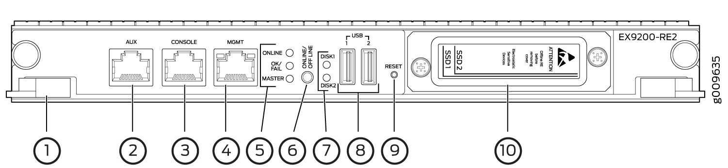
1 — Extractor clips | 6 — ONLINE/OFFLINE button |
2 — Auxiliary port (AUX) | 7 — SSD LEDs—DISK1 and DISK2 |
3 — Console port (CONSOLE) | 8 — USB ports—USB1 and USB2 |
4 — Management port (MGMT) | 9 — RESET button |
5 — LEDs—ONLINE, OK/FAIL, and MASTER | 10 — SSD slots—SSD 1 and SSD 2 |
Each EX9200-RE2 module consists of the following components:
Extractor clips—Control the locking system to securely install and remove the EX9200-RE2 module.
AUX port—Connects the EX9200-RE2 module to a modem or other auxiliary device.
CONSOLE port—Connects the EX9200-RE2 module to a system console through a cable with an RJ-45 connector. See Connecting an EX9200 Switch to a Management Console or an Auxiliary Device.
MGMT port—Connects the EX9200-RE2 module through an Ethernet connection to a management LAN (or any other device that plugs into an Ethernet connection) for out-of-band management. See Connecting an EX9200 Switch to a Network for Out-of-Band Management.
Status LEDs—Indicate the status of the EX9200-RE2 module. Each EX9200-RE2 module has five LEDs labeled MASTER, ONLINE, OK/FAIL, DISK1, and DISK2 on the faceplate.
ONLINE/OFFLINE button—Turns the EX9200-RE2 module online or offline when pressed.
USB1 and USB2 ports—Host a removable media interface using which you can install the Junos OS manually. See USB Port Specifications for an EX Series Switch.
SSD 1 and SSD 2 slots—Host primary storage for software images, configuration files, and microcode. Also provide secondary storage for log files and memory dump files.
RESET button—Reboots the EX9200-RE2 module when pressed.
Captive screws—Secure the EX9200-RE2 module in place.
For the specifications of the Routing Engine modules, see Table 1.
RE Module |
Processor |
Memory |
Connection to Packet Forwarding Engines |
Disk |
Media |
First Junos OS Release |
|---|---|---|---|---|---|---|
EX9200-RE |
RE-S-EX9200-1800X4 (4 cores, 1.73 GHz) |
16 GB |
Gigabit Ethernet |
32- GB hard disk |
4- GB CompactFlash card |
12.3R2 |
EX9200-RE2 |
RE-S-EX9200-2X00x6 (6 cores, 2 GHz) |
64 GB |
Gigabit Ethernet |
50- GB SSD X 2 |
No flash memory |
17.1R1 |
Routing Engine Module LEDs in an EX9200 Switch
Each Routing Engine module (RE module) has LEDs on the module faceplate. Table 2 describes the functions of these LEDs on the EX9200-RE and Table 3 describes the functions of these LEDs on the EX9200-RE2.
LED Label |
Status |
State and Description |
|---|---|---|
MASTER |
Blue |
RE module is functioning as the primary. |
Unlit |
RE module is either functioning as the backup or not installed. |
|
STORAGE |
Green |
Blinking—Indicates activity on the SSD. |
ONLINE |
Green |
|
OK/FAIL |
Red |
RE module has failed. |
LED Label |
Status |
State and Description |
|---|---|---|
MASTER |
Blue |
RE module is functioning as the primary. |
Unlit |
RE module is either functioning as the backup or not installed. |
|
ONLINE |
Unlit |
The RE is powered off |
Green |
When the RE module is powering on:
When the RE module is powering off:
|
|
OK/FAIL |
Red |
RE module has failed. |
DISK1 |
Green |
Blinking—Indicates activity on the SSD. |
DISK2 |
Green |
Blinking—Indicates activity on the SSD. |
See Also
Switch Fabric Module in an EX9200 Switch
The Switch Fabric serves as the central nonblocking matrix through which all network data passes.
Switch Fabric modules (SF modules) are installed horizontally on the front panel of the switch chassis. You can install either one or two SF modules in an EX9204 or EX9208 switch and two or three SF modules in an EX9214 switch. A base-configuration EX9204 or EX9208 switch has only one SF module, and a base-configuration EX9214 switch has two SF modules. See EX9204 Switch Configurations, EX9208 Switch Configurations, or EX9214 Switch Configurations.
In EX9204 and EX9208 switches, you can add a second SF module to the configuration for host subsystem redundancy. In EX9214 switches, you can add a third SF module to the configuration for host subsystem redundancy. If two SF modules are installed, one SF module functions as the primary and the other functions as the backup. If the primary SF module or its components fails or is removed, the backup module takes the role of primary.
The Routing Engine module (RE module) installs directly into a slot on the SF module. The Switch Fabric contains logic that determines which Routing Engine is the primary. The primary Routing Engine controls many internal functions of the SF module.
The backup SF module is hot-insertable and hot-removable, but the primary SF module is only hot-insertable.
The key functions of the Switch Fabric are:
-
Monitor and control system functions
-
Interconnection of all line cards
-
Clocking, system resets, and booting control
-
Routing Engine carrier
Figure 3 shows the original SF module, EX9200-SF.
Starting with Junos OS Release 14.1, a high-speed SF module, EX9200-SF2, is available. Compared to the original SF module, EX9200-SF, the EX9200-SF2 offers increased bandwidth, providing higher-capacity traffic support in settings that require greater interface density (slot and capacity scale).
The EX9200-SF2 supports all EX9200 line cards.
Figure 4 shows the high-speed SF module, EX9200-SF2.
The SF modules install horizontally into the front of the chassis. If any slots are empty, you must install a cover panel.
The SF module has the following components:
-
Chassis management Ethernet switch
-
I2C bus logic, used for low-level communication with each component
-
Component redundancy circuitry
-
Control Board/Routing Engine primary-role mechanism
-
Gigabit Ethernet switch that is connected to the embedded CPU complex on all components
-
Control field-programmable gate array (FPGA)—Provides the Peripheral Component Interconnect (PCI) interface to the Routing Engine
-
1000Base-T Ethernet controller—Provides a 1-Gbps Ethernet link between the Routing Engines
-
Ethernet switch—Provides 1-Gbps link speeds between the Routing Engine and the line cards
-
External clock interface—Allows BITS or GPS clock source input to the centralized timing circuit, or allows centralized timing to be output to BITS or GPS
-
Circuits for chassis management and control
-
Power circuits for the Routing Engine and the Switch Fabric
-
SF module LEDs—Indicate system status. (See Switch Fabric Module LEDs in an EX9200 Switch).
-
Ejector levers—Used for installing and removing the SF module
-
Captive screws—Secure the SF module in place
See Also
Switch Fabric Module LEDs in an EX9200 Switch
The Switch Fabric module (SF module) has three LEDs on the module faceplate. Table 4 describes the functions of these LEDs. For information about the LEDs on the EX9200-SF3, see Table 4.
LED |
Status |
Description |
|---|---|---|
FABRIC ACTIVE |
Green |
Switch Fabric is in active mode. |
Unlit |
Switch Fabric is offline. |
|
FABRIC ONLY |
Green |
On steadily—Switch Fabric is operating in fabric-only mode. |
Unlit |
Switch Fabric is not operating in fabric-only mode. |
|
OK/FAIL |
Green |
Switch Fabric is online. |
Red |
Switch Fabric has failed. |
|
Unlit |
Switch Fabric is offline. |
The BITS, GPS, and UTI LEDs, located next to the EXT CLK port, indicate the status of the respective clocking interface. These LEDs are not supported.
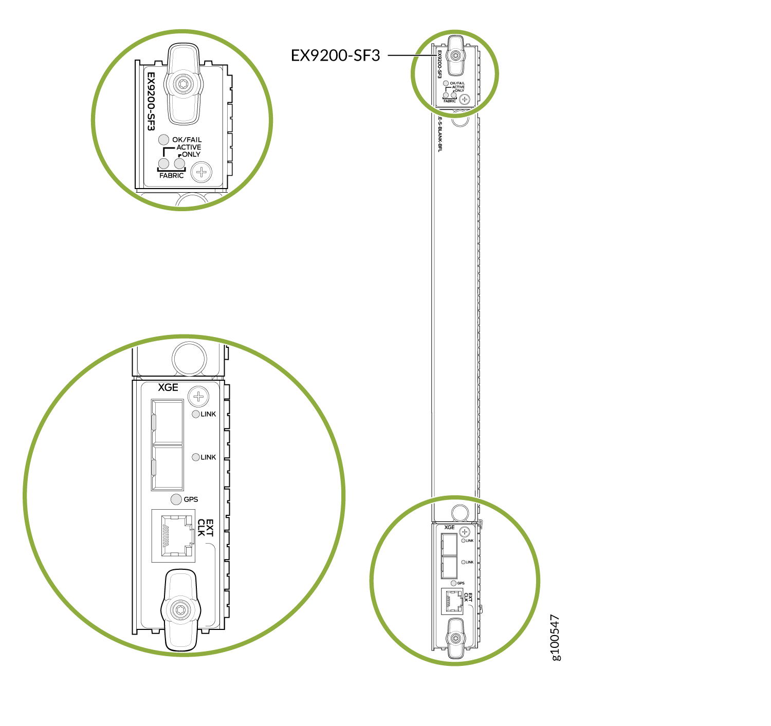
EX9200-SF3 Module in an EX9200 Switch
Starting in Junos OS Release 20.3R1, the EX9200-SF3 Switch Fabric module is available. The EX9200-SF3 provides improved fabric performance and bandwidth capabilities for high-capacity line cards. In a redundant configuration, the EX9200-SF3 provides fabric bandwidth of up to 1 Tbps per slot. In a nonredundant configuration the EX9200-SF3 provides fabric bandwidth of up to 1 Tbps per slot (four fabric planes) and 1.5 Tbps per slot fabric bandwidth when all six fabric planes are used (with EX9200-15C line cards).
Figure 5 shows the SF module, EX9200-SF3.
The EX9200-SF3
Software release |
Junos OS Release 20.3R1 and later Name in CLI: |
- EX9200-SF3 Components and Features
- EX9200-SF3 LEDs
- EX9200-SF3 Fabric Bandwidth Performance and Redundancy
- EX9200-SF3 Maximum Power Consumption per Ambient Temperature and CB Slot
- Interoperability with Existing Hardware
- EX9200-SF3 Unsupported Functions and Capabilities from Legacy Switch Fabric Modules
EX9200-SF3 Components and Features
Component/Feature |
Description |
|---|---|
XGE ports |
Two Ethernet ports provide 10GbE and 1GbE SFP+ interfaces. These ports also are connected to the Ethernet control switch, which limits the traffic for the 10GbE port and provides security to prevent unwanted access to the control plane through the external ports. |
GPS port |
One RJ-45 GPS external clock interface port receives GPS and PPS timing from the GPS external interface. A red LED indicates there is no clock present or the clock is not OK. A green LED indicates the clock interface is active and OK. If the LED is off, the clock interface is not enabled. |
External clock interface |
The external clock interface is on the EX9200-SF3 front panel. The clock source interface receives GPS and PPS timing from the GPS external interface. |
Centralized Stratum3E clock module |
The clock module performs clock monitoring, filtering, and holdover on the centralized fabric card. This centralized clocking architecture also provides clock cleanup and distribution. |
In-system removable Routing Engine |
The in-system Routing Engine can support any new Routing Engine that conforms to the standard modular Routing Engine I/O interface and form factor. Note:
When a Routing Engine is not installed in the EX9200-SF3, you need to cover the empty slot with a blank panel. |
Hot-swappable |
The EX9200-SF3 and associated Routing Engine assembly are hot-swappable. The system software provides a mechanism to shut down the Routing Engine/EX9200-SF3. The system software also provides a method to reset or reboot the Routing Engine/EX9200-SF3. This support is provided through CLI commands and various hardware support circuits. Note:
Before removing the module, you must bring the Routing Engine offline to avoid corrupting the hard drive. |
System upgrade capabilities |
See Upgrading to an EX9200-SF3 for details. |
Redundancy |
With three EX9200-SF3 Switch Fabric modules installed, the EX9214 provides 2 + 1 redundancy. With two EX9200-SF3s installed, the EX9204 and EX9208 provide 1 + 1 redundancy. |
DMR |
Supports dynamic multicast replication (DMR). |
GRES |
Supports graceful Routing Engine switchover (GRES). |
Hitless operation |
Allows you to upgrade programmable parts and reboot with “hitless” operation if the redundant EX9200-SF3s are inserted in the system and are operational. |
Removable Routing Engine module |
You can remove the Routing Engine module FRU in the existing form factor. |
EX9200-SF3 LEDs
Table 5 describes the functions of the EX9200-SF3 LEDs.
LED |
Status |
Description |
|---|---|---|
OK/FAIL |
Green |
Switch Fabric is online. |
Red |
Switch Fabric has failed. |
|
Unlit |
Switch Fabric is offline. |
|
FABRIC ACTIVE |
Green |
Switch Fabric is in active mode. |
Unlit |
Switch Fabric is offline. |
|
FABRIC ONLY |
Green |
On steadily—Switch Fabric is operating in fabric-only mode. |
Unlit |
Switch Fabric is not operating in fabric-only mode. |
|
XGE Port LINK |
Green |
Port is enabled and a link is established. |
Unlit |
Port is disabled or no link is established. |
|
GPS EXT CLK |
Green |
A link is established. |
Amber (blinking) |
There is activity on the clocking interface. |
EX9200-SF3 Fabric Bandwidth Performance and Redundancy
EX9214 Switches:
The EX9214 system can contain up to three EX9200-SF3s to provide a total of six switch fabric planes for packet forwarding among the MPCs. Two fabric planes per EX9200-SF3s are required. To achieve full fabric bandwidth performance, three EX9200-SF3s must be installed in the EX9214 chassis.
Two chassis slots are provided in the center of the EX9214 chassis in slots 6 and 7 (also designated as slot SF0 and slot SF1) for two EX9200-SF3s, each equipped with a Routing Engine.
To provide 2 + 1 fabric redundancy for an EX9214, a third EX9200-SF3 must be installed in slot 8 (also designated as slot SF2).
Slot 8 in the EX9214 chassis is a dual-purpose slot, and supports either an EX9200-SF3 or a line card. When the EX9200-SF3/Routing Engine are plugged into slot 8, the Routing Engine is powered down and does not provide any control functionality for the board or the EX9214. The fabric-only LED on the card faceplate will be lit when an EX9200-SF3/Routing Engine assembly is plugged into slot 8.
Once redundancy is configured, the primary EX9200-SF3 controls the chassis.
Graceful upgrades can be achieved on a non-primary redundant EX9200-SF3.
In a redundant configuration, the non-primary redundant Routing Engine can be removed or installed without affecting the switching plane functionality on the EX9200-SF3 in which it resides.
In a nonredundant configuration, all six fabric planes will be in active mode for increased fabric bandwidth.
There is one physical switch fabric per EX9200-SF3 and it acts as two virtual planes in the EX9214.
EX9204 and EX9208 Switches:
You can install either one or two EX9200-SF3s in the EX9204 and EX9208 chassis in the slots labeled 0 and 1.
The EX9200-SF3 in slot 0 (SF0) provides two fabric planes; the EX9200-SF3 in slot 1 (SF1) provides four fabric planes. A total of six fabric planes are available in the EX9204 and EX9208.
In a redundant configuration, two fabric planes on the first EX9200-SF3 and two fabric planes on the other EX9200-SF3 will be in active mode.
There is one physical switch fabric per EX9200-SF3, and it acts as four virtual planes in the EX9204 and EX9208.
Two EX9200-SF3 modules installed in the EX9204 and EX9208 are required for 1 + 1 redundancy. To provide 1 + 1 fabric redundancy, there must be an EX9200-SF3 installed in slot 1.
Note:If SF0 fails, SF1 will be automatically configured with four fabric planes active. In this failover scenario, the EX9200-SF3 will support full line rate 100 percent redundancy.
If SF1 fails, SF0 has only two available fabric planes; therefore, in this failover mode, the line rate will drop to 50 percent.
EX9200-SF3 Maximum Power Consumption per Ambient Temperature and CB Slot
These power consumption values are for the EX9200-SF3 only. They do not include reallocated power.
EX Series Model |
Ambient Temperature |
Maximum Power Consumption |
Slot |
|---|---|---|---|
EX9214 |
131° F (55° C) 104° F (40° C) 77° F (25° C) |
425 W 400 W 385 W |
SF0, SF1, SF2 |
EX9208 |
131° F (55° C) 104° F (40° C) 77° F (25° C) |
295 W 280 W 265 W |
SF0 (primary) |
EX9208 |
131° F (55° C) 104° F (40° C) 77° F (25° C) |
295 W 280 W 265 W |
SF1 (backup) |
EX9204 |
131° F (55° C) 104° F (40° C) 77° F (25° C) |
275 W 260 W 245 W |
SF0 (primary) |
EX9204 |
131° F (55° C) 104° F (40° C) 77° F (25° C) |
295 W 280 W 265 W |
SF1 (backup) |
Interoperability with Existing Hardware
EX9200-SF3 Operating Mode |
EX9204/EX9208/EX9214 |
Supported |
|---|---|---|
|
Enhanced IP/enhanced Ethernet mode only |
EX9200-2C-8XS |
No |
EX9200-4QS |
No |
|
EX9200-6QS |
No |
|
EX9200-MPC |
Yes |
|
EX9200-12QS |
Yes |
|
|
EX9200-15C |
Yes |
|
EX9200-32XS |
Yes |
|
EX9200-40T |
No |
|
EX9200-40F |
No |
|
EX9200-40F-M |
No |
|
EX9200-40XS |
Yes |
|
Supported Routing Engines |
EX9200-RE EX9200-RE2 |
Yes Yes |
Hyper-mode is the default forwarding mode on the EX9200-SF3.
If your deployment does not need hyper-mode, disable hyper-mode using
the set forwarding-options no-hyper-mode CLI command before
installing the Routing Engine into the EX9200-SF3.
Enhanced IP is the default network service on the EX9200-SF3.
EX9200-SF3 Unsupported Functions and Capabilities from Legacy Switch Fabric Modules
The EX9200-SF3 does not support the external UTI/DTI interface (front panel LED and daughter card interface).
The EX9200-SF3 does not interoperate with any previous generation SF modules (EX9200-SF and EX9200-SF2). Smooth upgrade is not supported.
The EX9200-SF3 does not support BITS.
The EX9200-SF3 does not support DPCs.
The EX9200-SF3 does not support mixed mode (DPC + MPC).
The EX9200-SF3 does not support the JAM release.