Connect the EX4100 to Power
Connect Earth Ground to an EX4100 Switch
To ensure proper operation and to meet electromagnetic interference (EMI) requirements, you must connect EX4100 switch models to earth ground before you connect power to the switch. You must use the protective earthing terminal on the switch chassis to connect the switch to earth ground.
You must install the EX4100 switches in a restricted-access location and ensure that the chassis is always properly grounded. EX4100 switches have a two-hole protective grounding terminal on the rear panel of the chassis. Under all circumstances, use this grounding connection to ground the chassis. For AC-powered systems, you must also use the grounding wire in the AC power cord along with the two-hole grounding lug connection. This tested system meets or exceeds all applicable EMC regulatory requirements with the two-hole protective grounding terminal.
Ensure that a licensed electrician has attached the appropriate grounding lug to the grounding cable that you supply. Using a grounding cable with an incorrectly attached lug can damage the switch.
Before you connect earth ground to a EX4100 switch, ensure that you have parts and tools listed in Table 1 available:
| Item | Switch Models | Description |
|---|---|---|
| Earthing terminal location |
All EX4100 switches and EX4100-F switches |
Rear panel of the chassis |
| Grounding cable requirements | All EX4100 switches | 8 AWG (8 mm²), minimum 90° C wire, or
as permitted by the local code—not provided
|
| Grounding lug specifications | All EX4100 switches |
Panduit LCD8-14A-L or equivalent—not provided |
| Screws to secure the grounding lug | All EX4100 switches | Two M5X10mm screws with washer—seperately orderable |
| Tools required | All EX4100 switches |
Number 2 Phillips (+) screwdriver—not provided Electrostatic discharge (ESD) grounding strap—not provided |
To ground the EX4100 switch to a proper ground reference:
-
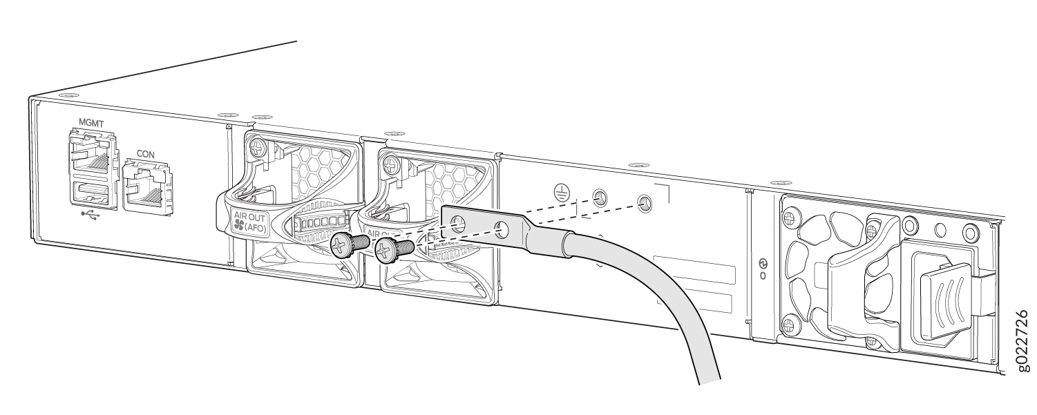
Place the grounding lug attached to the grounding cable over the protective
earthing terminal on the rear panel (see Figure 1).
Figure 1: Connect a Grounding Cable to an EX4100-24P, EX4100-24T, EX4100-48P, EX4100-48T, EX4100-24MP, and EX4100-48MP Switch
Connect AC Power to an EX4100 Switch
Before you connect AC power, ensure that you have the following parts and tools available:
-
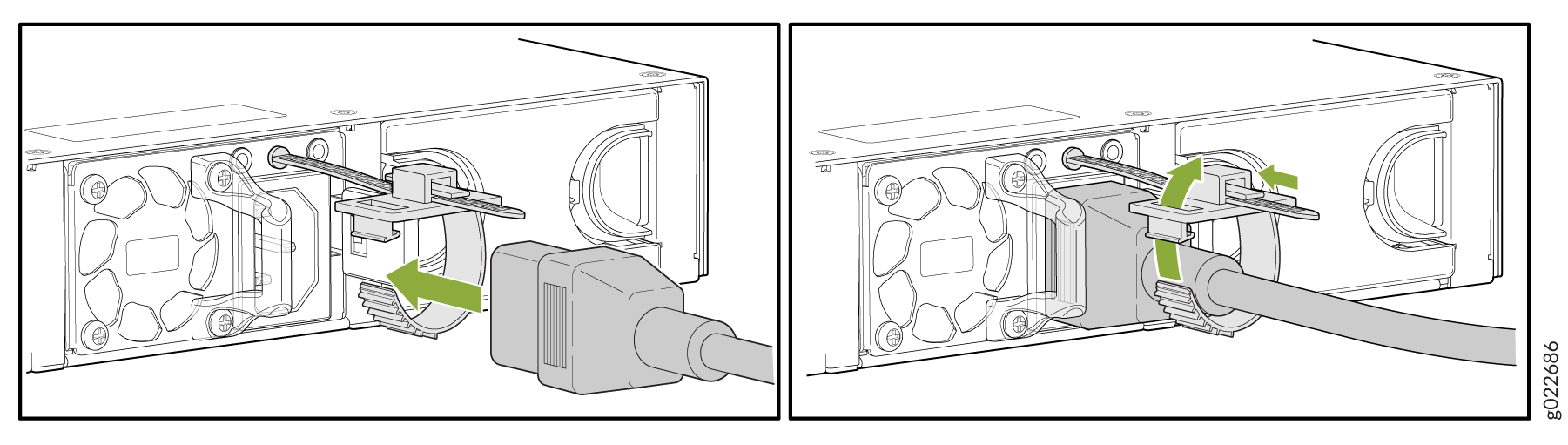
A power cord appropriate for your geographical location
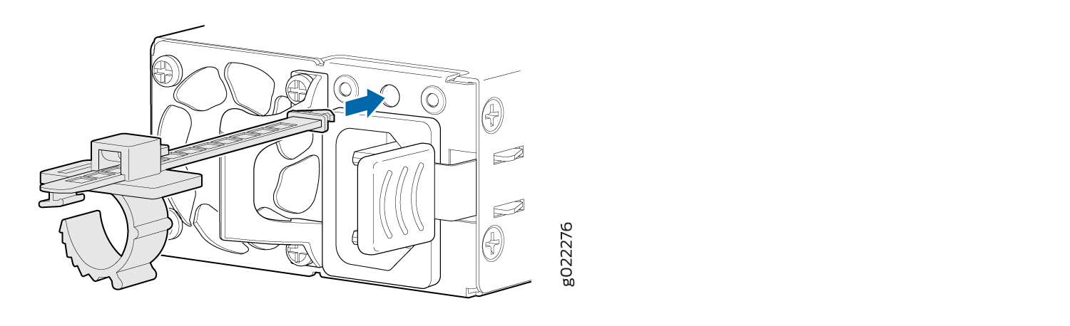
-
A power cord retainer clip (provided with the switch)
Ensure that you have connected the device chassis to earth ground. The AC power cords also provide additional grounding when you connect the power supply in the switch to a grounded AC power outlet by using the AC power cord appropriate for your geographical location (see AC Power Cord Specifications).
For installations that require a separate grounding conductor to the chassis, have a licensed electrician complete this connection before you connect the switch to power. For instructions on connecting earth ground, see Connect Earth Ground to an EX4100 Switch.
You install the power supply in the power supply slot on the rear panel of the switch.
To connect AC power to the switch:
Connect DC Power to an EX4100 Switch
Before you begin connecting DC power to the switch, ensure that you have connected earth ground to the switch chassis.
To meet electromagnetic interference (EMI) requirements and to ensure proper operation, you must connect the switch to earth ground before you connect them to power. For installations that require a separate grounding conductor to the chassis, use the protective earthing terminal on the switch chassis to connect to the earth ground. For instructions on connecting earth ground, see Connect Earth Ground to an EX4100 Switch.
You must grounding DC systems. We recommend grounding for AC systems.
Ensure that you have taken the necessary precautions to prevent electrostatic discharge (ESD) damage (see Prevention of Electrostatic Discharge Damage).
Before you connect power, install the power supply in the chassis. For instructions on installing a DC power supply in an EX4100 switch, see Install a DC Power Supply in an EX4100 Switch.
Ensure that you have the following parts and tools available:
-
DC power source cables (14–16 AWG) (not provided)
-
Terminal connector (provided)
-
Phillips (+) screwdriver, number 2 (not provided)
-
Slotted (-) screwdriver (not provided)
You install the power supply in the power supply slot in the rear panel.
DC-powered switches are intended for installation only in a restricted-access location.
To connect DC power to the switch:
-
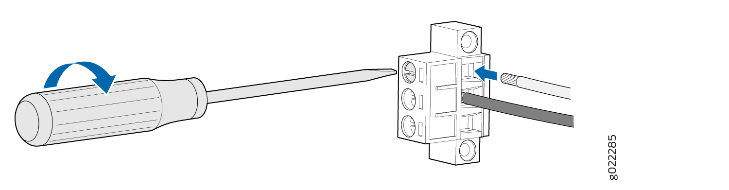
Secure the wire pins to the appropriate terminals on the terminal connector
by using the screws from the terminal connector (see Figure 4).
Figure 4: Securing Wire Pins to the Terminals on the Terminal Connector
-
To connect the wire pins to the appropriate terminals on the terminal connector:
-
Connect the positive (+) wire pin to the + terminal on the terminal connector.
-
Connect the negative (–) wire pin to the – terminal on the terminal connector.
-
Ensure that the pins are fully inserted into the terminal connector.
-
Use the screwdriver to tighten each screw on the terminal connector until snug. Do not overtighten. Apply 4.5 lb-in. (0.51 Nm) of torque to the screws.
-
-
-
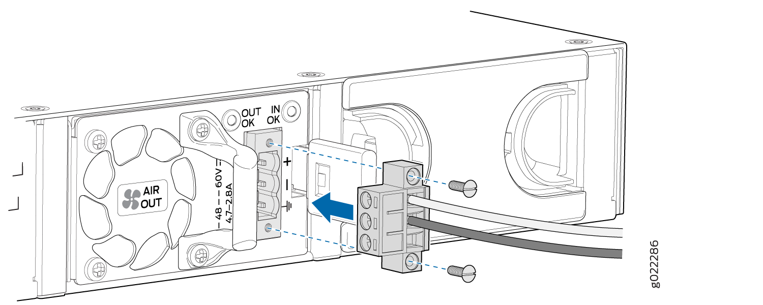
Insert the terminal connector (with the power cable attached) into the
power supply socket on the switch and secure it by tightening the two screws
on either side of the terminal connector (see Figure 5).
Figure 5: Securing the Terminal Connector to the DC Power Inlet
 Note:
Note:To supply sufficient power, terminate the DC input wiring on a facility DC source that is capable of supplying a minimum of 7.5 A at –48 VDC.