EX3400 Virtual Chassis
Planning EX3400 Virtual Chassis
Before interconnecting EX3400 switches in a Virtual Chassis configuration, you must consider the following factors:
The number of switches in the Virtual Chassis and their location—You can interconnect a maximum of 10 EX3400 switches to form a Virtual Chassis composed exclusively of EX3400 switches.
Mounting—You can mount the switches in a single rack or install them on multiple racks. For information about the size and strength of racks, see Rack Requirements.
Cabling requirements for Virtual Chassis—You can interconnect EX3400 switches into a Virtual Chassis by using the uplink ports configured as Virtual Chassis ports (VCPs). By default, the QSFP+ uplink ports are configured as VCPs.
For information about uplink port cabling requirements, see Management Cable Specifications.
Power requirements—You must plan the installation site to meet the power requirements of the switches in a Virtual Chassis. See Power Specifications for EX3400 Switches.
License requirements—You must have license keys for all the devices. See Understanding Software Licenses for EX Series Switches.
See Also
Understanding EX3400 Virtual Chassis Hardware Configuration
Virtual Chassis is a feature in Juniper Networks EX3400 Ethernet Switches that allows you to interconnect two or more EX3400 switches, enabling them to operate as a unified, single, high-bandwidth switch. You can interconnect a maximum of 10 EX3400 switches by using the uplink ports configured as Virtual Chassis ports (VCPs) to form a Virtual Chassis. By default, the QSFP+ uplink ports are configured as VCPs.
All EX3400 switch models support Virtual Chassis, and you can interconnect different models, which allows you to choose among a range of possible port configurations within the same Virtual Chassis.
The Virtual Chassis configuration includes a primary switch and a backup switch, with all other switches in the configuration designated as linecard member switches. Virtual Chassis operation is managed through the primary switch. Each switch in the Virtual Chassis is assigned a unique member ID.
Virtual Chassis Cabling Configuration Examples for EX3400 Switches
You can install EX3400 switches on a single rack or in multiple racks, or in different wiring closets, and interconnect them to form a Virtual Chassis.
You form an EX3400 Virtual Chassis by using uplink ports configured as Virtual Chassis ports (VCPs). By default, the QSFP+ uplink ports are configured as VCPs.
The physical location of the switches in a Virtual Chassis is restricted only by the maximum length supported for cables to connect the VCPs—in this case, the maximum length of the uplink port cables. For the maximum cable length for the uplink port cables supported by an EX3400 switch, see Pluggable Transceivers Supported on EX3400 Switches.
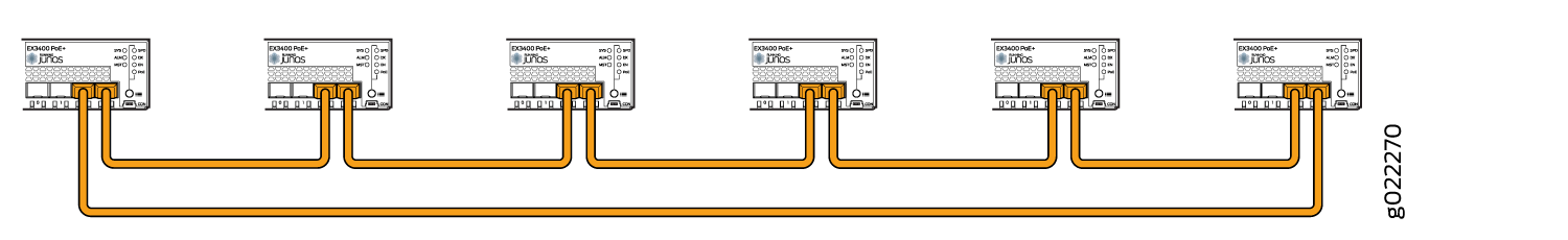
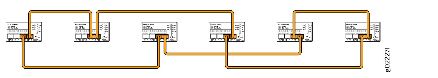
The following illustrations show examples of Virtual Chassis cabling configuration using SFP+ ports. The examples are applicable to configuration using QSFP+ ports also.
For increased availability and redundancy, we recommend that you always configure your Virtual Chassis in a ring topology.
Figure 1, Figure 2, and Figure 3 show six EX3400 switches stacked vertically in a rack and interconnected in a ring topology.
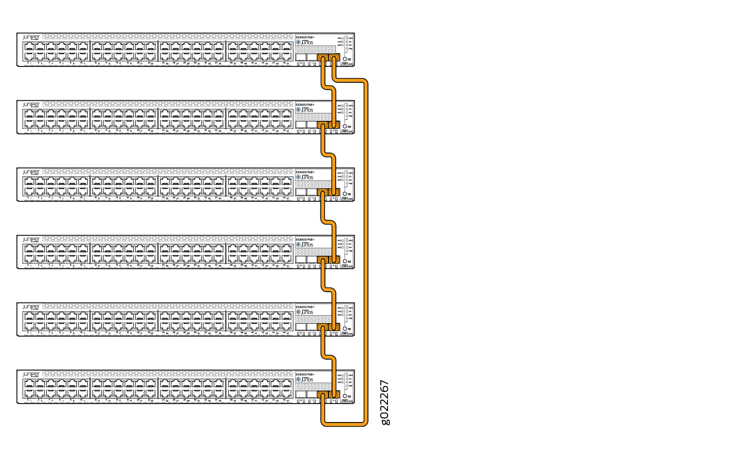
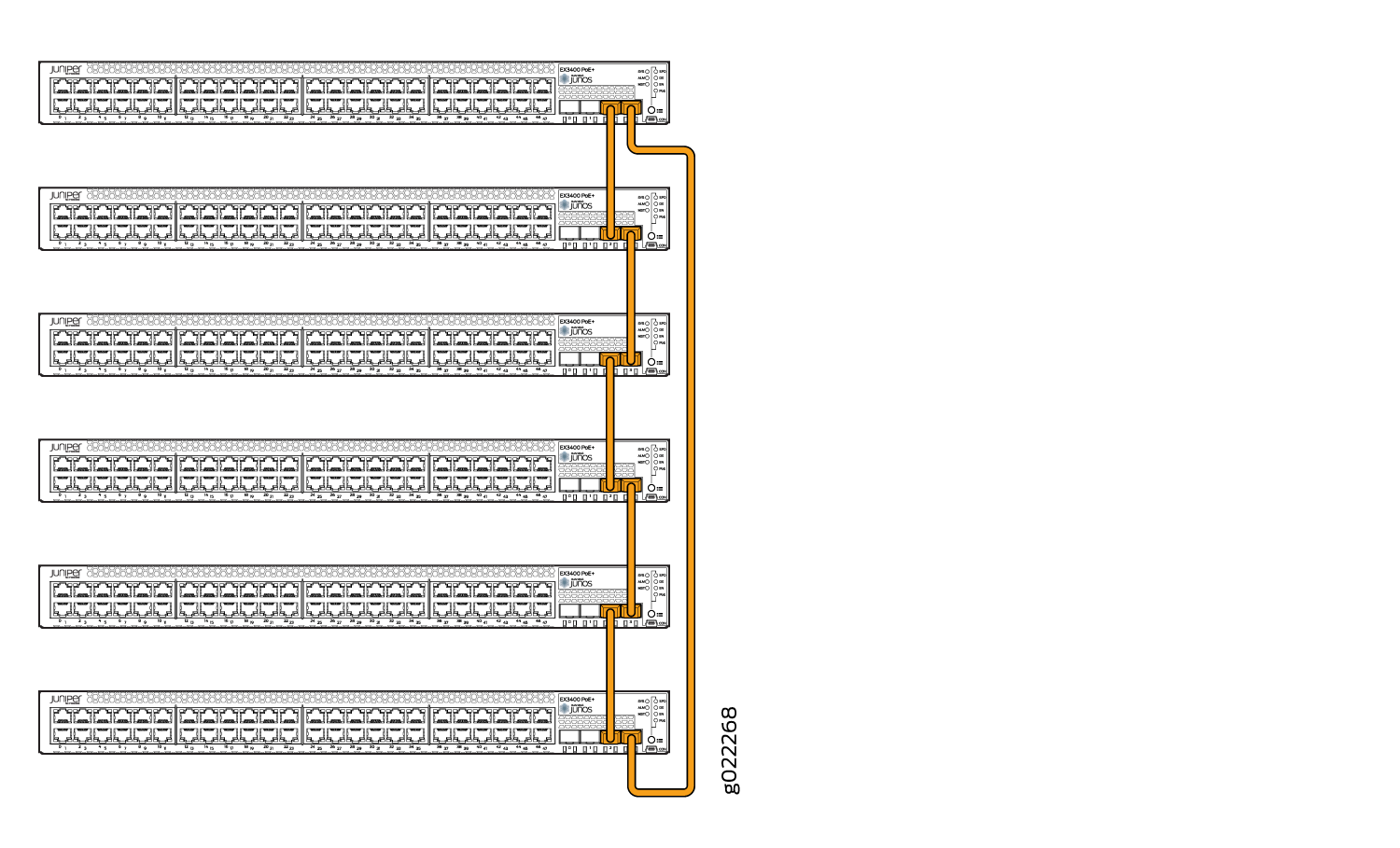
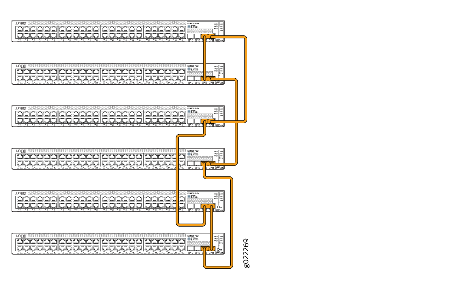
Figure 4 and Figure 5 show six EX3400 switches mounted on the top rows of adjacent racks and interconnected in a ring topology.