EX3400 Power System
AC Power Supply in EX3400 Switches
The AC power supplies in EX3400 switches are hot-insertable and hot-removable field-replaceable units (FRUs): You can install them without powering off the switch or disrupting the switching function. The switch is shipped with one power supply installed.
After powering on the switch, wait for at least 60 seconds before powering it off. After powering off the switch, wait for at least 60 seconds before powering it back on.
If only one power supply is installed in your EX3400 switch, you need to power off the switch before removing the power supply.
Table 1 lists the power consumed by each EX3400 switch model. The maximum power available on a PoE+ port is 30 W.
|
Model Number |
Number of PoE-Enabled Ports |
Maximum Power Consumed by the Switch |
Maximum System Power Available for PoE |
|---|---|---|---|
|
EX3400-24T |
– |
100 W |
– |
|
EX3400-24P |
24 |
110 W |
|
|
EX3400-48T |
– |
120 W |
– |
|
EX3400-48T-AFI |
– |
120 W |
– |
|
EX3400-48P |
48 |
120 W |
|
In EU countries, Egypt, Nigeria, Saudi Arabia, Serbia, South Korea, and South Africa, you must ensure that the redundant power supply is installed in the switch chassis.
Characteristics of a AC Power Supply
EX3400 switches support 150 W, 600 W, 920 W AC power supply. Power supplies are installed in the power supply slots labeled PSU 0 and PSU 1 in the rear panel of the chassis. The following table lists the details of the AC power supplies used in EX3400 switches.
|
Details |
150 W AC Power Supply |
150 W AC Power Supply |
600 W AC Power Supply |
920 W AC Power Supply |
|
|---|---|---|---|---|---|
|
Model number |
JPSU-150-AC-AFO |
JPSU-150-AC-AFI |
JPSU-600-AC-AFO |
JPSU-920-AC-AFO |
|
|
Field-replaceable unit (FRU) type |
Hot-insertable and hot-removable |
Hot-insertable and hot-removable |
Hot-insertable and hot-removable |
Hot-insertable and hot-removable |
|
|
Power supply weight |
1.433 lb (0.65 kg) |
1.433 lb (0.65 kg) |
1.82 lb (0.83 kg) |
1.87 lb (0.85 kg) |
|
|
Minimum installed in chassis |
1 |
1 |
1 |
1 |
|
|
Maximum installed in chassis |
2 |
2 |
2 |
2 |
|
|
Power supply slots |
Install in power supply slots in the rear panel of the chassis. |
Install in power supply slots in the rear panel of the chassis. |
Install in power supply slots in the rear panel of the chassis. |
Install in power supply slots in the rear panel of the chassis. |
|
|
Fans |
Internal |
Internal |
Internal |
Internal |
|
|
Airflow |
Front-to-back, indicated by label AIR OUT |
Back-to-front, indicated by label AIR IN |
Front-to-back, indicated by label AIR OUT |
Front-to-back, indicated by label AIR OUT |
|
|
Power supply status LEDs |
IN OK and OUT OK |
IN OK and OUT OK |
IN OK and OUT OK |
IN OK and OUT OK |
|
See Also
AC Power Supply LEDs in EX3400 Switches
Figure 1 shows the location of the LEDs on an AC power supply for an EX3400 switch.
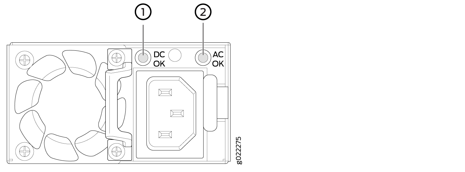
1 — DC OK LED | 2 — AC OK LED |
Table 3 describes the AC power supply LEDs.
|
LED |
Color |
Description |
|---|---|---|
|
AC OK |
Unlit |
Indicates one of the following:
|
|
Green |
Power supply is receiving proper input power. |
|
|
DC OK |
Unlit |
Indicates one of the following:
|
|
Green |
The power supply is delivering power and is functioning correctly. |
|
|
Red |
The power supply has failed and must be replaced. |
If the AC OK LED and the DC OK LED are not lit green, either the AC power cord is not installed properly or the power input voltage is not within normal operating range.
If the AC OK LED is lit green and the DC OK LED is unlit or lit red, the AC power supply is installed properly, but the power supply has an internal failure.
AC Power Cord Specifications for EX3400 Switches
A detachable AC power cord is supplied with the AC power supplies. The coupler is type C13 as described by International Electrotechnical Commission (IEC) standard 60320. The plug end of the power cord fits into the power source outlet that is standard for your geographical location.
The AC power cord provided with each power supply is intended for use with that power supply only and not for any other use.
In North America, AC power cords must not exceed 4.5 meters (approximately 14.75 feet) in length, to comply with National Electrical Code (NEC) Sections 400-8 (NFPA 75, 5-2.2) and 210-52 and Canadian Electrical Code (CEC) Section 4-010(3). The cords supplied with the switch are in compliance.
Table 4 gives the AC power cord specifications for the countries and regions listed in the table.
Country/Region |
Electrical Specifications |
Plug Standards |
Juniper Model Number |
|---|---|---|---|
Argentina |
250 VAC, 10 A, 50 Hz |
IRAM 2073 Type RA/3 |
CBL-EX-PWR-C13-AR |
Australia |
250 VAC, 10 A, 50 Hz |
AS/NZZS 3112 Type SAA/3 |
CBL-EX-PWR-C13-AU |
Brazil |
250 VAC, 10 A, 50 Hz |
NBR 14136 Type BR/3 |
CBL-EX-PWR-C13-BR |
China |
250 VAC, 10 A, 50 Hz |
GB 1002-1996 Type PRC/3 |
CBL-EX-PWR-C13-CH |
Europe (except Italy, Switzerland, and United Kingdom) |
250 VAC, 10 A, 50 Hz |
CEE (7) VII Type VIIG |
CBL-EX-PWR-C13-EU |
India |
250 VAC, 10 A, 50 Hz |
IS 1293 Type IND/3 |
CBL-EX-PWR-C13-IN |
Israel |
250 VAC, 10 A, 50 Hz |
SI 32/1971 Type IL/3G |
CBL-EX-PWR-C13-IL |
Italy |
250 VAC, 10 A, 50 Hz |
CEI 23-16 Type I/3G |
CBL-EX-PWR-C13-IT |
Japan |
125 VAC, 12 A, 50 Hz or 60 Hz |
JIS 8303 |
CBL-EX-PWR-C13-JP |
Korea |
250 VAC, 10 A, 50 Hz or 60 Hz |
CEE (7) VII Type VIIGK |
CBL-EX-PWR-C13-KR |
North America |
125 VAC, 13 A, 60 Hz |
NEMA 5-15 Type N5-15 |
CBL-EX-PWR-C13-US |
125 VAC, 15 A, 60 Hz |
NEMA 5-15 Type N5-15 |
CBL-PWR-C13-US-48P |
|
South Africa |
250 VAC, 10 A, 50 Hz |
SABS 164/1:1992 Type ZA/13 |
CBL-EX-PWR-C13-SA |
Switzerland |
250 VAC, 10 A, 50 Hz |
SEV 6534-2 Type 12G |
CBL-EX-PWR-C13-SZ |
Taiwan |
125 VAC, 11 A and 15 A, 50 Hz |
NEMA 5-15P Type N5-15P |
CBL-EX-PWR-C13-TW |
United Kingdom |
250 VAC, 10 A, 50 Hz |
BS 1363/A Type BS89/13 |
CBL-EX-PWR-C13-UK |
Figure 2 illustrates the plug on the power cord for some of the countries or regions listed in Table 4.
DC Power Supply in EX3400 Switches
The DC power supplies in EX3400 switches are hot-insertable and hot-removable field-replaceable units (FRUs): You can install them without powering off the switch or disrupting the switching function. The switch is shipped with one power supply installed.
After powering on the switch, wait for at least 60 seconds before powering it off. After powering off the switch, wait for at least 60 seconds before powering it back on.
If only one power supply is installed in your EX3400 switch, you need to power off the switch before removing the power supply.
Table 5 lists the power consumed by a DC-powered EX3400 switch model.
Model Number |
Number of PoE-Enabled Ports |
Maximum Power Consumed by the Switch |
Maximum System Power Available for PoE |
|---|---|---|---|
EX3400-24T-DC |
– |
110 W |
– |
EX3400-48T-DC |
– |
120 W |
– |
Characteristics of a DC Power Supply
EX3400 switches support 150 W DC power supply.
You can install up to two DC power supplies in an EX3400 switch. Power supplies are installed in the power supply slots labeled PSU 0 and PSU 1 in the rear panel of the chassis.
Table 6 lists the details of the power supplies used in EX3400 switches.
Details |
150 W DC Power Supply |
|
|---|---|---|
Model number |
JPSU-150-DC-AFO |
|
Field-replaceable unit (FRU) type |
Hot-insertable and hot-removable |
|
Power supply weight |
1.433 lb (0.65 kg) |
|
Minimum installed in chassis |
1 |
|
Maximum installed in chassis |
2 |
|
Power supply slots |
Install in power supply slots in the rear panel of the chassis. |
|
Fans |
Internal |
|
Airflow |
Front-to-back, indicated by label AIR OUT |
|
Power supply status LEDs |
IN OK and OUT OK |
|
To prevent electrical injury while installing or removing DC power supplies, carefully follow the instructions given in Installing a DC Power Supply in an EX3400 Switch and Removing a DC Power Supply from an EX3400 Switch.
DC Power Supply Airflow
Each power supply has its own fan and is cooled by its own internal cooling system.
Each power supply has a label AIR OUT on the faceplate of the power supply that indicates the direction of airflow in the power supply.
Table 7 lists the DC power supply models and the direction of airflow in them.
Model |
Label on Power Supply |
Direction of Airflow |
|---|---|---|
JPSU-150-DC-AFO |
AIR OUT |
Front-to-back—that is, air intake to cool the chassis is through the vents on the front panel of the chassis and hot air exhausts through the vents on the rear panel of the chassis. |
DC Power Supply LEDs in EX3400 Switches
Figure 3 shows the LEDs on a DC power supply for an EX3400 switch.
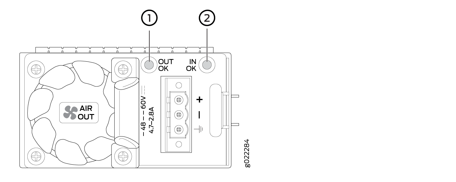
1 — OUT OK LED | 2 — IN OK LED |
Table 8 describes the LEDs on the DC power supplies.
|
Name |
Color |
Description |
|---|---|---|
|
IN OK |
Unlit |
Indicates one of the following:
|
|
Green |
The power supply is receiving power. |
|
|
OUT OK |
Unlit |
Indicates one of the following:
|
|
Green |
The power supply is functioning correctly. |
|
|
Red |
The power supply has failed and must be replaced. |
Power Specifications for EX3400 Switches
This topic describes the power supply electrical specifications for EX3400 switches.
Table 9 provides the AC power supply electrical specifications for EX3400 switches.
Item |
Specification |
|---|---|
AC input voltage |
100 through 240 VAC |
AC input line frequency |
50 Hz/60 Hz nominal |
AC system current rating |
|
Table 10 provides the DC power supply electrical specifications for EX3400 switches.
Item |
Specification |
|---|---|
DC input voltage |
–48 through –60 VDC |
DC input current rating |
4.7 A maximum at –48 VDC |
Power supply output |
150 W |
For DC power supplies, we recommend that you provide at least 4.7 A at 48 VDC and use a facility circuit breaker rated for 10 A minimum. Doing so enables you to operate the switch in any configuration without upgrading the power infrastructure, and enables the switch to function at full capacity using multiple power supplies.