Cooling System and Airflow in ACX7100-48L Routers
The cooling system in ACX7100-48L routers consists of six fan modules and a single fan in each power supply module (PSM). The ACX7100-48L routers can be set up with the following airflow directions:
-
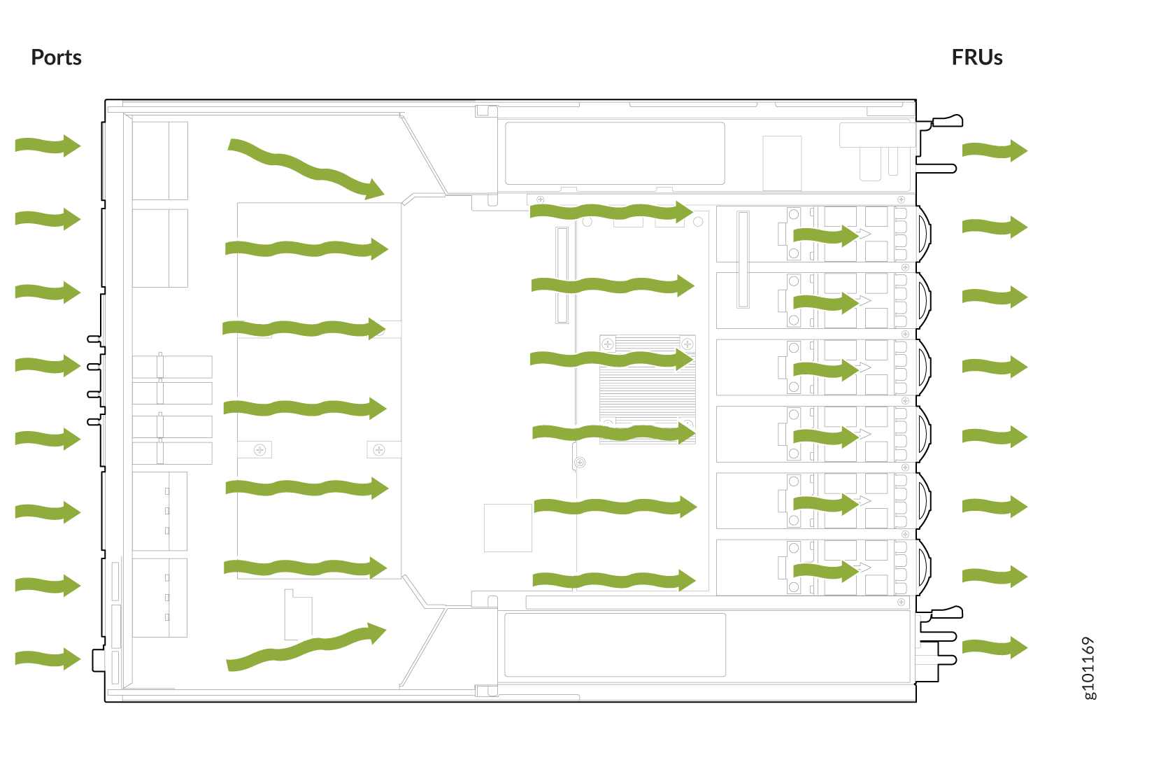
Air in (AI)—Air comes into the router through the vents in the field-replaceable units (FRUs).
-
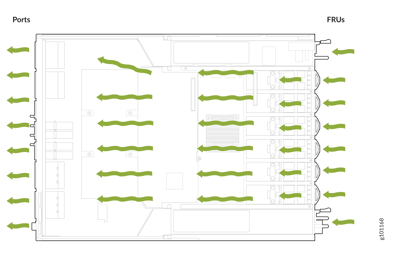
Air out (AO)—Air comes into the router through the vents in the front panel.
Do not use fan modules and PSMs with AIR OUT and AIR IN labels together in the same chassis.
Fan Modules
The fan modules in ACX7100-48L routers are hot-insertable and hot-removable field-replaceable units (FRUs). The fan modules are installed in the fan module slots on the rear of the router. The ACX7100-48L routers support six fan modules numbered 0 through 5 from left to right. Each fan module slot has a fan icon next to it.
The ACX7100-48L routers are available with either front-to-back airflow (airflow out, ports-to-FRUs, or AO) or back-to-front airflow (airflow in, FRUs-to-ports, or AI). In AO models, the air is pulled in through the front of the chassis toward the fan modules, from where it is exhausted out of the chassis. In AI models, the air is pulled in through the fan modules and toward the front of the chassis, from where it is exhausted out of the chassis. The fan modules and the power supply modules are available in both AO and AI models.
Figure 1 shows an ACX7100-48L AO fan module.
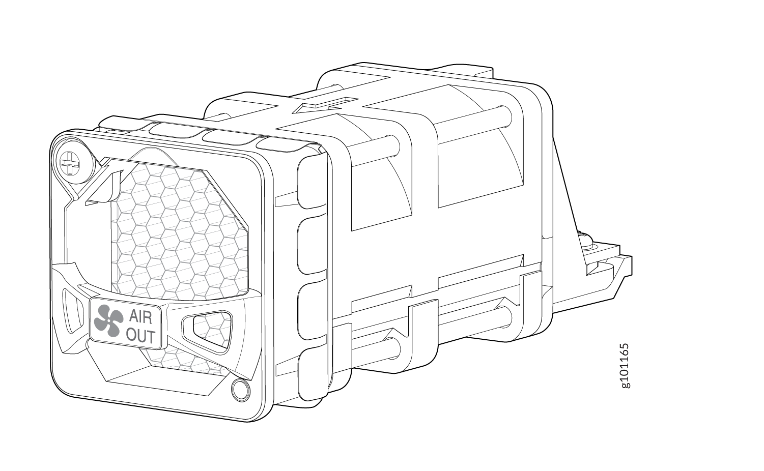
You remove and replace a fan module from the FRU end of the chassis. The router continues to operate for a limited period of time (240 seconds) during the replacement of the fan module without thermal shutdown.
All fan modules must be installed for optimal operation of the router.
Table 1 lists the available fan modules and the direction of airflow in them.
|
Fan Module |
Airflow Diagram |
Label on the Fan Module Handle |
Direction of Airflow in the Fan Module |
Power Supplies |
|---|---|---|---|---|
|
JNP7100-FAN1RU-AI |
AIR IN |
Air is pulled in through the fan modules and toward the front of the chassis, from where it is exhausted out of the chassis. |
You must install PSMs that have AIR IN labels only in those routers in which the fan modules have AIR IN labels. |
|
|
JNP7100-FAN1RU-AO |
AIR OUT |
Air is pulled in through the front of the chassis toward the fan modules, from where it is exhausted out of the chassis. |
You must install PSMs that have AIR OUT labels only in those routers in which the fan modules have AIR OUT labels. |
In data center deployments, position the router in such a manner that the AIR IN labels on the router components are facing the cold aisle, and the AIR OUT labels on the router components are facing the hot aisle.
Fan Module and Power Supply Requirements
Do not mix PSMs with different airflows. Ensure that the chassis is using either all airflow-in (AIR IN) models or all airflow-out (AIR OUT) models.
Similarly, ensure that all fan modules have the same airflow that matches the airflow of the PSMs. Mixing components with different airflows in the same chassis hampers the performance of the cooling system of the router and leads to overheating of the chassis. An alarm is raised if you install fan modules with different airflows in the chassis.
The system raises an alarm if a fan module fails, or if the ambient temperature inside the chassis rises above the acceptable range. If the temperature inside the chassis rises above the threshold temperature, the system shuts down automatically.
Do not mix fan modules. Use only the replacement fan modules that are designed for use with your product. See Table 1 for the correct part number for your ACX7100-48L router.
If you need to change the airflow direction in an ACX7100 router, you can change the airflow pattern. To convert an AIR IN product model to an AIR OUT product model, or an AIR OUT product model to an AIR IN product model, you must replace all of the fan modules and PSMs at one time to use the new airflow direction.
You must power off the device before replacing all the fans and power supply modules, and then power on the device. If you replace the fans or PSMs without powering off the device, the system raises an alarm.
Fan Status LEDs on ACX7100-48L Routers
You can check the status of the fan modules by using the show system alarms command, or by examining the LEDs next to
each fan module.
On the ACX7100-48L routers, the fan module LEDs are located on the chassis next to the fan module slot. Figure 4 shows the location of the fan module LEDs on an ACX7100-48L router.
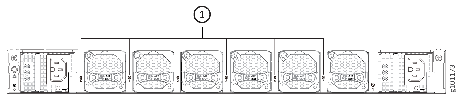
1 — Fan status LEDs |
Table 2 describes the function of the fan status LED.
|
Name |
Color |
State |
Description |
|---|---|---|---|
|
Fan status LED |
Green |
On steadily |
The fan module is operating normally. The system has verified that the module is engaged, that the airflow is in the correct direction, and that the fan is operating correctly. |
|
Red |
On steadily |
An error has been detected in the fan module. Replace the fan module as soon as possible. Either the fan has failed, or it is seated incorrectly. To maintain proper airflow through the chassis, leave the fan module installed in the chassis until you are ready to replace it. |
Under normal operating conditions, the fan modules operate at a moderate speed. Temperature sensors in the chassis monitor the temperature within the chassis.
The system raises an alarm if a fan module fails or if the ambient temperature inside the chassis rises above the acceptable range. If the ambient temperature rises, the fan speed increases to lower the ambient temperature. However, if the temperature inside the chassis rises above the threshold temperature, the system shuts down automatically.