ON THIS PAGE
ACX7100-48L Power System
AC Power Supply for ACX7100-48L Routers
The ACX7100-48L AC router operates at a maximum of 1600 W. The two power supply modules (PSMs) in ACX7100-48L routers are hot-removable and hot-insertable field-replaceable units (FRUs). The PSMs are preinstalled in the router. You can replace the PSMs without powering off the router or disrupting the router function.
Both the AI and AO PSMs look similar. Be sure to use the correct PSM for your chassis product model.
Do not mix PSMs with different airflow directions in the same chassis. The system raises an alarm when a PSM that has a different airflow direction is inserted into the chassis.
Do not use AC and DC PSMs together in the same chassis.
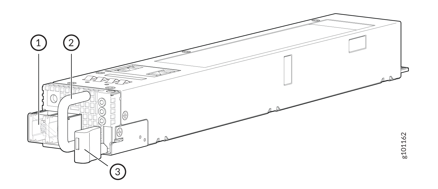
Figure 1 shows the AC PSM in ACX7100-48L routers.
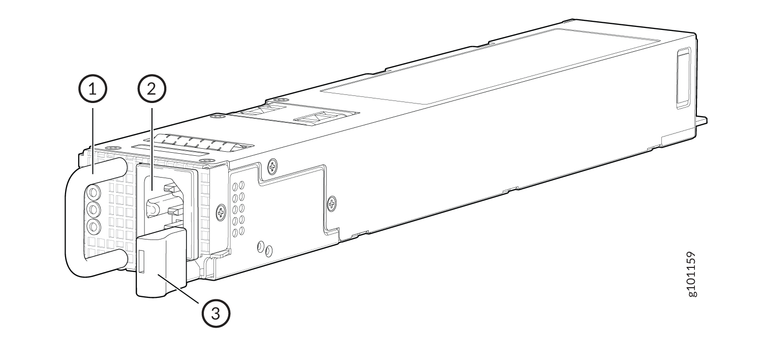
1 — Handle | 3 — Latch lever |
2 — AC inlet |
The PSMs provide FRU-to-port or port-to-FRU airflow, depending on the product model that you purchase.
Verify that the airflow direction on the PSM handle matches the direction of airflow in the chassis. Ensure that each PSM that you install in the chassis has the same airflow direction. If you install PSMs with different airflow directions, Junos raises an alarm. If you need to convert the airflow pattern on a chassis, you must replace all the fans and PSMs at one time to use the new direction.
Table 1 shows the different AC PSMs and their airflow direction for ACX7100-48L routers.
|
Power Supply Modules |
Wattage |
Direction of Airflow |
|---|---|---|
|
JPSU-1600W-1UACAFI |
1600 W |
Airflow in (back-to-front) |
|
JPSU-1600W-1UACAFO |
Airflow out (front-to-back) |
AC Power Specifications for ACX7100-48L Routers
Table 2 describes the AC power supply module (PSM) ratings and Table 3 describes the power consumption for ACX7100-48L routers.
Item |
Specifications for ACX7100-48L |
|---|---|
AC input voltage |
Operating range: 100 / 240 VAC |
AC input line frequency |
50–60 Hz |
AC input current rating |
13.6 A at 100-127 VAC 12.7 A at 115-127 VAC 9.4 A at 200-240 VAC |
|
Item |
Specifications |
|---|---|
|
Typical power consumption (at 25°C ambient temperature and without optics) |
570 W |
|
Maximum power consumption (at 40°C ambient temperature and without optics) |
960 W |
AC Power Cord Specifications for ACX7100-48L Routers
We ship detachable AC power cords with the chassis if you include them as part of your order. The coupler is type C15 as described by International Electrotechnical Commission (IEC) standard 60320. The plug end of the power cord fits into the power source outlet that is standard for your geographical location.
In North America, AC power cords must not exceed 4.5 meters in length to comply with National Electrical Code (NEC) Sections 400-8 (NFPA 75, 5-2.2) and 210-52 and Canadian Electrical Code (CEC) Section 4-010(3). The ACX Series power cords comply with the standards.
Table 4 lists the AC power cord specifications for each country or region.
Country/Region |
Electrical Specifications |
Plug Standards |
Juniper Model Number |
Spare Juniper Model Number |
Graphic |
|---|---|---|---|---|---|
Argentina |
250 VAC, 10 A, 50 Hz |
IRAM 2073 Type RA/3 |
– |
CBL-PWR-C15M-HITEMP-AR |
 |
Australia |
250 VAC, 10 A, 50 Hz |
AS/NZS 3112-2000 Type SAA/3 |
CG_CBL-C15-02-AU |
CBL-PWR-C15M-HITEMP-AU |
 |
Brazil |
250 VAC, 10 A, 50 Hz |
NBR 14136 Type BR/3 |
– |
CBL-PWR-C15M-HITEMP-BR |
 |
China |
250 VAC, 10 A, 50 Hz |
GB 2099/GB 1002 Type PRC/3 |
CG_CBL-C15-02-CH |
CBL-PWR-C15M-HITEMP-CH |
 |
Europe (except Italy, Switzerland, and United Kingdom) |
250 VAC, 10 A, 50 Hz |
CEE (7) VII Type VIIG |
CG_CBL-C15-02-EU |
CBL-PWR-C15M-HITEMP-EU |
 |
Italy |
250 VAC, 10 A, 50 Hz |
CEI 23-16 Type I/3G |
CG_CBL-C15-02-IT-CH |
CBL-PWR-C15M-HITEMP-IT |
 |
Japan |
125 VAC, 15 A, 50 Hz |
JIS 8303 Type 498GJ |
CG_CBL-C15-02-JP |
CBL-PWR-C15M-HITEMP-JP |
 |
North America |
125 VAC, 15 A, 50 Hz |
NEMA 5-15 Type 498G |
CG_CBL-C15-02-US |
CBL-PWR-C15M-HITEMP-US |
|
South Africa and India |
250 VAC, 10 A, 50 Hz |
SABS 164/1:1992 Type ZA/3 |
– |
CBL-PWR-C15M-HITEMP-SA |
 |
South Korea and some parts of Europe |
250 VAC, 10 A, 50 Hz |
CEE(7) VII Type VIIG |
– |
CBL-PWR-C15M-HITEMP-KR |
|
Switzerland |
250 VAC, 10 A, 50 Hz |
SEV 1011/6534-2 Type 12G |
CG_CBL-C15-02-SZ |
CBL-PWR-C15M-HITEMP-SZ |
 |
United Kingdom |
250 VAC, 10 A, 50 Hz |
BS 1363/A Type BS89/13 |
CG_CBL-C15-02-UK |
CBL-PWR-C15M-HITEMP-UK |
|
AC Power Supply Module LEDs on ACX7100-48L Routers
The AC power supply module (PSM) on an ACX7100-48L router uses three LEDs to indicate power status. Figure 2 shows the location of the LEDs on the AC PSM.
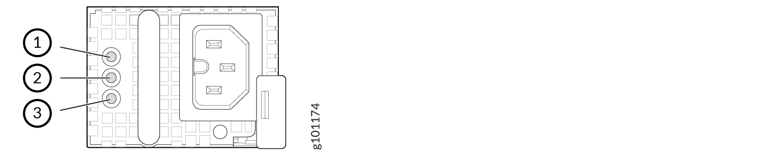
1 — AC Input status LED | 3 — Fault LED |
2 — DC Output status LED |
Table 5 describes the LEDs on the AC PSM.
LED |
Color |
State |
Description |
|---|---|---|---|
AC input status LED |
Unlit |
Off |
The PSM is disconnected from power, or there is no input power to the PSM. |
Green |
On steadily |
There is input AC power supply to the PSM. |
|
DC output status LED |
Unlit |
Off |
There is no output voltage from the PSM. Check the PSM. |
Green |
On steadily |
There is output voltage from the PSM. |
|
Fault LED |
Amber |
On steadily |
An error is detected in the PSM. Replace the PSM as soon as possible. To maintain proper airflow through the chassis, leave the PSM installed in the chassis until you are ready to replace it. |
Blinking |
The PSM is an invalid model. |
DC Power Supply for ACX7100-48L Routers
The two power supply modules (PSMs) in ACX7100-48L routers are hot-removable and hot-insertable field-replaceable units (FRUs). The PSMs are preinstalled in the router. The DC power supply in ACX7100-48L is 1600 W with dual feeds for power resiliency. You can install replacement PSMs without powering off the router or disrupting the router function.
Both the AI and AO PSMs look similar. Be sure to use the correct PSM for your chassis product model.
Do not mix PSMs with different airflow directions. The system raises an alarm when a PSM that has a different airflow direction is inserted into the chassis.
Figure 3 shows the DC PSM in ACX7100-48L routers.
1 — Terminal block cover | 3 — Latch lever |
2 — Handle |
Table 6 shows the different PSMs and their airflow direction for ACX7100-48L routers.
|
Power Supply Module Number |
Wattage |
Direction of Airflow |
|---|---|---|
|
JPSU-1600W-1UDCAFI |
1600 W |
Airflow in (back-to-front) |
|
JPSU-1600W-1UDCAFO |
Airflow out (front-to-back) |
DC Power Specifications for ACX7100-48L Routers
Table 7 describes the DC power supply module (PSM) ratings and Table 8 describes the power consumption for ACX7100-48L routers.
Item |
Specifications for ACX7100-48L |
|---|---|
DC input voltage |
|
DC input line current |
27.5 A maximum |
|
Item |
Specifications |
|---|---|
|
Typical power consumption (at 25°C ambient temperature and without optics) |
570 W |
|
Maximum power consumption (at 40°C ambient temperature and without optics) |
960 W |
DC Power Supply Module LEDs on ACX7100-48L Routers
Figure 4 shows the location of the LEDs on the DC power supply module (PSM).
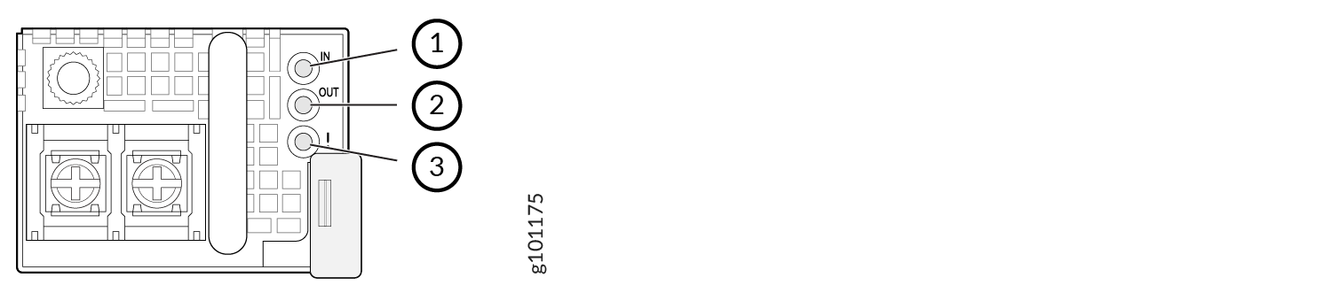
1 — Input LED (IN) | 3 — Fault LED (!) |
2 — Output LED (OUT) |
Table 9 describes the LEDs on the DC PSMs.
Name |
Color |
State |
Description |
|---|---|---|---|
IN (input) |
Unlit |
Off |
There is no input power to the PSM. |
Green |
On steadily |
There is input DC power to the PSM. |
|
OUT (output) |
Unlit |
Off |
There is no output voltage from the PSM. Check the PSM. |
Green |
On steadily |
There is output voltage from the PSM. |
|
! (fault) |
Amber |
On steadily |
An error is detected in the PSM. Replace the PSM as soon as possible. To maintain proper airflow through the chassis, leave the PSM installed in the chassis until you are ready to replace it. |