ON THIS PAGE
Chassis Physical Specifications for ACX7024 and ACX7024X Routers
Environmental Requirements and Specifications for ACX7024 Routers
Environmental Requirements and Specifications for ACX7024X Routers
Grounding Cable and Lug Specifications for ACX7024 and ACX7024X Routers
Clearance Requirements for Hardware Maintenance of ACX7024 and ACX7024X Routers
ACX7024 and ACX7024X Site Guidelines and Requirements
General Site Guidelines
Efficient device operation requires proper site planning. For the device to operate properly, you must ensure maintenance and proper layout of the equipment, rack or cabinet, and wiring closet.
To plan and create an acceptable operating environment for your device and prevent environmentally caused equipment failures:
Keep the area around the chassis free from dust and conductive material, such as metal flakes.
Follow the prescribed airflow guidelines to ensure that the cooling system functions properly. Ensure that the exhaust from other equipment does not blow into the intake vents of the device.
Follow the prescribed electrostatic discharge (ESD) prevention procedures to prevent damaging the equipment. Static discharge can cause components to fail completely or intermittently over time.
Install the device in a secure area, so that only authorized personnel can access the device.
ACX7024 and ACX7024X Site Electrical Wiring Guidelines
Table 1 describes the factors you must consider while planning the electrical wiring at your site.
You must provide a properly grounded and shielded environment and use electrical surge-suppression devices.
Avertissement Vous devez établir un environnement protégé et convenablement mis à la terre et utiliser des dispositifs de parasurtension.
|
Site Wiring Factor |
Guidelines |
|---|---|
|
Signaling limitations |
If your site experiences any of the following problems, consult experts in electrical surge suppression and shielding:
|
|
Radio frequency interference |
To reduce or eliminate RFI from your site wiring, do the following:
|
|
Electromagnetic compatibility |
If your site is susceptible to problems with electromagnetic compatibility (EMC), particularly from lightning or radio transmitters, seek expert advice. Strong sources of electromagnetic interference (EMI) can cause:
|
The intrabuilding port(s) (MGMT and CON ports) of the equipment or subassembly must use shielded intrabuilding cabling or wiring that is grounded at both ends.
Chassis Physical Specifications for ACX7024 and ACX7024X Routers
The ACX7024 and ACX7024X router chassis is a rigid sheet-metal structure that houses the hardware components. Table 2 summarizes the physical specifications of an ACX7024 and ACX7024X router and its components.
|
Item |
Height |
Width |
Depth |
Weight |
|---|---|---|---|---|
|
ACX7024 and ACX7024X |
1.75 in. (4.4 cm) |
19 in. (48.2 cm) |
9.6 in. (24.4 cm) |
|
|
PSM |
1.57 in. (4.0 cm) |
1.97 in. (5.0 cm) |
9.0 in. (23.0 cm) |
1.3 lb (0.59 kg) |
Environmental Requirements and Specifications for ACX7024 Routers
You must install the router in a rack or cabinet. To ensure proper functioning of the router, house it in a dry, clean, well-ventilated, and temperature-controlled environment.
Follow these environmental guidelines:
-
Keep the site as dust-free as possible. Dust can clog air intake vents and filters, reducing the efficiency of the router cooling system.
-
Maintain ambient airflow for normal router operation. If the airflow is blocked or restricted, or if the intake air is too warm, the router might overheat and the router temperature monitor might shut down the device to protect the hardware components.
-
For outside plant installation (OSP) or indoor non-office environment, you must protect the router against dust, fog, salt fog, pests, moisture, and other airborne contaminants. For OSPs, we recommend that you install the device in a sealed cabinet such as an IP65 cabinet with heat exchanger. The cabinet must also comply with Telcordia GR487 specification.
Note:The sealed cabinet should always remain closed. However, if the cabinet door is opened for any maintenance service, ensure that the door remains open only for the minimum required service time. If the cabinet door remains open for an extended period, outside contaminants (such as dust and moisture) can enter the cabinet and affect the functioning of the device within the cabinet.
Table 3 provides the required environmental conditions for normal router operation.
|
Description |
Tolerance |
|---|---|
|
Altitude |
No performance degradation up to 6000 feet (1,829 meters) |
|
Relative humidity |
Normal operation ensured in relative humidity range of 5% through 90%, noncondensing. |
|
Temperature |
|
Environmental Requirements and Specifications for ACX7024X Routers
You must install the router in a rack or cabinet. To ensure proper functioning of the router, house it in a dry, clean, well-ventilated, and temperature-controlled environment.
Follow these environmental guidelines:
-
Keep the site as dust-free as possible. Dust can clog air intake vents and filters, reducing the efficiency of the router cooling system.
-
Maintain ambient airflow for normal router operation. If the airflow is blocked or restricted, or if the intake air is too warm, the router might overheat and the router temperature monitor might shut down the device to protect the hardware components.
Table 4 provides the required environmental conditions for normal router operation.
|
Description |
Tolerance |
|---|---|
|
Altitude |
No performance degradation up to 6000 feet (1,829 meters) |
|
Relative humidity |
Normal operation ensured in relative humidity range of 5% through 90%, noncondensing. |
|
Temperature |
|
Grounding Cable and Lug Specifications for ACX7024 and ACX7024X Routers
For installations that require a separate grounding conductor to the chassis, you must ground the router properly before you connect power. Grounding ensures proper operation and satisfies safety and electromagnetic interference (EMI) requirements. To ground an ACX7024 or ACX7024X router, connect a grounding cable to earth ground, and then attach the grounding cable to the chassis grounding points.
The grounding points are in the form of studs that are sized for #10–32 screws.
Before you install the router, a licensed electrician must attach a cable lug to the grounding cables that you supply. See Connect Earth Ground to ACX7024 or ACX7024X Routers. A cable with an incorrectly attached lug can damage the router.
The ACX7024 and ACX7024X router uses an LCD6-10A-L grounding lug and the grounding lug accommodates a 6 AWG, 90 °C stranded copper wire (green with yellow insulation), or as required by local electric code.
Clearance Requirements for Hardware Maintenance of ACX7024 and ACX7024X Routers
When planning the site for installing an ACX7024 or ACX7024X router, you must allow sufficient clearance around the installed chassis (see Figure 1).
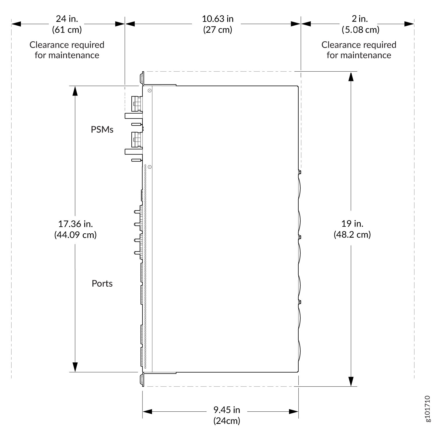
-
For the cooling system to function properly, the airflow around the chassis must be unrestricted. See Cooling System and Airflow in ACX7024 and ACX7024X Routers for more information about the airflow through the chassis.
-
If you are mounting an ACX7024 or ACX7024X router in a rack that has other equipment installed, ensure that the exhaust from other equipment does not blow into the intake vents of the chassis.
Rack Requirements for ACX7024 and ACX7024X Routers
We've designed the ACX7024 and ACX7024X routers to be installed on two-post racks. Table 5 provides the rack requirements and specifications for ACX7024 and ACX7024X routers.
|
Rack Requirement |
Guidelines |
|---|---|
|
Rack type |
Use a two-post rack that provides bracket holes or hole patterns spaced at 1-U (1.75 in. or 4.45 cm) increments and meets the size and strength requirements to support the weight. A U is the standard rack unit defined by the Electronic Components Industry Association (http://www.ecianow.org). |
|
Mounting bracket hole spacing |
The holes in the mounting brackets are spaced at 1-U (1.75 in. or 4.45 cm), so that you can mount the device in any rack that provides holes that are spaced at that distance. |
|
Rack size and strength |
|
|
Securing rack to building structure |
|
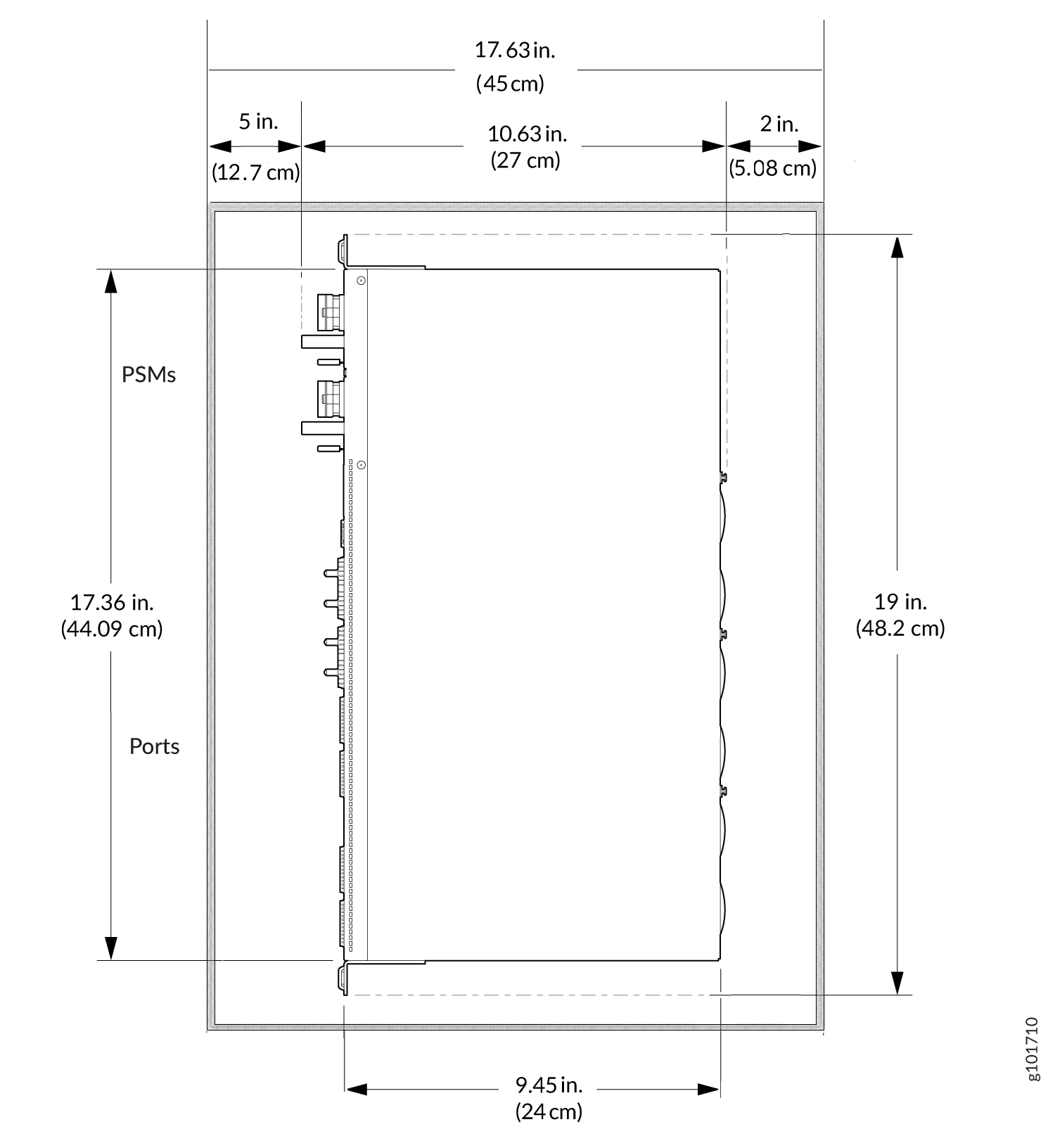
Cabinet Requirements for ACX7024 and ACX7024X Routers
Table 6 provides the cabinet requirements and specifications.
|
Cabinet Requirement |
Guidelines |
|---|---|
|
Cabinet size and clearance |
The cabinet must have a minimum clearance of 2 in. (5.08 cm) between the router's rear panel and the inner surface of the rear door, and at least 5 in. (12.7 cm) between the PSM handle on the front panel and the inner surface of the front door. |
|
Type and strength |
Inside the cabinet, use a two-post rack that provides bracket holes or hole patterns spaced at 1-U (1.75 in. or 4.45 cm) increments and meets the size and strength requirements to support the weight. A U is the standard rack unit defined by the Electronic Components Industry Association (http://www.ecianow.org). |
|
Cabinet airflow requirements |
When you mount the device in a cabinet, ensure that ventilation through the cabinet is sufficient to prevent overheating.
|
|
Securing cabinet to building structure |
|