Help us improve your experience.

Let us know what you think.

Do you have time for a two-minute survey?


Connect ACX7024 or ACX7024X to Power

Connect Earth Ground to ACX7024 or ACX7024X Routers

Before you begin to connect the router to earth ground, ensure that you have the following parts and tools available:

  • A grounding cable—6 AWG, 90° C stranded copper wire (green with yellow insulation), or as required by local electric code.
  • Two #10-32 grounding screws to secure the grounding lug
  • LCD6 2-hole grounding lug
  • A Phillips (+) screwdriver, number 2 (not provided)
  • An electrostatic discharge (ESD) grounding wrist strap

To meet safety and electromagnetic interference (EMI) requirements and to ensure proper operation, you must ground the router properly before connecting power.

You must install the ACX7024 or ACX7024X in a restricted-access location and ensure that the chassis is always properly grounded. The ACX7024 and ACX7024X routers have a two-hole protective grounding terminal provided on the chassis. See Figure 2. Under all circumstances, use this grounding connection to ground the chassis. For AC-powered systems, you must also use the grounding wire in the AC power cord along with the two-hole grounding lug connection. This tested system meets or exceeds all applicable EMC regulatory requirements with the two-hole protective grounding terminal.

Before you connect earth ground to the protective earthing terminal of ACX7024 and ACX7024X routers, ensure that a licensed electrician has attached an appropriate grounding lug to the grounding cable.

Figure 1 shows the grounding point on ACX7024 and ACX7024X routers.
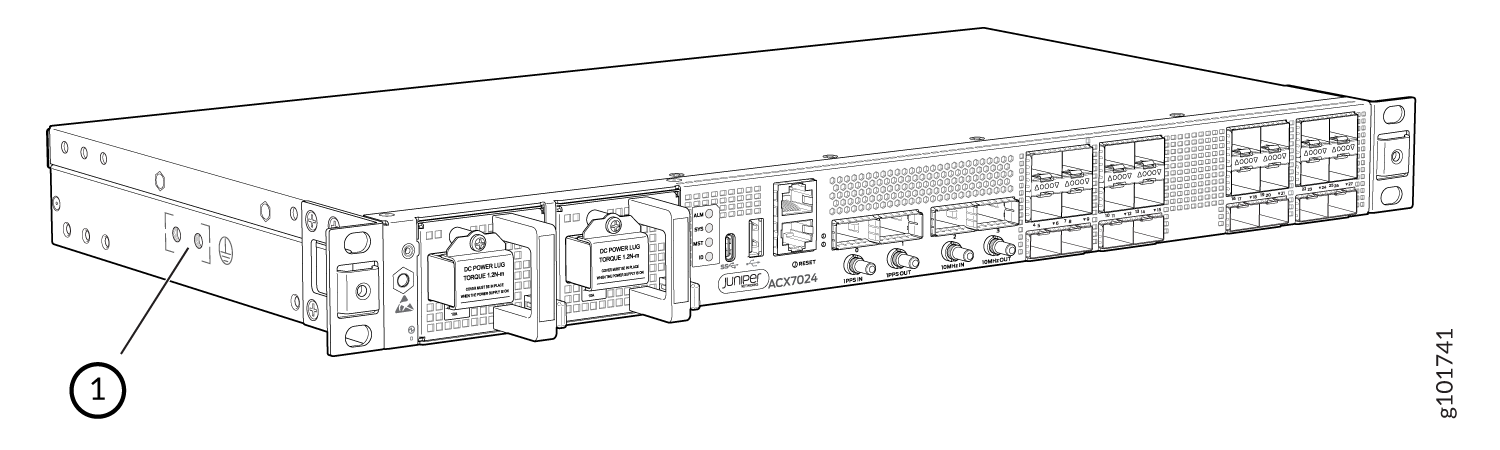
Figure 1: Grounding Point on the ACX7024 and ACX7024X Routers Grounding Point on the ACX7024 and ACX7024X Routers
  1
Grounding point
 

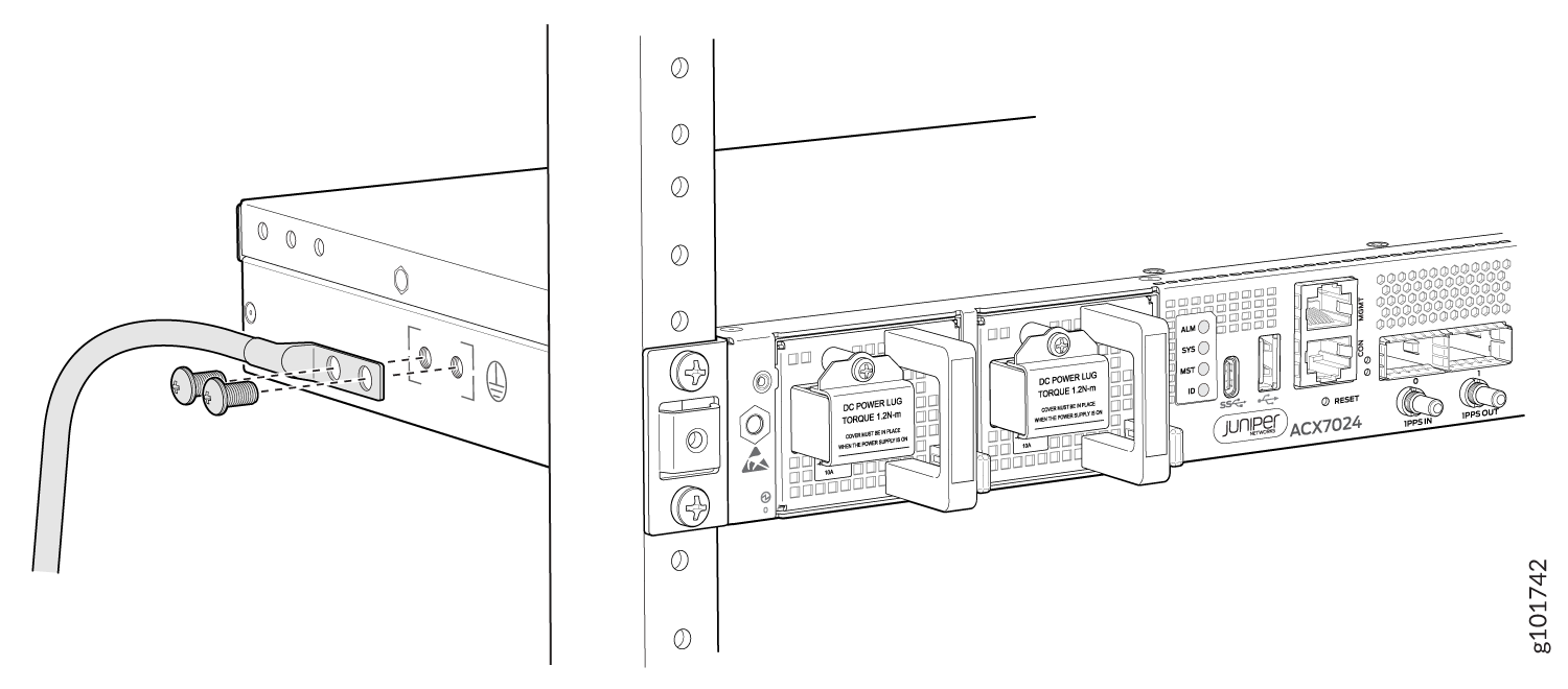
To ground the ACX7024 and ACX7024X routers:

  1. Verify that a licensed electrician has attached the cable lug that is provided with the router to the grounding cable.
  2. Ensure that all grounding surfaces are clean and brought to a bright finish before you make grounding connections.
  3. Connect the grounding cable to a proper earth ground.
  4. Place the grounding cable lug over the grounding points on the side of the chassis (see Figure 2 ).
    Figure 2: Connect the Grounding Cable to the ACX7024 or ACX7024X Router Connect the Grounding Cable to the ACX7024 or ACX7024X Router
  5. Secure the grounding cable lug with the screws. Apply 2.5 N-m of torque to the screws.
  6. Dress the grounding cable and verify that it does not touch or block access to router components, and that it does not drape where people could trip over it.

Connect AC Power to an ACX7024 or ACX7024X Router

Ensure that you have a power cord appropriate for your geographical location available to connect AC power to the router.

Before you begin connecting AC power to the router:

  • Ensure that you have taken the necessary precautions to prevent electrostatic discharge (ESD) damage (see Prevention of Electrostatic Discharge Damage).

  • Ensure that you have connected the router chassis to earth ground.

    CAUTION:

    Before you connect power to the router, a licensed electrician must attach a cable lug to the grounding and power cables that you supply. A cable with an incorrectly attached lug can damage the router (for example, by causing a short circuit).

    To meet safety and electromagnetic interference (EMI) requirements and to ensure proper operation, you must connect the chassis to earth ground before you connect it to power. Under all circumstances, use the protective earthing terminal on the router chassis to connect to the earth ground. The router gains additional grounding when you plug the PSM in the router to a grounded AC power outlet by using the AC power cord appropriate for your geographical location.

  • Install the PSM in the chassis.

The power supply module (PSM) in an ACX7024 and ACX7024X router is a hot-removable and hot-insertable field-replaceable unit (FRU). You can remove and replace it without powering off the router or disrupting routing functions.

Note:

You must connect each PSM to a dedicated power source outlet.

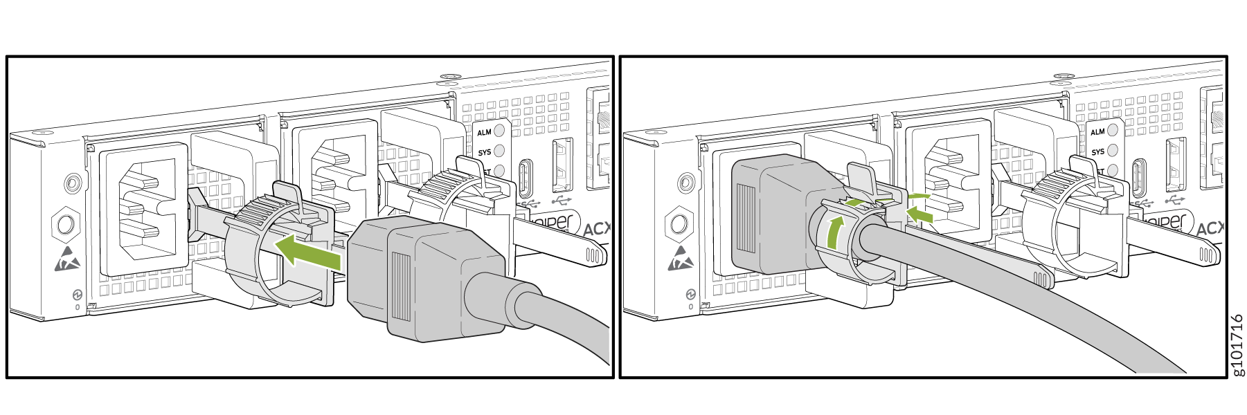
To connect AC power to an ACX7024 or ACX7024X router:

  1. Wrap and fasten one end of the ESD grounding strap around your bare wrist, and connect the other end of the strap to the ESD point on the chassis.
  2. Power off the AC input appliance inlet on the source power supply.
  3. Connect the power cord to the power source outlet.
    Note:

    Each power supply must be connected to a dedicated AC power feed and a dedicated customer-site 2-pole circuit breaker. We recommend that you use a dedicated customer-site circuit breaker rated for 16A, or as required by local code.

  4. Press the small tab on the power cord retainer strip to loosen the loop. Slide the loop until you have enough space to insert the power cord coupler into the inlet.
  5. Insert the power cord coupler firmly into the inlet.
  6. Slide the loop toward the PSM until it is snug against the base of the coupler.
  7. Press the tab on the loop and draw out the loop into a tight circle (see Figure 3).
  8. Route the power cord appropriately. Verify that the power cord does not block the air exhaust and access to router components, or drape where people could trip over it.
  9. Power on the source power supply.
  10. Repeat Step 4 through Step 9 for installing the remaining PSM.
    Figure 3: Connect an AC power cord to an ACX7024 or ACX7024X Router Connect an AC power cord to an ACX7024 or ACX7024X Router

Connect DC Power to an ACX7024 or ACX7024X Router

Before you begin connecting DC power to the router:

  • Ensure that you have taken the necessary precautions to prevent electrostatic discharge (ESD) damage (see Prevention of Electrostatic Discharge Damage).

  • Ensure that you have connected the router chassis to earth ground.

    CAUTION:

    Before you connect power to the router, a licensed electrician must attach a cable lug to the grounding and power cables that you supply. A cable with an incorrectly attached lug can damage the router (for example, by causing a short circuit).

    To meet safety and electromagnetic interference (EMI) requirements and to ensure proper operation, you must connect the chassis to earth ground before you connect it to power. Under all circumstances, use the protective earthing terminal on the router chassis to connect to the earth ground.

  • Install the power supply module (PSM) in the chassis.

Ensure that you have the following parts and tools available:

  • Two DC power source cables (16 AWG wire or as required by local electric code)

  • An electrostatic discharge (ESD) grounding wrist strap

  • Phillips (+) screwdriver, number 2 (not provided) for tightening screws on the PSM terminals.

  • Phillips (+) screwdriver, number 1 (not provided) for tightening the terminal cover screws.

  • Multimeter (not provided)

The PSM in an ACX7024 and ACX7024X router is a hot-removable and hot-insertable field-replaceable unit (FRU). You can remove and replace it without powering off the router or disrupting routing functions.

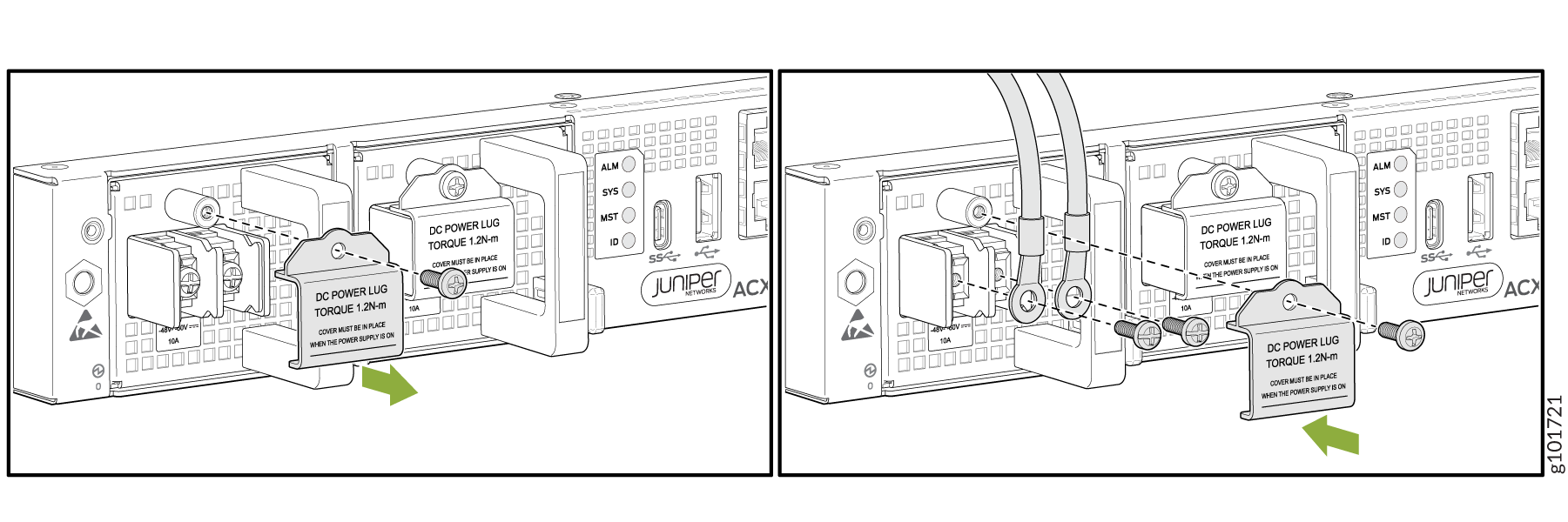
To connect DC power to an ACX7024 or ACX7024X router:

  1. Wrap and fasten one end of the ESD grounding strap around your bare wrist. Connect the other end of the strap to the ESD point on the chassis.
  2. Verify that the DC power cables are correctly labeled before making connections to the power supply. In a typical power distribution scheme where the return is connected to chassis ground at the battery plant, you can use a multimeter to verify the resistance of the –48 V and RTN DC cables to chassis ground:
    • The cable with very low resistance (indicating a closed circuit) to chassis ground is positive (+). You install this cable on the V+ (return) DC power input terminal.

    • The cable with very high resistance (indicating an open circuit) to chassis ground is negative (–). You install this cable on the V– (input) DC power input terminal.

    CAUTION:

    You must ensure that power connections maintain the proper polarity. The power source cables might be labeled (+) and (–) to indicate their polarity. There is no standard color coding for DC power cables. Use the color coding that you see on the external DC power source at your site to determine the color coding for the leads on the power cables that attach to the DC power input terminals on each PSM.

  3. Install heat-shrink tubing insulation around the power cables.

    To install heat-shrink tubing:

    1. Slide the tubing over the portion of the cable where it is attached to the lug barrel. Ensure that tubing covers the end of the wire and the barrel of the lug attached to it.

    2. Shrink the tubing with a heat gun. Ensure that you heat all sides of the tubing evenly so that it shrinks around the cable tightly.

    Figure 4 shows the steps to install heat-shrink tubing.

    Note:

    Do not overheat the tubing.

    Figure 4: How to Install Heat-Shrink Tubing
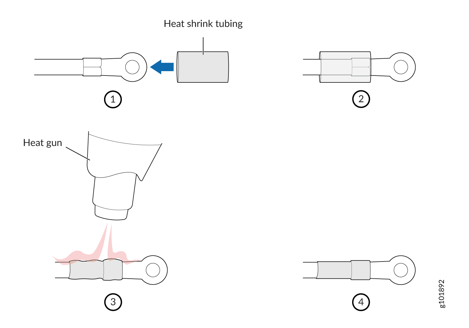
 How to Install Heat-Shrink Tubing
  4. Ensure that the input circuit breaker is open so that the voltage across the DC power source cable leads is 0 V and that the cable leads do not become active while you are connecting DC power.
    Note:

    The V+ terminals are referred to as +RTN, and V– terminals are referred to as –48 V in DC Power Wiring Sequence Warning.

  5. Ensure that the PSMs are fully inserted in the chassis.
  6. Remove the terminal block cover protecting the terminals on the faceplate (see Figure 5).
  7. Remove the screws on the terminals by using the Phillips number 2 screwdriver. Save the screws.
    Warning:

    Ensure that the power cables do not block access to device components or drape where people can trip over them.

  8. Connect each PSM to the power sources. Secure power source cables to the PSMs by screwing the ring lugs attached to the cables to the appropriate terminals by using the screw from the terminals (see Figure 5).

    The ACX7024 and ACX7024X router is designed to operate with a DC PSM that has a single, nonredundant, feed input. For source redundancy, you must install two DC PSMs in the ACX7024 and ACX7024X; connect source (A) to one PSM and source (B) to the second PSM. This configuration provides the commonly deployed A/B feed redundancy for the system.

    CAUTION:

    The connection between each power source and PSM must include a circuit breaker. We recommend that you use a customer-site 2-pole circuit breaker rated for 10A, or as required by local electrical code.

    Do not connect two sources to a single PSM because doing so can potentially cause circulating current in feed wires whenever there is any difference in the voltage of the two sources.

    Note:

    To connect the DC source or DC mains to an ACX7024 or ACX7024X router, use a 16 AWG wire or as required by local electric code.

    1. Secure the ring lug of the positive (+) DC power source cable to the RTN (return) terminal on the DC PSM.
    2. Secure the ring lug of the negative (–) DC power source cable to the –48V (input) terminal on the DC PSM.
    3. Tighten the screws on the PSM terminals until snug using the Phillips number 2 screwdriver. Do not overtighten—apply 1.2 N-m of torque to the screws.
      Note:

      After you crimp the input DC wires to its wiring lugs, cover the lugs and crimped area with a suitable heat shrink sleeve. The heat shrink sleeve prevents bare lugs or crimped areas from being exposed.

  9. Replace the terminal block cover. Apply 0.5 N-m of torque to the screws.
  10. Close the input circuit breaker.
    Note:

    The switch powers on as soon as the PSM receives power. There is no power switch on the device.

Figure 5: Connect DC Power Cable to an ACX7024 or ACX7024X Router Connect DC Power Cable to an ACX7024 or ACX7024X RouterCan we use callouts to show the parts clearly?