Maintaining the ACX7024 and ACX7024X Power Supplies
Replace an ACX7024 or ACX7024X Power Supply Module
- Remove an ACX7024 or ACX7024X AC Power Supply Module
- Install an ACX7024 or ACX7024X AC Power Supply Module
- Remove an ACX7024 or ACX7024X DC Power Supply Module
- Install an ACX7024 or ACX7024X DC Power Supply Module
Remove an ACX7024 or ACX7024X AC Power Supply Module
Before you remove a PSM from a router, ensure that you have taken the necessary precautions to prevent electrostatic discharge (ESD) damage (see Prevention of Electrostatic Discharge Damage).
Ensure that you have the following parts and tools available to remove a PSM from a router:
-
ESD grounding strap
-
Antistatic bag or an antistatic mat
The power supply modules (PSMs) in ACX7024 and ACX7024X routers are hot-removable and hot-insertable field-replaceable units (FRUs). You can remove and replace the PSMs without powering off the router or disrupting routing functions.
Replace the PSM with a new PSM within 1 minute of removal to prevent chassis overheating.
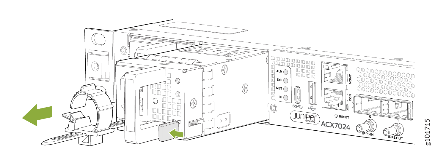
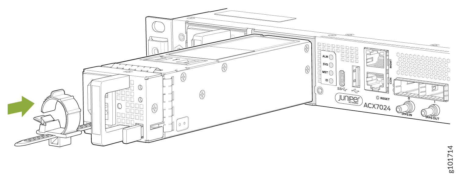
To remove an AC PSM from an ACX7024 or ACX7024X router (see Figure 1):
Install an ACX7024 or ACX7024X AC Power Supply Module
Before you install a PSM in a router, ensure that you have taken the necessary precautions to prevent electrostatic discharge (ESD) damage (see Prevention of Electrostatic Discharge Damage).
The power supply modules (PSMs) in ACX7024 and ACX7024X routers are hot-removable and hot-insertable field-replaceable units (FRUs). You can remove and replace the PSMs without powering off the router or disrupting routing functions.
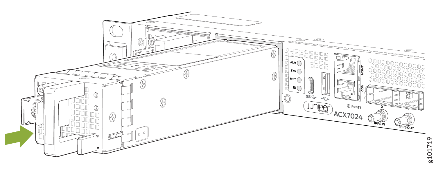
To install an AC PSM in an ACX7024 or ACX7024X router (see Figure 2):
- Wrap and fasten one end of the ESD grounding strap around your bare wrist, and connect the other end of the strap to the ESD point on the chassis.
- Taking care not to touch power supply components, pins, leads, or solder connections, remove the PSM from its bag.
- Using both hands, place the PSM in the power supply slot on the front panel of the router and slide it in until it is fully seated and the ejector lever slides into place.
- Press the latch located on the side of the PSM to slide it into the chassis.
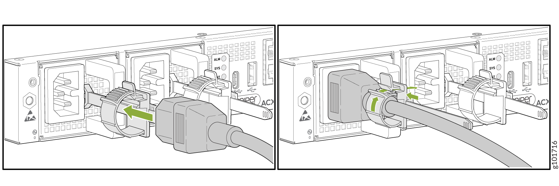
- Attach the power cord to the PSM.
- Attach the power cord to the AC power source, and switch on the dedicated customer-site 2-pole circuit breaker. Follow the instructions for your site.
- Observe the status LED on the power supply faceplate. If the PSM is correctly installed and functioning normally, the status LED lights green steadily.
Each PSM must be connected to a dedicated power source outlet.
Remove an ACX7024 or ACX7024X DC Power Supply Module
Before you remove a power supply module (PSM), be aware of the following:
The minimum required number of PSMs must always be present in the router.
Before performing DC power procedures, ensure that power is removed from the DC circuit. To ensure that all power is off, locate the two-pole circuit breaker on the panel board that services the DC circuit, switch the circuit breaker to the off position, and tape the switch handle of the circuit breaker in the off position.
After powering off a PSM, wait at least 60 seconds before turning it back on.
To remove a DC PSM:
- Switch off the dedicated customer-site two-pole circuit breaker for the PSM being removed. Follow your site's procedures for preventing ESD damage.
- Make sure that the voltage across the DC power source cable leads is 0 V and that there is no chance that the cables might become active during the removal process.
- Verify that the PWR LED on the PSM is unlit.
- Wrap and fasten one end of the ESD grounding strap around your bare wrist, and connect the other end of the strap to the ESD point on the chassis.
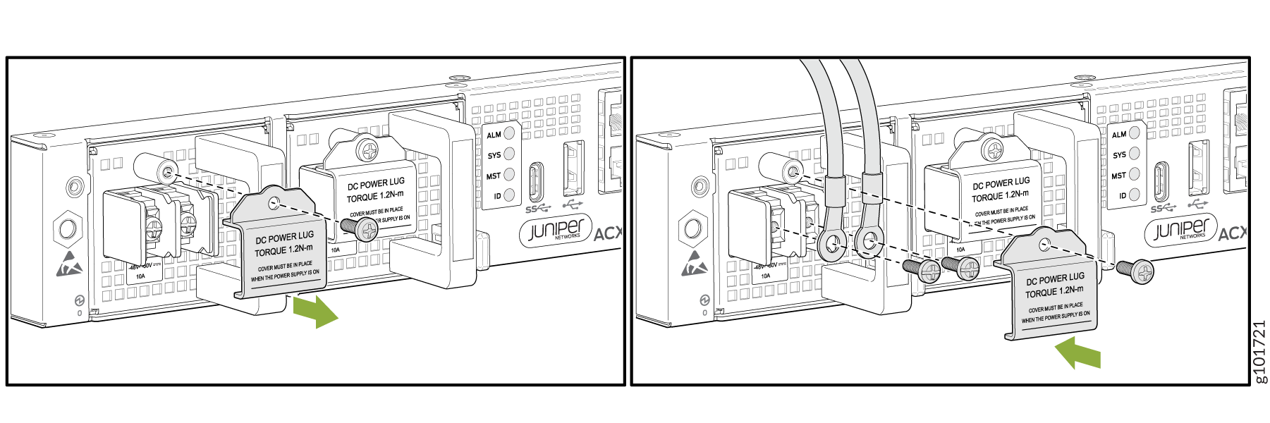
- Remove the terminal block cover protecting the terminals on the faceplate.
- Using a Phillips number 2 screwdriver, remove the screw from each of the DC power terminals (see Figure 4).
- Remove the cable lugs from the terminals.
- Carefully move the power cables out of the way.
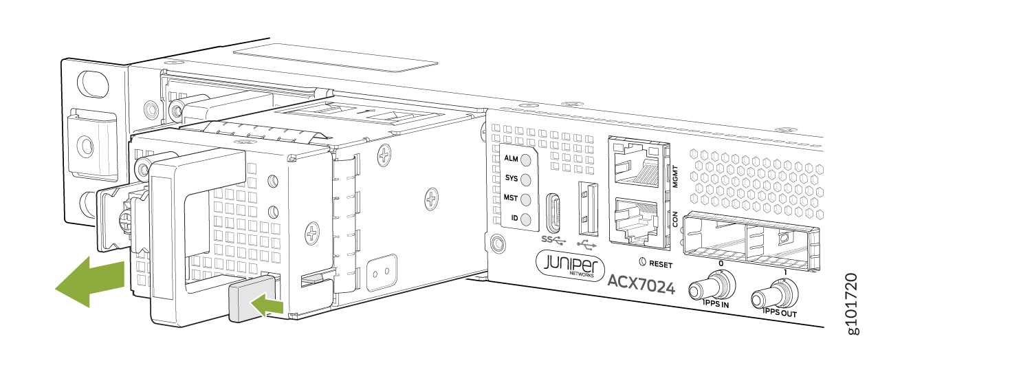
- Press the latch located on the DC PSM, to release it from the chassis.
- Pull the PSM straight out of the chassis (see Figure 5).
Install an ACX7024 or ACX7024X DC Power Supply Module
Before performing DC power procedures, ensure that power is removed from the DC circuit. To ensure that all power is off, locate the circuit breaker on the panel board that services the DC circuit, switch the circuit breaker to the off position, and tape the switch handle of the circuit breaker in the off position.
To install a DC PSM (see Figure 6):