Maintaining ACX5448, ACX5448-D, and ACX5448-M Components
Replace an ACX5400 Fan Module
Remove a Fan Module from an ACX5400 Router
Before you remove a fan module from an ACX5400 router, ensure that you have taken the necessary precautions to prevent electrostatic discharge (ESD) damage (see Prevention of Electrostatic Discharge Damage).
Ensure that you have the following parts and tools available to remove a fan module from an ACX5400 router:
-
ESD grounding strap
-
Antistatic bag or an antistatic mat
-
Phillips (+) screwdriver, number 2
The fan modules in ACX5400 routers are hot-removable and hot-insertable field replaceable units (FRUs): you can remove and replace them without powering off the router or disrupting routing functions.
Replace a failed fan module with a new fan module within 1 minute of removal to prevent chassis overheating. Before removing the fan module, ensure that you have a replacement fan module at hand.
To remove a fan module from an ACX5400 router (see Figure 1):
When you remove a fan module, the CLI message Fan/Blower is Absent is logged in the system log, and Junos OS raises a minor alarm.
Install a Fan Module in an ACX5400 Router
Before you install a fan module in an ACX5400 router, ensure that you have taken the necessary precautions to prevent electrostatic discharge (ESD) damage (see Prevention of Electrostatic Discharge Damage).
The fan modules in an ACX5400 router are hot-removable and hot-insertable field replaceable units (FRUs): you can remove and replace them without powering off the router or disrupting routing functions.
Replace a failed fan module with a new fan module within 1 minute of removal to prevent chassis overheating. Before removing the fan module, ensure that you have a replacement fan module at hand.
The fan module provides port-to-FRU airflow (AFO) or FRU-to-port (AFI) airflow depending on the product model that you purchase.
Ensure that you have the following parts and tools available to install a fan module in an ACX5400 router:
-
ESD grounding strap
-
Antistatic bag or an antistatic mat
-
Phillips (+) screwdriver, number 2
To install a fan module in an ACX5400 router (see Figure 2):
Replace an ACX5400 AC Power Supply Module
- Remove an AC Power Supply Module from an ACX5400 Router
- Install an AC Power Supply Module in an ACX5400 Router
Remove an AC Power Supply Module from an ACX5400 Router
Before you remove a PSM from a router, ensure that you have taken the necessary precautions to prevent electrostatic discharge (ESD) damage (see Prevention of Electrostatic Discharge Damage).
Ensure that you have the following parts and tools available to remove a PSM from a router:
-
ESD grounding strap
-
Antistatic bag or an antistatic mat
-
Phillips (+) screwdriver, number 2
The power supply modules (PSMs) in an ACX5400 router are hot-removable and hot-insertable field-replaceable units (FRUs): you can remove and replace them without powering off the router or disrupting routing functions.
Replace the PSM with a new PSM within 1 minute of removal to prevent chassis overheating.
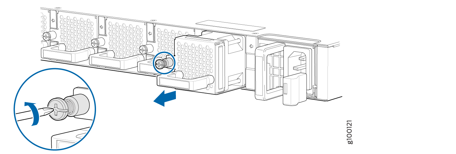
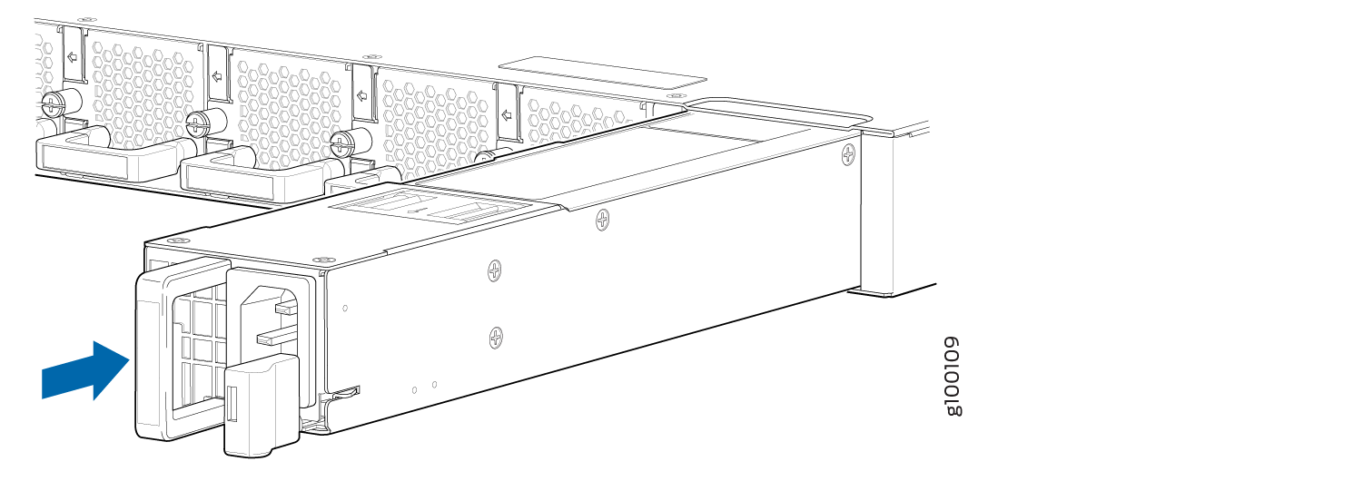
To remove an AC PSM from an ACX5400 router (see Figure 4):
Install an AC Power Supply Module in an ACX5400 Router
-
Before you install a PSM in a router, ensure that you have taken the necessary precautions to prevent electrostatic discharge (ESD) damage (see Prevention of Electrostatic Discharge Damage).
-
Ensure that the airflow direction of the PSM is the same as that indicated on the chassis. Labels on the PSM handle indicate the direction of airflow. See Cooling System and Airflow in ACX5448, ACX5448-D, and ACX5448-M Routers for more information.
The power supply modules (PSMs) in an ACX5400 router are hot-removable and hot-insertable field-replaceable units (FRUs): you can remove and replace them without powering off the router or disrupting routing functions.
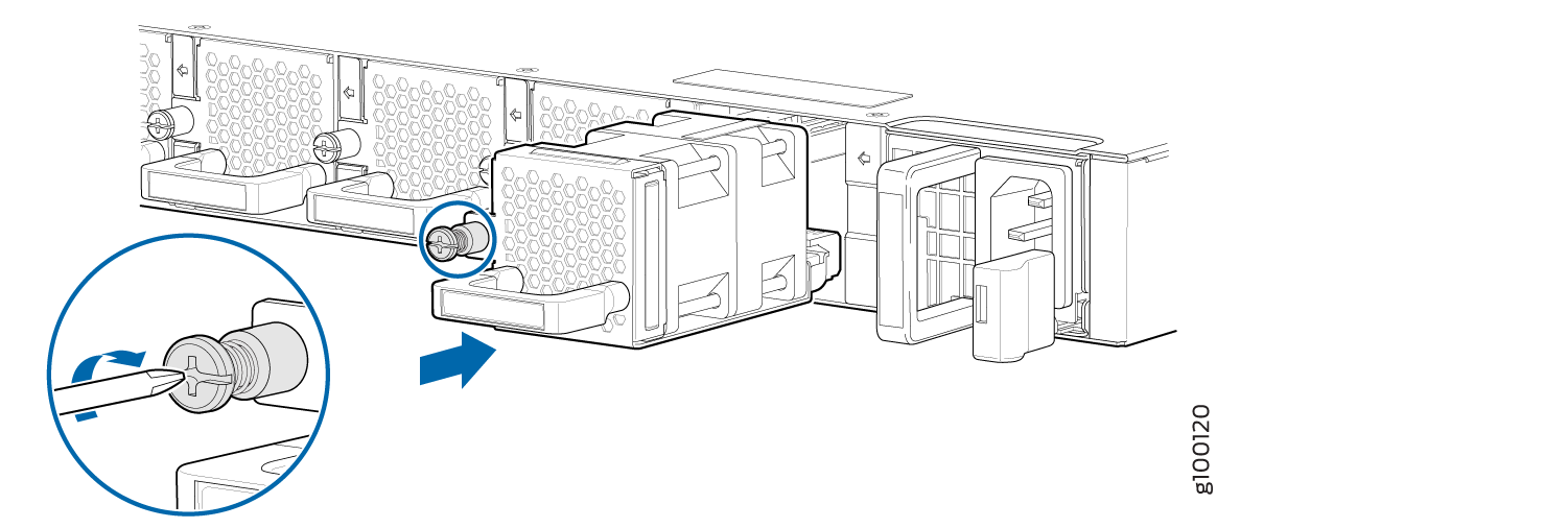
To install an AC PSM in an ACX5400 router (see Figure 5):
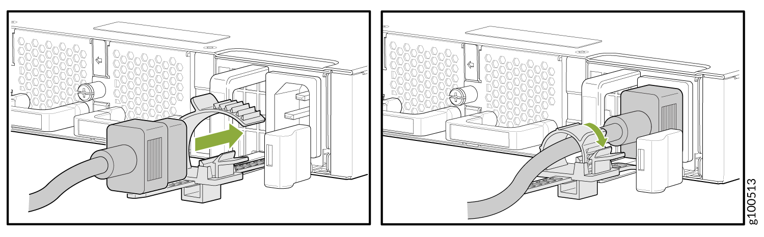
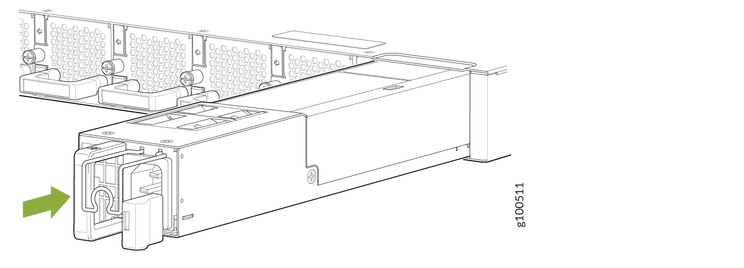
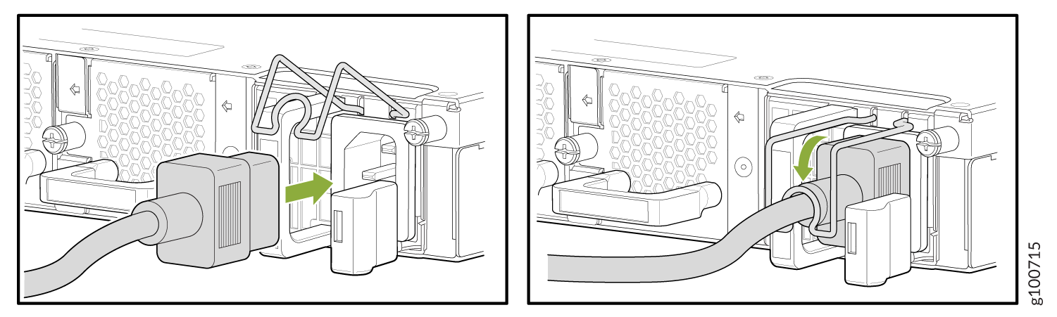
Each PSM must be connected to a dedicated power source outlet.
Replace an ACX5400 DC Power Supply Module
Remove an ACX5400 DC Power Supply Module
Before you remove a power supply module (PSM), be aware of the following:
The minimum required number of PSMs must be present in the router at all times.
Before performing DC power procedures, ensure that power is removed from the DC circuit. To ensure that all power is off, locate the 2-pole circuit breaker on the panel board that services the DC circuit, switch the circuit breaker to the off position, and tape the switch handle of the circuit breaker in the off position.
To maintain proper cooling and prevent thermal shutdown of the operating power supply unit, each power supply slot must contain a PSM. If you remove a PSM, you must install a replacement PSM shortly after the removal.
After powering off a PSM, wait at least 60 seconds before turning it back on.
Do not mix AC and DC PSMs in the same chassis.
To remove a DC PSM:
- Switch off the dedicated customer-site 2-pole circuit breaker for the PSM being removed. Follow your site's procedures for preventing ESD damage.
- Make sure that the voltage across the DC power source cable leads is 0 V and that there is no chance that the cables might become active during the removal process.
- Verify that the status LED on the PSM is not lit.
- Wrap and fasten one end of the ESD grounding strap around your bare wrist, and connect the other end of the strap to the ESD point on the chassis.
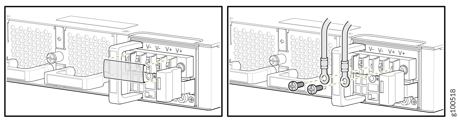
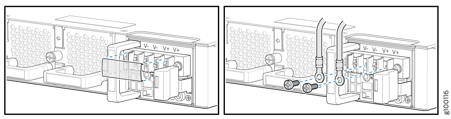
- Remove the clear plastic cover protecting the terminal studs on the faceplate.
- Using a socket screw driver, remove the screw from each of the DC power terminals (see Figure 9).
- Remove the cable lugs from the terminals.
- Carefully move the power cables out of the way.
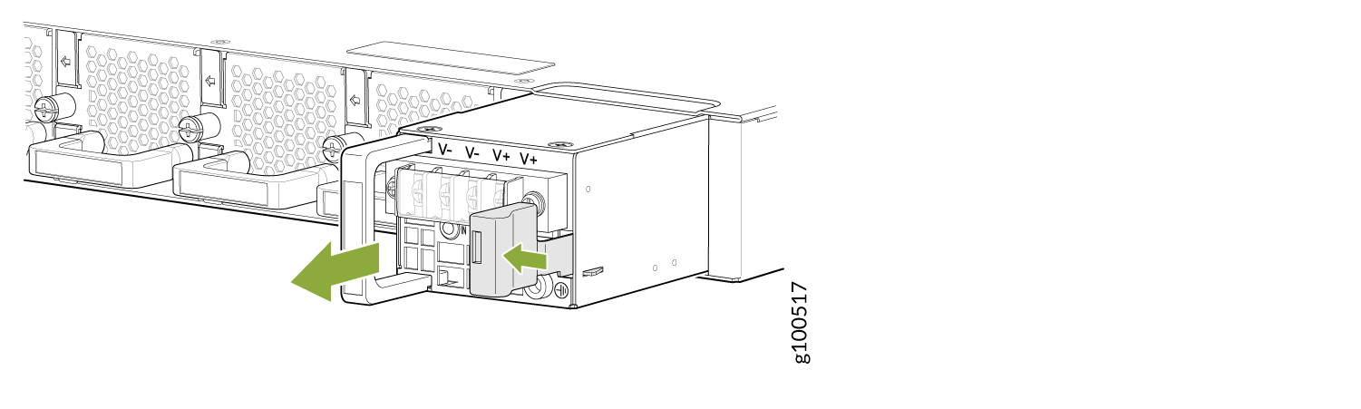
- Press the latch located on the DC PSM, to release it from the chassis.
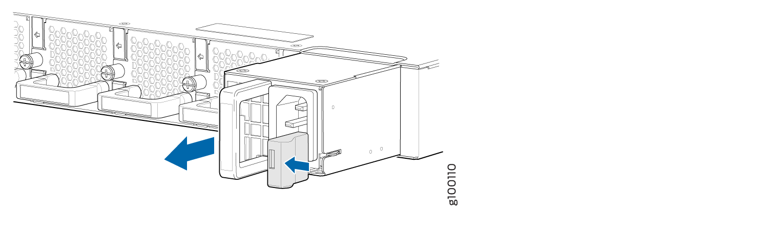
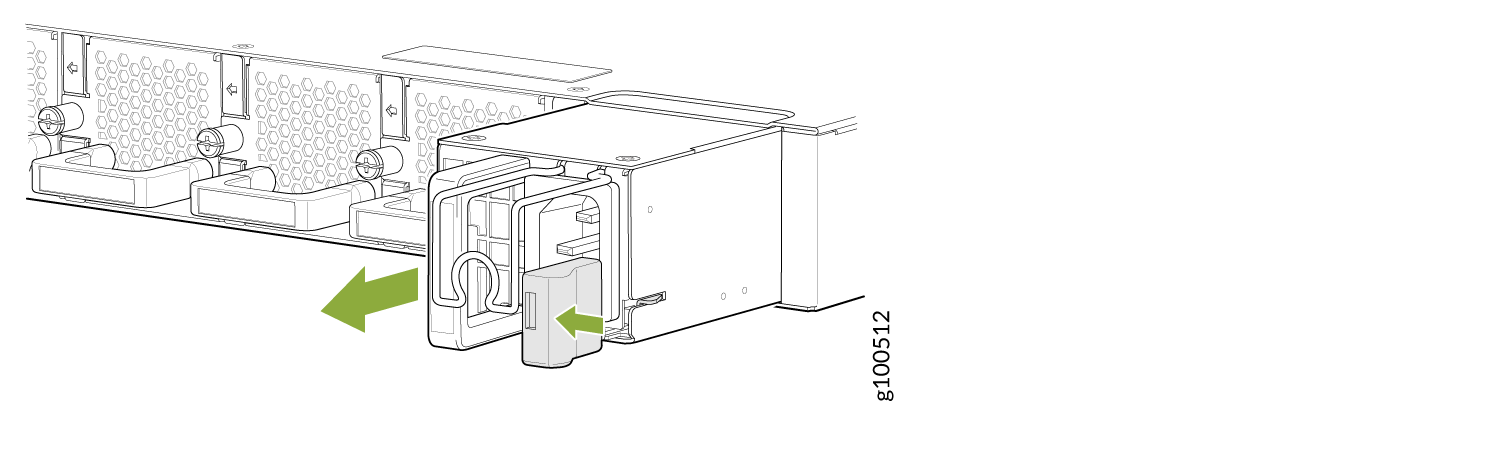
- Pull the PSM straight out of the chassis (see Figure 10).
Install an ACX5400 DC Power Supply Module
Before you perform DC power procedures, ensure there is no power to the DC circuit. To ensure that all power is off, locate the circuit breaker on the panel board that services the DC circuit, switch the circuit breaker to the off position, and tape the switch handle of the circuit breaker in the off position.
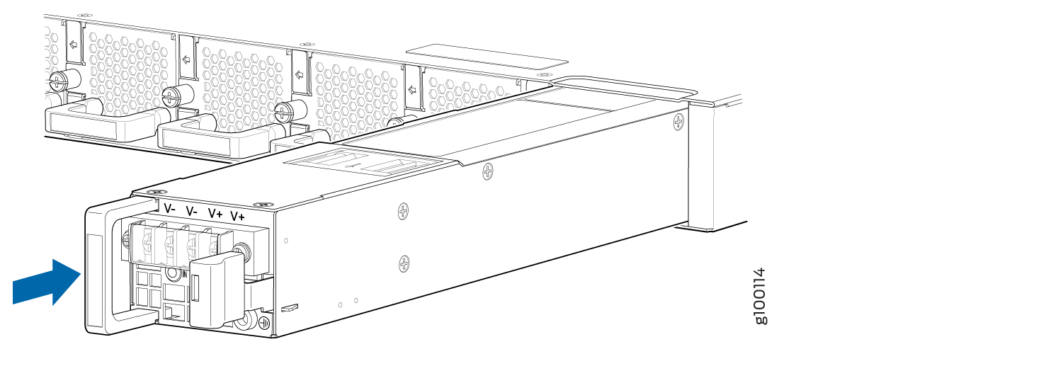
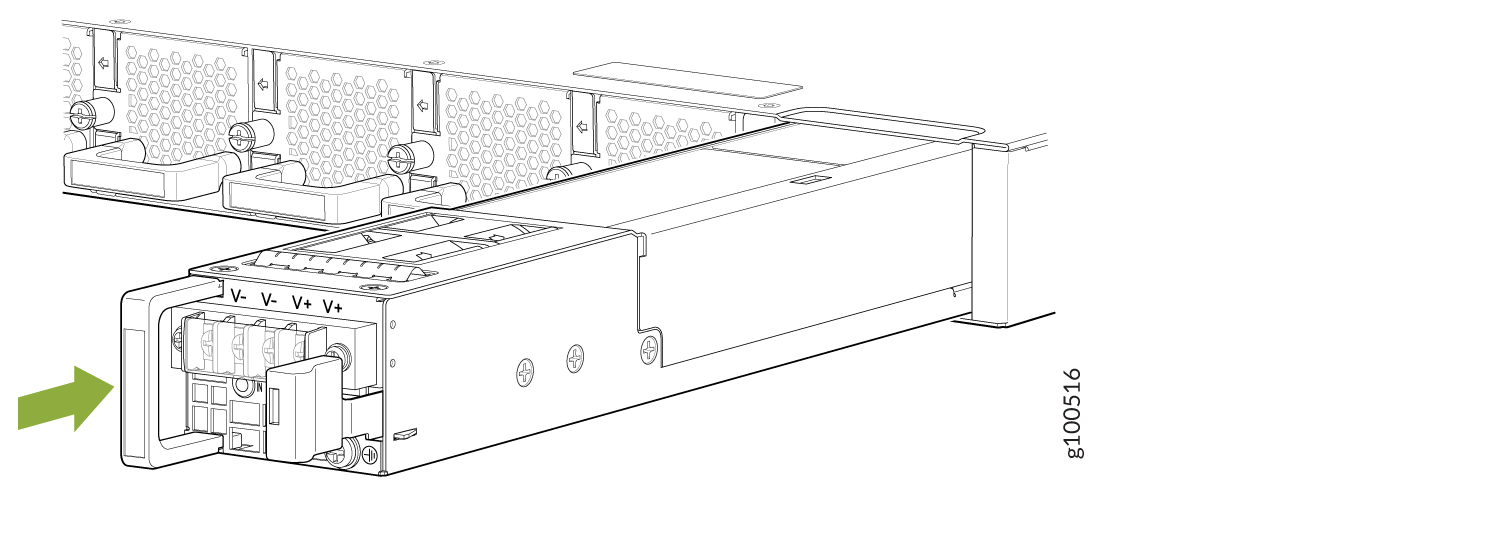
To install a DC PSM (see Figure 11):
Replace an SFP, SFP+, or QSFP+ Transceiver
The transceivers for Juniper Networks devices are hot-removable and hot-insertable field-replaceable units (FRUs). You can remove and replace them without powering off the device or disrupting the device functions.
Remove a Transceiver
Before you begin removing a transceiver from a device, ensure that you have taken the necessary precautions for the safe handling of lasers (see Laser and LED Safety Guidelines and Warnings).
Ensure that you have the following parts and tools available:
An antistatic bag or an antistatic mat
Rubber safety caps to cover the transceiver and fiber-optic cable connector
A dust cover to cover the port or a replacement transceiver
After you remove a transceiver or when you change the media-type configuration, wait for 6 seconds for the interface to display the operational commands.
To remove a transceiver:
- By using your fingers, pull open the ejector lever on
the transceiver to unlock the transceiver.CAUTION:
Ensure that you open the ejector handle completely until you hear it click. Doing this prevents damage to the transceiver.
Figure 14 shows how to remove an SFP transceiver. The procedure is the same for SFP+ and QSFP+ transceivers.
Figure 14: Small Form-Factor Pluggable (SFP) Transceiver
After removing a transceiver from the chassis, wait at least 30 seconds before reinserting it or inserting a transceiver into a different slot.
Install a Transceiver
Before you begin to install a transceiver in a device, ensure that you have taken the necessary precautions for safe handling of lasers (see Laser and LED Safety Guidelines and Warnings).
Ensure that you have a rubber safety cap available to cover the transceiver.
After you insert a transceiver or after you change the media-type configuration, wait for 6 seconds for the interface to display operational commands.
We recommend that you use only optical transceivers and optical connectors purchased from Juniper Networks with your Juniper Networks device.
The Juniper Networks Technical Assistance Center (JTAC) provides complete support for Juniper-supplied optical modules and cables. However, JTAC does not provide support for third-party optical modules and cables that are not qualified or supplied by Juniper Networks. If you face a problem running a Juniper device that uses third-party optical modules or cables, JTAC may help you diagnose host-related issues if the observed issue is not, in the opinion of JTAC, related to the use of the third-party optical modules or cables. Your JTAC engineer will likely request that you check the third-party optical module or cable and, if required, replace it with an equivalent Juniper-qualified component.
Use of third-party optical modules with high-power consumption (for example, coherent ZR or ZR+) can potentially cause thermal damage to or reduce the lifespan of the host equipment. Any damage to the host equipment due to the use of third-party optical modules or cables is the users’ responsibility. Juniper Networks will accept no liability for any damage caused due to such use.
To install a transceiver:
- Slide in the transceiver until it is fully seated. If
you are unable to fully insert the transceiver, ensure that the connector
is facing the right way.Figure 15: Install a Transceiver
 1—
1—Ejector lever
Replace a QSFP28 Transceiver
28-Gbps quad small form-factor pluggable (QSFP28) transceivers are hot-insertable and hot-removable. Removing a QSFP28 transceiver does not interrupt router functioning, but the removed QSFP28 transceiver no longer receives or transmits data.
Remove a QSFP28 Transceiver
Before you begin to remove a transceiver from a device, ensure that you have taken the necessary precautions for safe handling of lasers (see Laser and LED Safety Guidelines and Warnings).
Ensure that you have the following parts and tools available:
An antistatic bag or an antistatic mat
Rubber safety caps to cover the transceiver and fiber-optic cable connector
A dust cover to cover the port or a replacement transceiver
The transceivers for Juniper Networks devices are hot-removable and hot-insertable field-replaceable units (FRUs). You can remove and replace them without powering off the device or disrupting the device functions.
After you insert a transceiver or after you change the media-type configuration, wait for 6 seconds for the interface to display operational commands.
We recommend that you use only optical transceivers and optical connectors purchased from Juniper Networks with your Juniper Networks device.
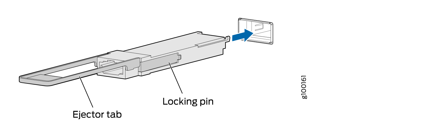
To remove a QSFP28 transceiver (see Figure 16):
- Pull the transceiver’s rubber handle straight back.
The locking pins on the transceiver automatically releases the transceiver.
Figure 16: 28-Gbps Quad Small Form-Factor Pluggable (QSFP28) Transceiver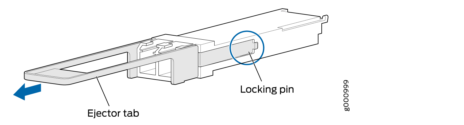
Install a QSFP28 Transceiver
Before you begin to install a transceiver in a device, ensure that you have taken the necessary precautions for safe handling of lasers (see Laser and LED Safety Guidelines and Warnings).
Ensure that you have a rubber safety cap available to cover the transceiver.
The transceivers for Juniper Networks devices are hot-removable and hot-insertable field-replaceable units (FRUs): You can remove and replace them without powering off the device or disrupting the device functions.
After you insert a transceiver or after you change the media-type configuration, wait for 6 seconds for the interface to display operational commands.
We recommend that you use only optical transceivers and optical connectors purchased from Juniper Networks with your Juniper Networks device.
The Juniper Networks Technical Assistance Center (JTAC) provides complete support for Juniper-supplied optical modules and cables. However, JTAC does not provide support for third-party optical modules and cables that are not qualified or supplied by Juniper Networks. If you face a problem running a Juniper device that uses third-party optical modules or cables, JTAC may help you diagnose host-related issues if the observed issue is not, in the opinion of JTAC, related to the use of the third-party optical modules or cables. Your JTAC engineer will likely request that you check the third-party optical module or cable and, if required, replace it with an equivalent Juniper-qualified component.
Use of third-party optical modules with high-power consumption (for example, coherent ZR or ZR+) can potentially cause thermal damage to or reduce the lifespan of the host equipment. Any damage to the host equipment due to the use of third-party optical modules or cables is the users’ responsibility. Juniper Networks will accept no liability for any damage caused due to such use.
To install a replacement QSFP28 transceiver (see Figure 17):
- Orient the transceiver in front of the port so that the
QSFP28 connector faces the appropriate direction.Figure 17: Install a QSFP28 Transceiver
Replacing a CFP2 Transceiver
Removing a CFP2 Transceiver
CFP2 transceivers are hot-insertable and hot-removable. Removing a CFP2 transceiver does not interrupt the device functions, but the removed CFP2 transceiver no longer receives or transmits data.
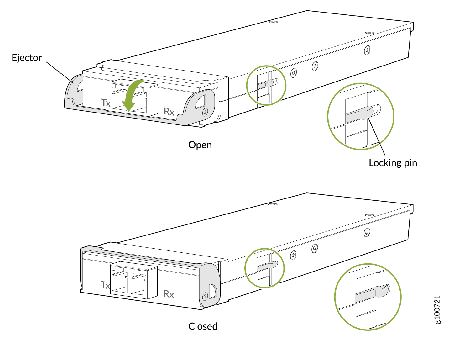
To remove a CFP2 transceiver (see Figure 18):
Installing a CFP2 Transceiver
To install a replacement CFP2:
How to Handle Fiber-Optic Cables
Fiber-optic cables connect to optical transceivers that are installed in Juniper Networks devices.
Follow these guidelines when handling fiber-optic cables:
When you unplug a fiber-optic cable from a transceiver, place rubber safety caps over the transceiver and on the end of the cable.
Anchor fiber-optic cables to prevent stress on the connectors. When attaching a fiber-optic cable to a transceiver, secure the fiber-optic cable so that it does not support its own weight as it hangs to the floor. Never let a fiber-optic cable hang free from the connector.
Avoid bending the fiber-optic cables beyond their minimum bend radius. Bending fiber-optic cables into arcs smaller than a few inches in diameter can damage the cables and cause problems that are difficult to diagnose.
Frequent plugging and unplugging of fiber-optic cables in and out of optical instruments can damage the instruments, which are expensive to repair. To prevent damage from overuse, attach a short fiber extension to the optical equipment. The short fiber extension absorbs wear and tear due to frequent plugging and unplugging. It is easier and more cost-efficient to replace the short fiber extension than to replace the instruments.
Keep fiber-optic cable connections clean. Microdeposits of oil and dust in the canal of the transceiver or cable connector can cause loss of light, reduction in signal power, and possibly intermittent problems with the optical connection.
To clean the transceiver canal, use an appropriate fiber-cleaning device such as RIFOCS Fiber Optic Adaptor Cleaning Wands (part number 946). Follow the instructions in the cleaning kit you use.
After cleaning the transceiver, make sure that the connector tip of the fiber-optic cable is clean. Use only an approved alcohol-free fiber-optic cable cleaning kit such as the Opptex Cletop-S® Fiber Cleaner. Follow the instructions in the cleaning kit you use.