Unpack and Mount the QFX5120 Switch
Unpack the QFX5120 Switch
We ship QFX5120 switches in a cardboard carton, secured with foam packing material.
QFX5120 switches are maximally protected inside the shipping carton. Do not unpack the switches until you are ready to mount the switch.
To unpack the switch:
- Move the shipping carton to a staging area as close to the installation site as possible, but where you have enough room to remove the system components.
- Position the carton so that the arrows marked on the carton are pointing up.
- Open the top flaps on the shipping carton.
- Pull out the packing material holding the switch in place.
- Verify the parts received against the inventory on the label attached to the carton.
- Save the shipping carton and packing materials in case you need to move or ship the switch later.
Parts Inventory (Packing List) for a QFX5120 Switch
The switch shipment includes a packing list. Check the parts you receive with the switch against the items in the packing list. The packing list specifies the part number and provides a description of each part in your order. The parts shipped depend on the switch model you order.
If any part in the packing list is missing, contact your customer service representative or contact Juniper customer care from within the U.S. or Canada by telephone at 1-888-314-5822. For international-dial or direct-dial options in countries without toll-free numbers, see https://www.juniper.net/support/requesting-support.html .
Table 1 lists the parts and their quantities as in the standard packing list for a QFX5120 switch.
|
Component |
Quantity |
|
|---|---|---|
|
Switch |
1 |
|
|
Fan modules |
QFX5120-32C |
6 preinstalled |
|
QFX5120-48T, QFX5120-48Y, and QFX5120-48YM |
5 preinstalled |
|
|
Power supplies |
2 (AC or DC) preinstalled |
|
|
AC power cords appropriate for your geographical location for AC-powered models |
2 |
|
|
Four-post rack mount kit - QFX5120-48T, QFX5120-48Y, and QFX5120-48YM |
Rack mount kit - JNP-4PST-RMK-1U-E (Partial toolless RMK) JNP-4PST-RMK-1U-E rack mount kit consists of the following parts:
Spare rack mount kits order numbers
|
1 |
|
Four-post tool less rack mount kit - QFX5120-32C |
QFX5120-32C-RMK-E Rack mount kit - QFX5120-32C-RMK-E (Toolless RMK) QFX5120-32C-RMK-E rack mount kit consists of the following parts:
|
1 |
|
Documentation Roadmap |
1 |
|
|
End User License Agreement |
1 |
|
- RJ-45 to DB-9 adapter (JNP-CBL-RJ45-DB9)
- RJ-45 to USB-A adapter (JNP-CBL-RJ45-USBA)
- RJ-45 to USB-C adapter (JNP-CBL-RJ45-USBC)
If you want to use RJ-45 to USB-A or RJ-45 to USB-C adapter you must have X64 (64-Bit) Virtual COM port (VCP) driver installed on your PC. See, https://ftdichip.com/drivers/vcp-drivers/ to download the driver.
You must provide the appropriate mounting screws for mounting the switch on a rack or a cabinet.
All the rack mount kits are separately orderable.
| Model | Rack Mount Kit |
|---|---|
|
QFX5120-32C |
|
|
QFX5120-48YM |
|
|
QFX5120-48T |
|
| QFX5120-48Y |
|
Update Base Installation Data
Update the installation base data if any addition or change to the installation base occurs or if the installation base is moved. Juniper Networks is not responsible for not meeting the hardware replacement SLA for products that do not have accurate installation base data.
Update your installation base at https://supportportal.juniper.net/s/CreateCase .
Mount a QFX5120-32C Switch on a Four-Post Rack
Before mounting a QFX5120-32C switch:
-
Verify that the site meets the requirements described in Site Preparation Checklist for QFX5120 Switches.
-
Place the rack in its permanent location, allowing adequate clearance for airflow and maintenance, and secure the rack to the building structure.
-
Read General Safety Guidelines and Warnings, with particular attention to Chassis and Component Lifting Guidelines.
-
Ensure that you have taken the necessary precautions to prevent electrostatic discharge (ESD) damage (see Prevention of Electrostatic Discharge Damage).
-
Remove the switch from the shipping carton (see Unpack the QFX5120 Switch).
Ensure that you have the following parts and tools available:
-
Number 2 Phillips (+) screwdriver—not provided
-
Eight screws to secure the mounting brackets to the rack—not provided
-
Electrostatic discharge (ESD) grounding strap—not provided
-
Front mounting brackets—2 (provided with the rack mount kit)
-
Side mounting rails—2 (provided with the rack mount kit)
-
Flat head M4X8 screws to attach the front mounting brackets and side mounting rails to the switch chassis—20 (provided with the rack mount kit)
-
Rear mounting (L-shaped) brackets—2 (provided with the rack mount kit)
-
Pan head M4X8 screws to attach the rear mounting brackets to the side mounting rails—2 (provided with the rack mount kit)
You can mount a QFX5120-32C switch on four posts of a 19-in. rack or in a cabinet that contains a four-post 19-in. rack by using a rack mount kit. (The remainder of this topic uses rack to mean rack or cabinet.)
One person must be available to lift the switch while another person secures the switch to the rack.
If you are mounting multiple units on a rack, mount the heaviest unit at the bottom of the rack, and then mount the other units from the bottom of the rack to the top in decreasing order of the weight of the units.
To mount a QFX5120-32C switch:
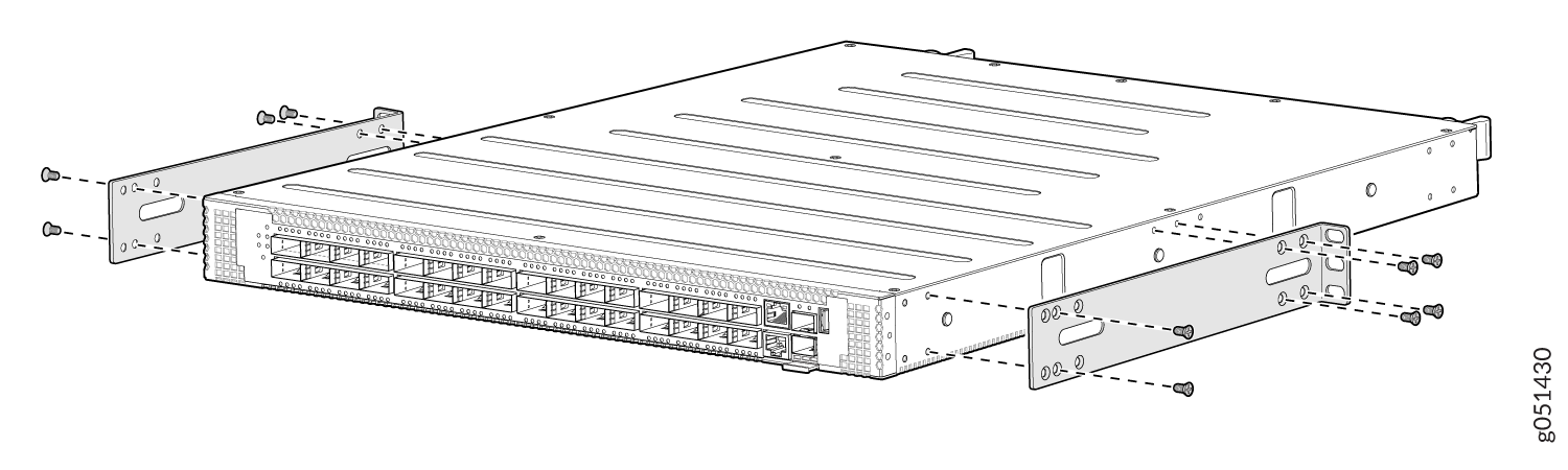
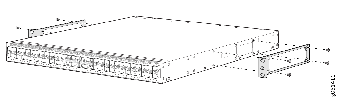
-
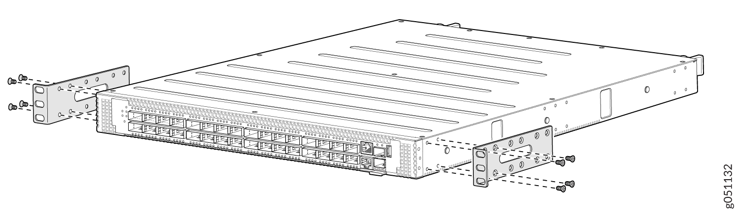
Align the front mounting brackets along the side panel of the switch such that
the front of the bracket is flush with the front panel of the switch chassis.
Insert the flat head M4X8 screws for attaching the front mounting brackets into
the aligned holes on the chassis and tighten the screws (see Figure 1).
Figure 1: Attach the Front Mounting Brackets to a QFX5120-32C Switch Chassis
-
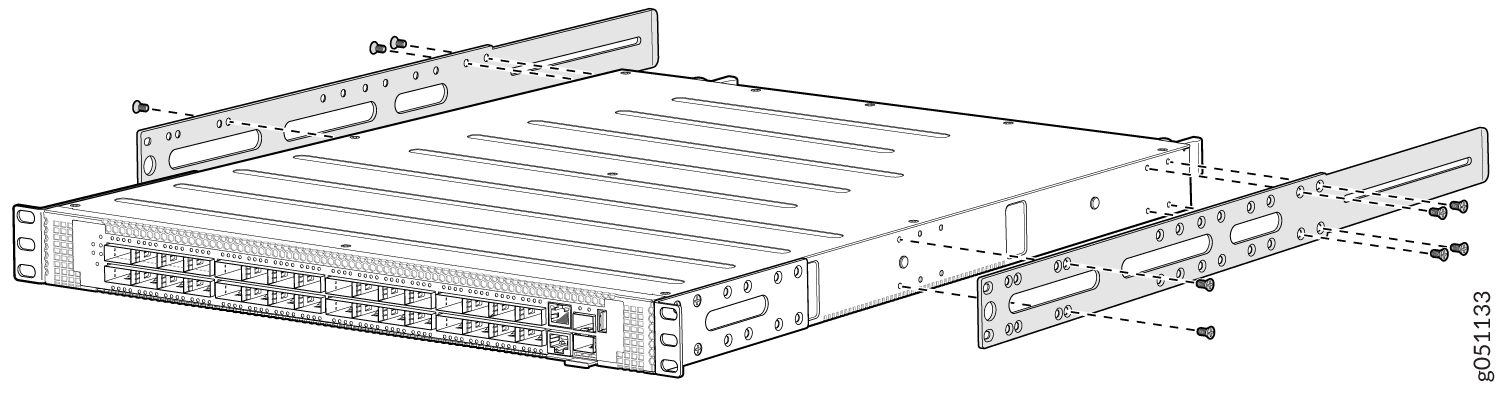
Align the side mounting rails along the side panel of the switch. Insert the
flat head M4X8 screws for attaching the side mounting rails into the aligned
holes on the chassis and tighten the screws (see Figure 2).
Figure 2: Attach the Side Mounting Rails to a QFX5120-32C Switch Chassis
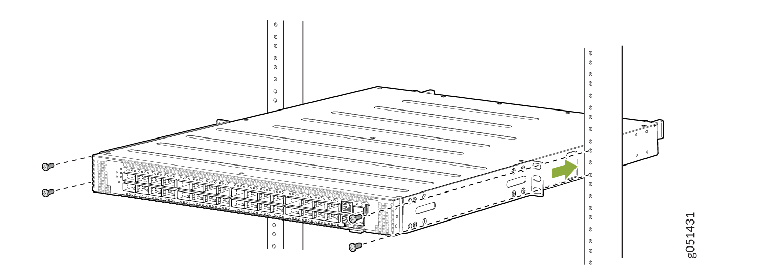
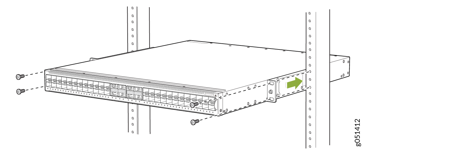
-
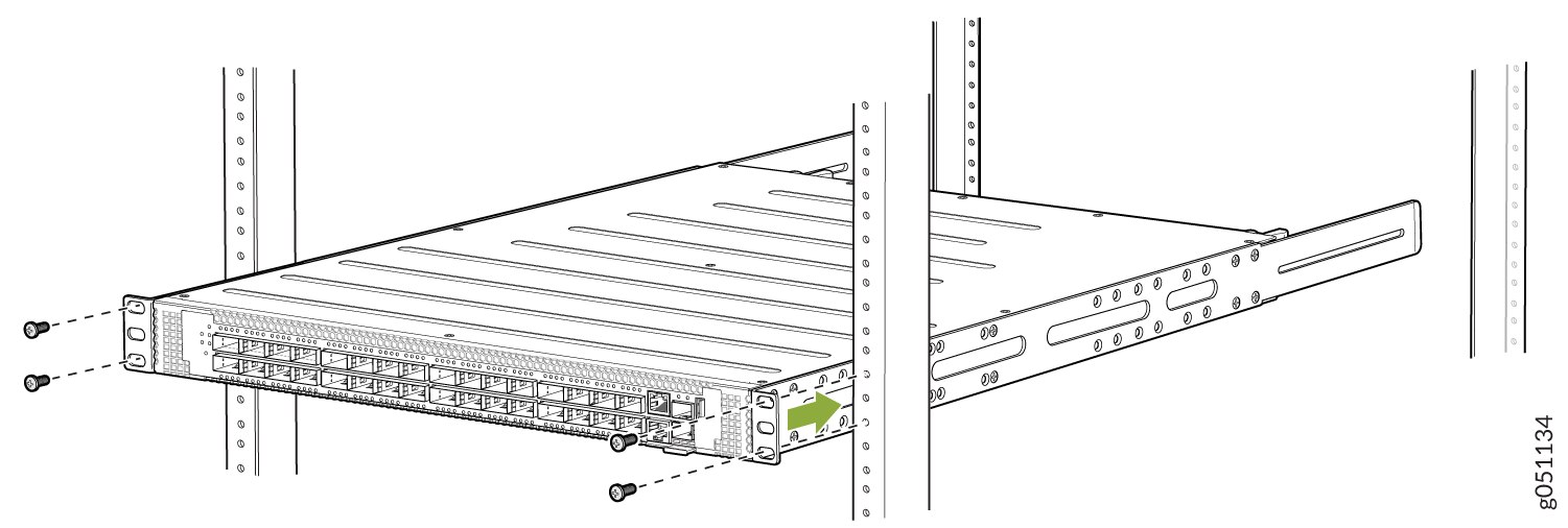
Have a second person secure the front of the switch to the rack by using the
screws appropriate for your rack. Tighten the screws (see Figure 3).
Figure 3: Secure the QFX5120-32C Switch to the Front Posts of a Rack
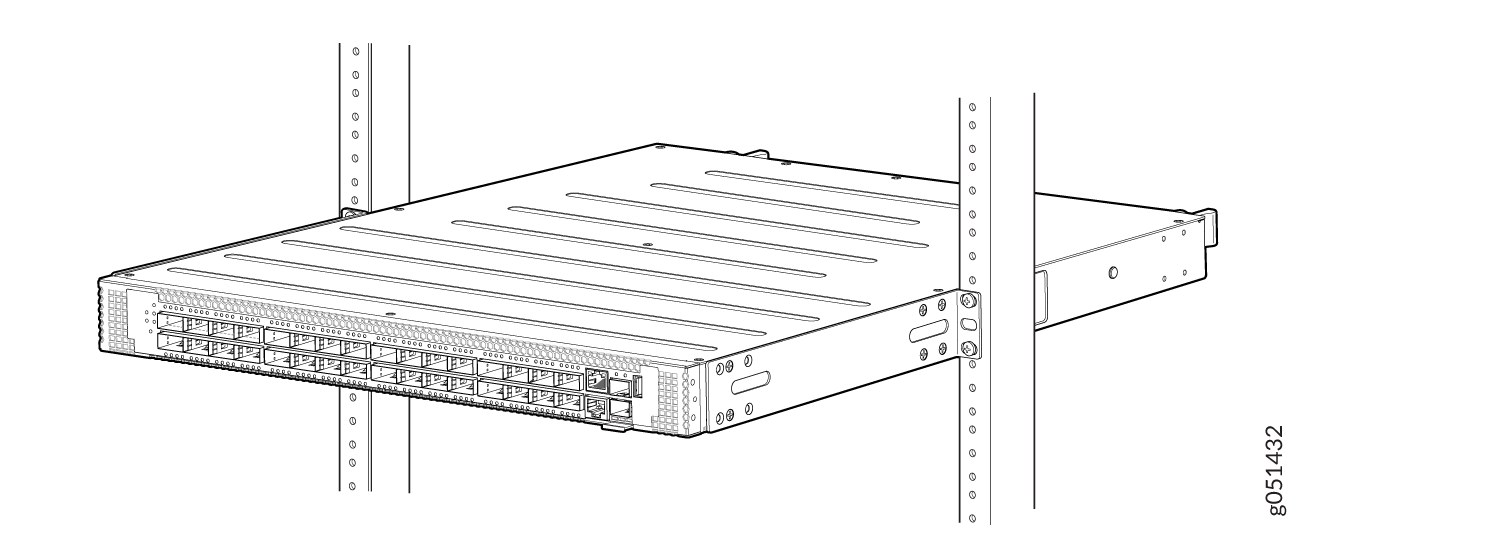
-
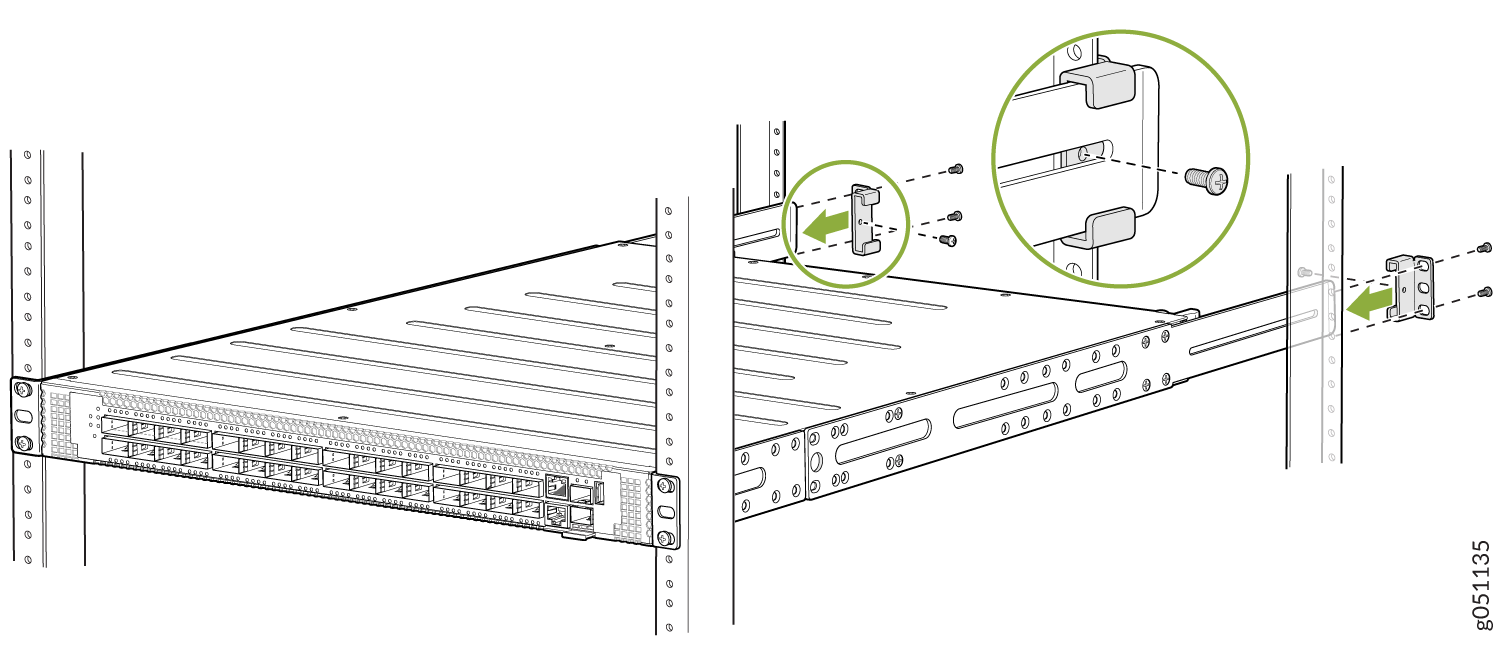
Secure the rear mounting brackets to the rear post of the rack by using screws
appropriate for your rack (see Figure 4). Tighten the screws.
Figure 4: Secure the QFX5120-32C Switch to the Rear Post of the Rack by Using the Rear Mounting Brackets
Mount a QFX5120-32C Switch on a Two-Post Rack
Before you mount a QFX5120-32C switch on a two-post rack:
-
Verify that the site meets the requirements described in Site Preparation Checklist for QFX5120 Switches.
-
Place the rack in its permanent location, allowing adequate clearance for airflow and maintenance, and secure the rack to the building structure.
-
Read General Safety Guidelines and Warnings, with particular attention to Chassis and Component Lifting Guidelines.
-
Ensure that you have taken the necessary precautions to prevent electrostatic discharge (ESD) damage (see Prevention of Electrostatic Discharge Damage).
-
Remove the switch from the shipping carton (see Unpack the QFX5120 Switch).
Ensure that you have the following parts and tools available:
-
Number 2 Phillips (+) screwdriver—not provided
-
Eight screws to secure the mounting brackets to the rack—not provided
-
Electrostatic discharge (ESD) grounding strap—not provided
-
Two-post rack mounting bracket for mounting the switch on a two-post rack—2 (provided with the two-post rack mount kit)
-
Flat head 4x6-mm Phillips screws for attaching the two-post rack mounting brackets to the chassis—8 (provided with the two-post rack mount kit)
You can mount a QFX5120 switch on four posts of a four-post 19-in. rack or in a cabinet that contains a four-post 19-in. rack, flush with the front posts, by using a four-post rack mount kit. (The remainder of this topic uses rack to mean rack or cabinet.) You can mount QFX5120-48T, QFX5120-48Y, and QFX5120-48YM switches in a recessed position inside a four-post rack by using the recessed mounting brackets. You can also mount QFX5120-48YM switches on a two-post rack by using a separately orderable two-post rack mount kit.
One person must be available to lift the switch while another person secures the switch to the rack.
If you are mounting multiple units on a rack, mount the heaviest unit at the bottom of the rack, and then mount the other units from the bottom of the rack to the top in decreasing order of the weight of the units.
To mount a QFX5120-32C switch on a two-post rack:
-
Insert the flat head 4x6-mm Phillips screws for attaching the two-post rack
mounting brackets (provided with the two-post rack mount kit) into the
aligned holes on the chassis. Tighten the screws (see Figure 5) .
Figure 5: Attach the Two-Post Mounting Brackets to a QFX5120-32C Switch
-
Have a second person secure the switch to the rack by using the screws
appropriate for your rack. Tighten the screws (see Figure 6).
Figure 6: Secure the QFX5120-32C Switch to the Two-Post Rack
-
Your switch is now installed on a two-post rack (see Install the QFX5120-32C Switch to the Two-Post
Rack.)
Figure 7: Mount the QFX5120-32C Switch to the Two-Post Rack
Mount a QFX5120-32C by Using the QFX5120-32C-RMK-E Rack Mount Kit
Use the information in this topic to install the QFX5120-32C by using the QFX5120-32C-RMK-E rack mount kit.
You can mount QFX5120-32 switches on a square hole or threaded hole four-post 19-in. racks using the tool less QFX5120-32C-RMK-E rack mount kit.
QFX5120-32C-RMK-E rack mount kit consists of the following parts:
-
A pair of side mounting brackets that attach to the chassis
-
A pair of front and rear mounting rails that attach to the rack posts
A four-post installation evenly supports the device by all four corners.
Before mounting a QFX5120-32C switch:
-
Verify that the site meets the requirements described in Site Preparation Checklist for QFX5120 Switches.
-
Place the rack in its permanent location, allowing adequate clearance for airflow and maintenance, and secure the rack to the building structure.
-
Read General Safety Guidelines and Warnings, with particular attention to Chassis and Component Lifting Guidelines.
-
Ensure that you have taken the necessary precautions to prevent electrostatic discharge (ESD) damage (see Prevention of Electrostatic Discharge Damage).
-
Remove the switch from the shipping carton (see Unpack the QFX5120 Switch).
- Mount a QFX5120-32C by Using the QFX5120-32C-RMK-E Rack Mount Kit on a Square Hole 4-Post Rack
- Mount a QFX5120-32C by Using the QFX5120-32C-RMK-E Rack Mount Kit on a Threaded-Hole 4-Post Rack
Mount a QFX5120-32C by Using the QFX5120-32C-RMK-E Rack Mount Kit on a Square Hole 4-Post Rack
Ensure that you have the following tools and parts available:
-
An ESD grounding strap—not provided.
-
QFX5120-32C-RMK-E Rack Mount Kit
To mount the device on a four-post rack:
-
To attach the side mounting brackets to the chassis, align the keyholes on the mounting
brackets over the shoulder screws on the chassis. Slide the mounting brackets toward the
rear of the chassis.
Figure 8: Attach the Side Mounting Brackets

-
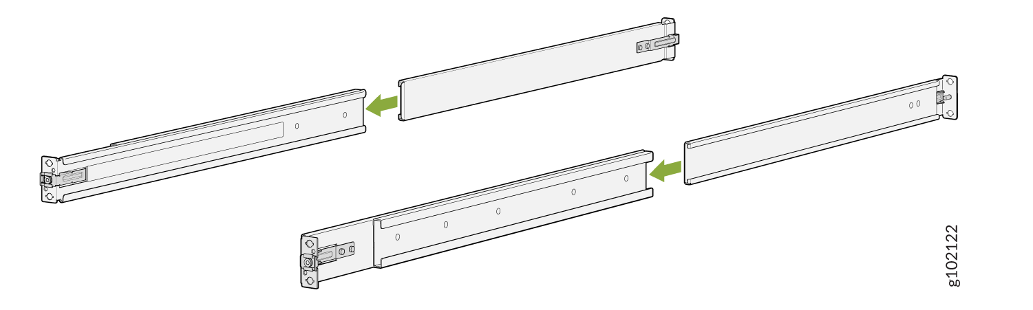
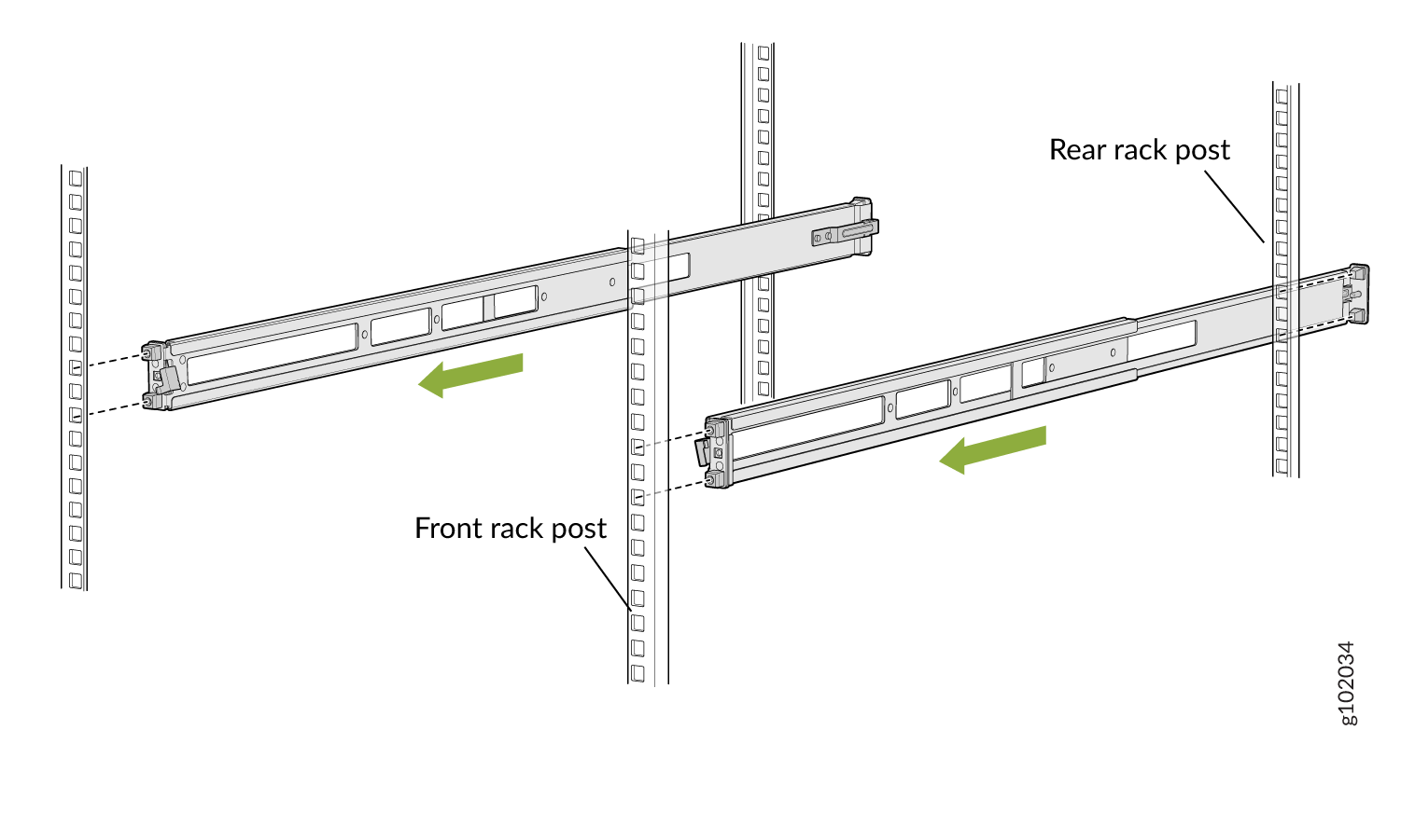
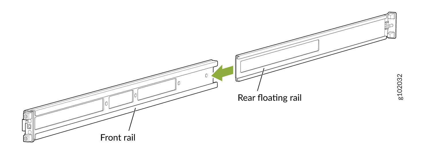
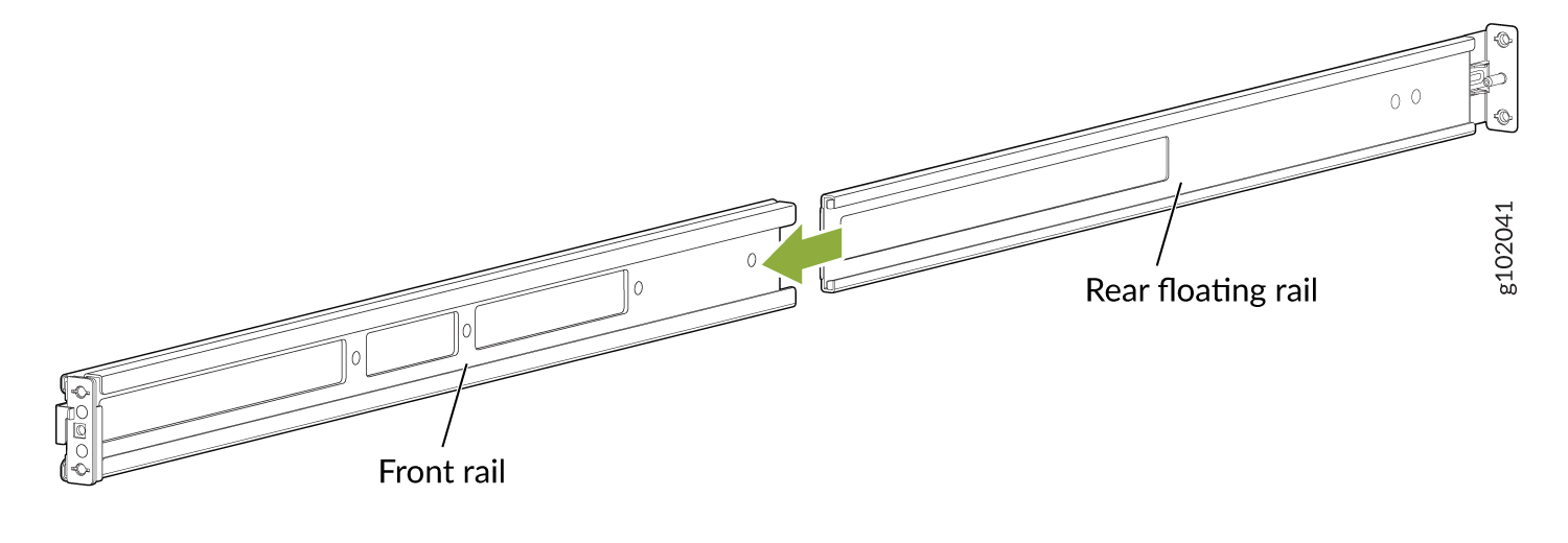
Assemble the mounting rails by sliding the rear floating rails into the front
rails.
Figure 9: Assemble the Mounting Rails

-
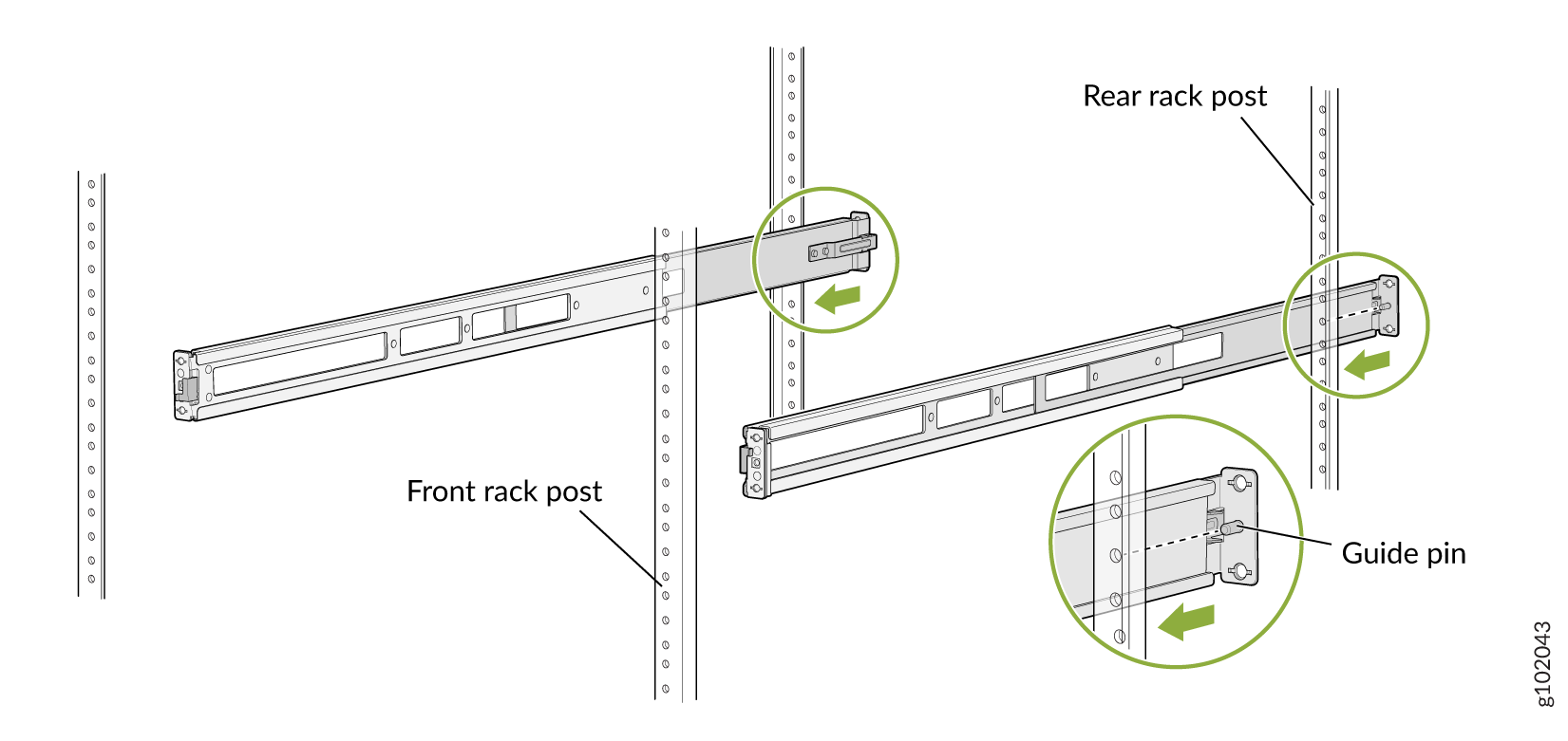
Install the mounting rails on the rack:
-
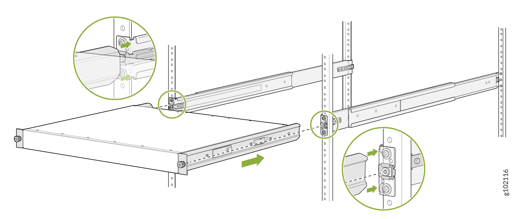
Align the guide blocks of the rear mounting rails with the rear-post holes. Pull
the rear mounting rails toward the front of the rack to lock the rails in place. You
will hear a distinct click sound when the latch locks into the corresponding rack
holes.
Figure 10: Install the Rear Mounting Rails
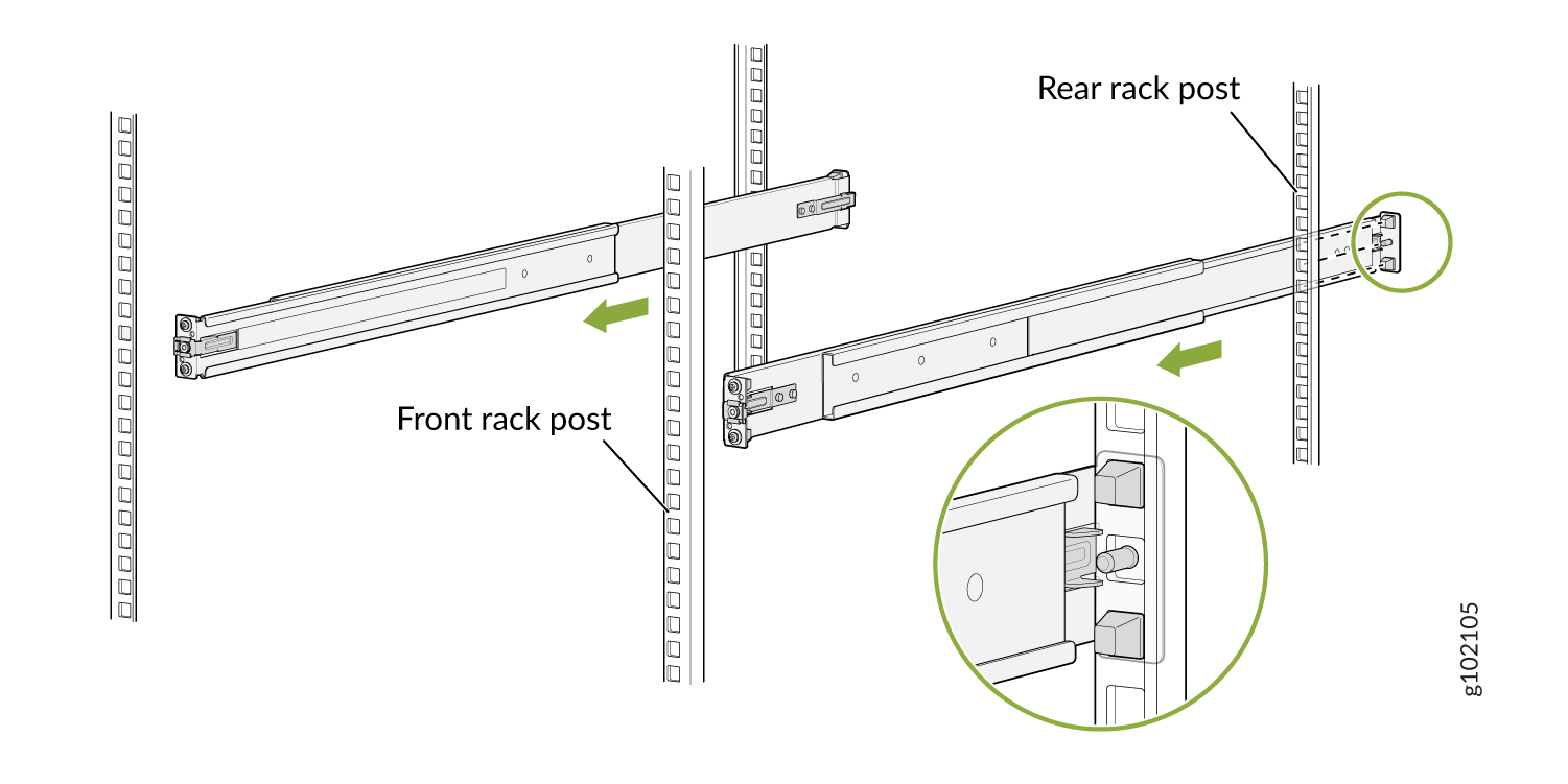
-
Align the guide blocks of the front mounting rails with the front-post holes. Push
the front mounting rails toward the rear of the rack to lock the rails in place. You
will hear a distinct click sound when the latch locks into the corresponding rack
holes.
Figure 11: Install the Front Mounting Rails

-
Align the guide blocks of the rear mounting rails with the rear-post holes. Pull
the rear mounting rails toward the front of the rack to lock the rails in place. You
will hear a distinct click sound when the latch locks into the corresponding rack
holes.
-
Lift the device and position it in the rack, aligning the side mounting-brackets with
the mounting rails. Slide the device into the channels of the rack mounting rails.
Figure 12: Slide the Device into the Rack
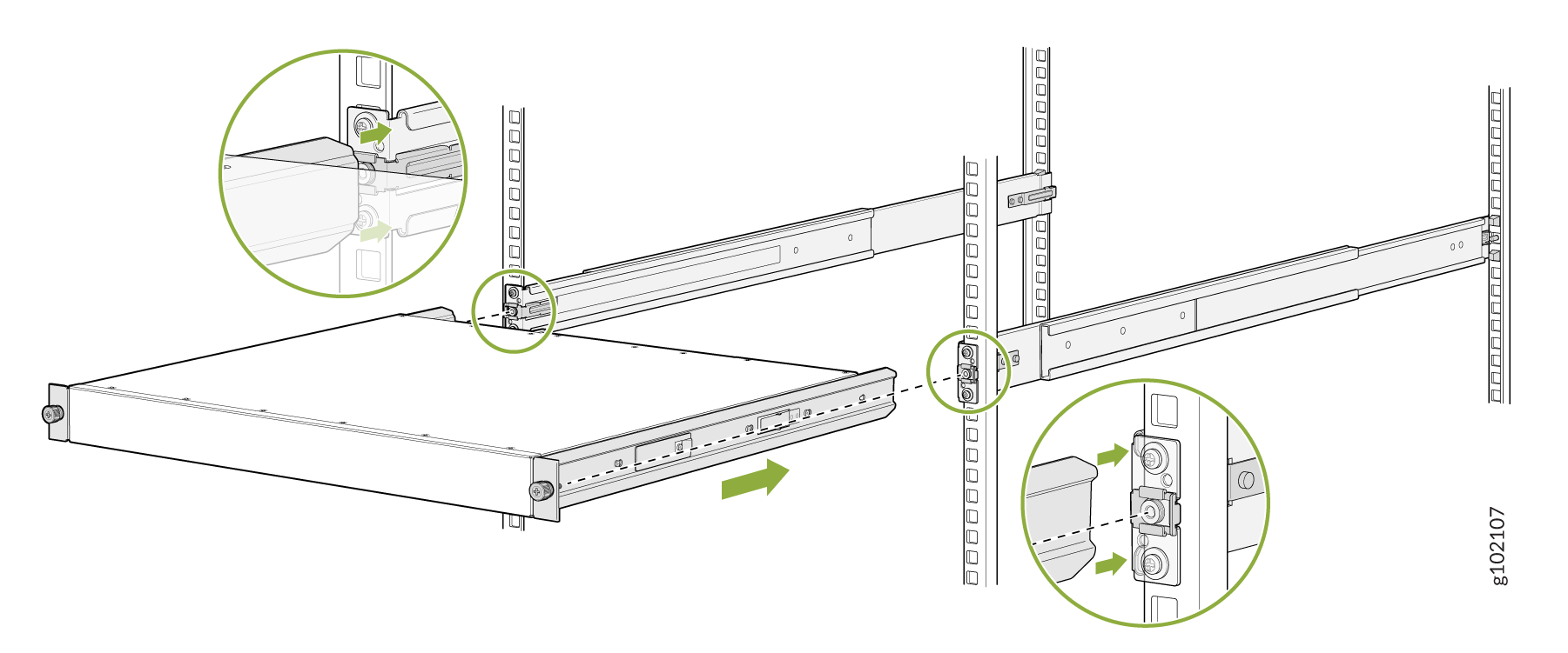
-
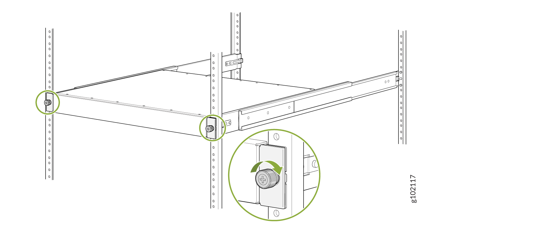
Tighten the two thumbscrews to secure the device.
Figure 13: Tighten the Thumbscrews

Mount a QFX5120-32C by Using the QFX5120-32C-RMK-E Rack Mount Kit on a Threaded-Hole 4-Post Rack
Ensure that you have the following tools and parts available:
-
An ESD grounding strap—not provided.
-
QFX5120-32C-RMK-E Rack Mount Kit
To mount the device on a four-post rack with threaded holes:
-
To attach the side mounting brackets to the chassis, align the keyholes on the mounting
brackets over the shoulder screws on the chassis. Slide the mounting brackets toward the
rear of the chassis.
Figure 14: Attach the Side Mounting Brackets
-
Assemble the mounting rails:
-
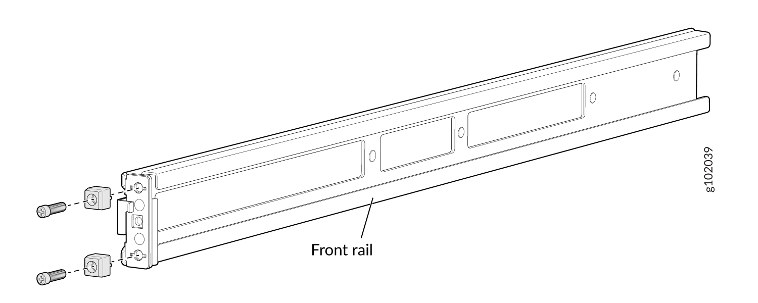
Remove the guide blocks from the front mounting rails by loosening the screws and
washers. Preserve the guide blocks, screws, and washers for later use.
Figure 15: Remove the Guide Blocks from the Front Mounting Rail

-
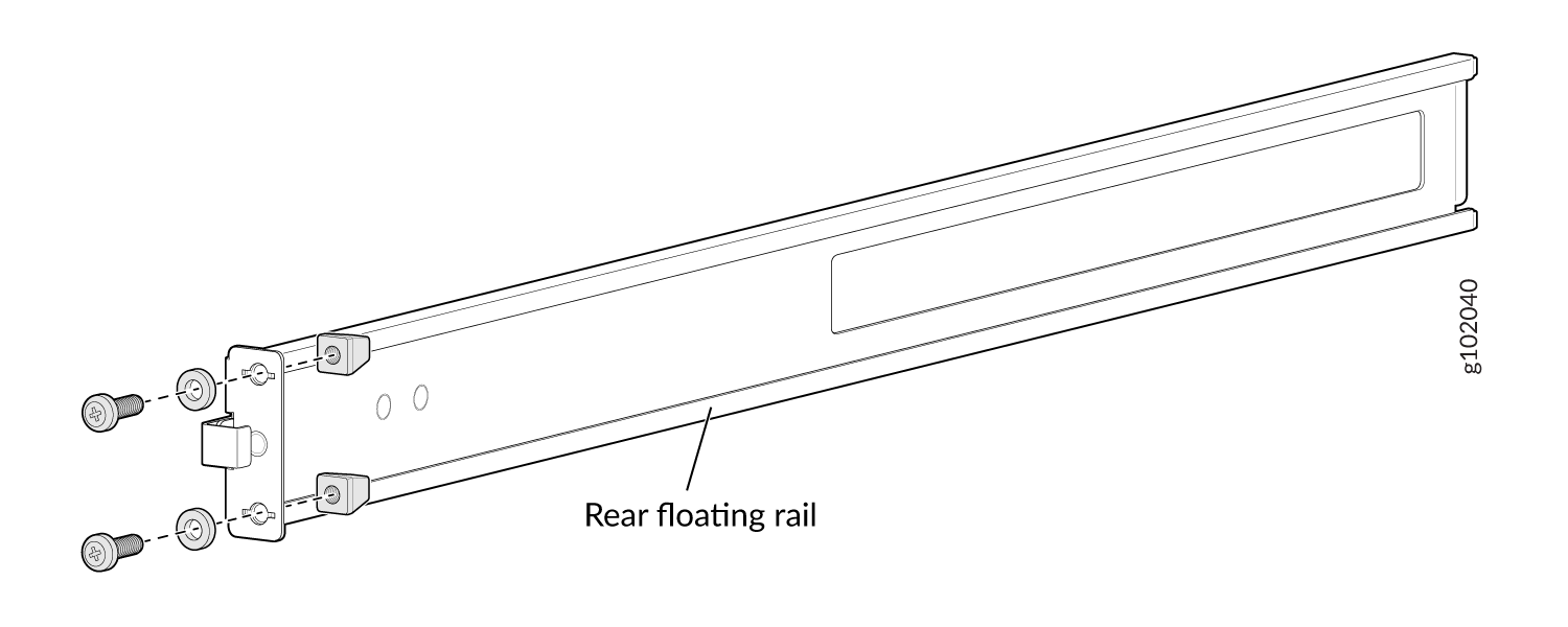
Remove the guide blocks from the rear mounting rail by loosening the screws and
washers. Preserve the guide blocks, screws, and washers for later use.
Figure 16: Remove the Guide Blocks from the Rear Mounting Rail

-
Slide the rear floating rails into the front rails.
Figure 17: Assemble the Mounting Rails
-
Remove the guide blocks from the front mounting rails by loosening the screws and
washers. Preserve the guide blocks, screws, and washers for later use.
-
Install the mounting rails on the rack:
-
Insert the guide pin of the rear mounting rails into the rear-post holes. Pull the
rear mounting rails toward the front of the rack to lock the rails in place. You will
hear a distinct click sound when the latch locks into place.
Figure 18: Install the Rear Mounting Rails

-
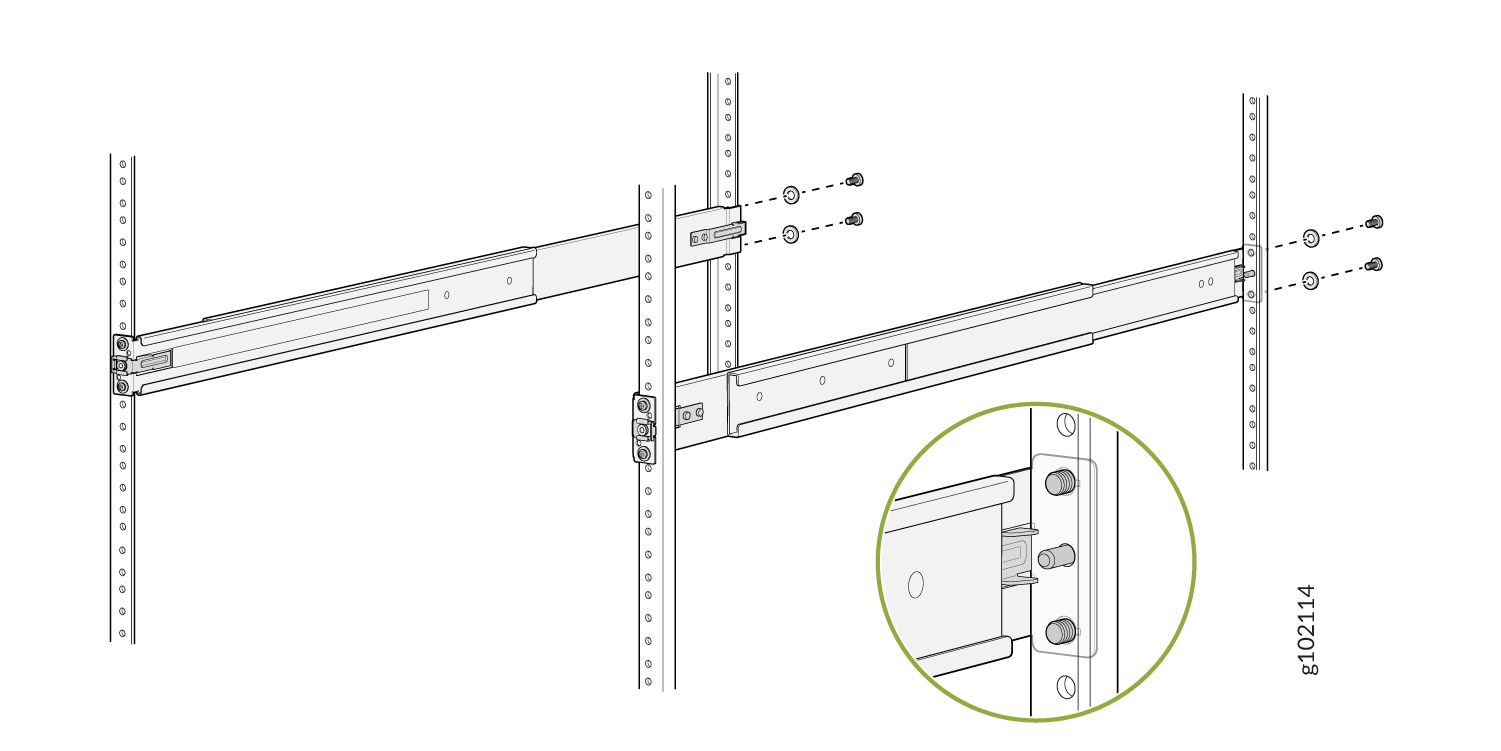
Insert the guide pin of the front mounting rails into the front-post holes. Push
the front mounting rails toward the rear of the rack to lock the rails in place. You
will hear a distinct click sound when the latch locks into place. Secure the front
mounting rails to the front rack post by using screws (not provided) appropriate for
your rack threaded size.
Figure 19: Install and Secure the Front Mounting Rails

-
Secure the rear mounting rails to the rear rack post by using screws (not provided)
appropriate for your rack threaded size.
Figure 20: Secure the Rear Mounting Rails
-
Visually ensure that the front and rear latches are locked into place on the
mounting rails. The mounting rails should be securely installed on the rack.
Figure 21: Mounting Rails Installed and Secured

-
Insert the guide pin of the rear mounting rails into the rear-post holes. Pull the
rear mounting rails toward the front of the rack to lock the rails in place. You will
hear a distinct click sound when the latch locks into place.
-
Lift the device and position it in the rack, aligning the side mounting brackets with
the mounting rails. Slide the device into the channels of the rack mounting rails.
Figure 22: Slide the Device into the Rack
-
Tighten the two thumbscrews to secure the device.
Figure 23: Tighten the Thumbscrews
Mount a QFX5120-48T, QFX5120-48Y, or QFX5120-48YM Switch in a Rack or Cabinet by Using the JNP-4PST-RMK-1U-E Rack Mount Kit
You can mount QFX5120-48T,QFX5120-48Y, or QFX5120-48YM switches on a square hole or threaded hole four-post 19-in. racks using the partial tool less JNP-4PST-RMK-1U-E rack mount kit.
JNP-4PST-RMK-1U-E rack mount kit consists of the following parts:
-
A pair of front and rear mounting rails
-
A pair of mounting brackets
-
16 flat head M4 x 6mm Phillips screws
A four-post installation evenly supports the device by all four corners.
- Mount the Device by Using the JNP-4PST-RMK-1U-E Rack Mount Kit On a Square Hole Rack
- Mount the Device by Using the JNP-4PST-RMK-1U-E Rack Mount Kit On a Threaded Hole Rack
Mount the Device by Using the JNP-4PST-RMK-1U-E Rack Mount Kit On a Square Hole Rack
Ensure that you have the following tools and parts available:
-
An ESD grounding strap—not provided.
-
Number 2 Phillips (+) screwdriver—not provided
-
A pair of front and rear mounting rails that attach to the rack posts—provided with the rack mount kit
-
A pair of mounting brackets and 16 flat head M4 x 6mm Phillips screws. These brackets attach to the device if not pre-installed—provided with the rack mount kit
To mount the device on four posts in a rack by using the JNP-4PST-RMK-1U-E rack mount kit:
- Assemble the mounting rails.
-
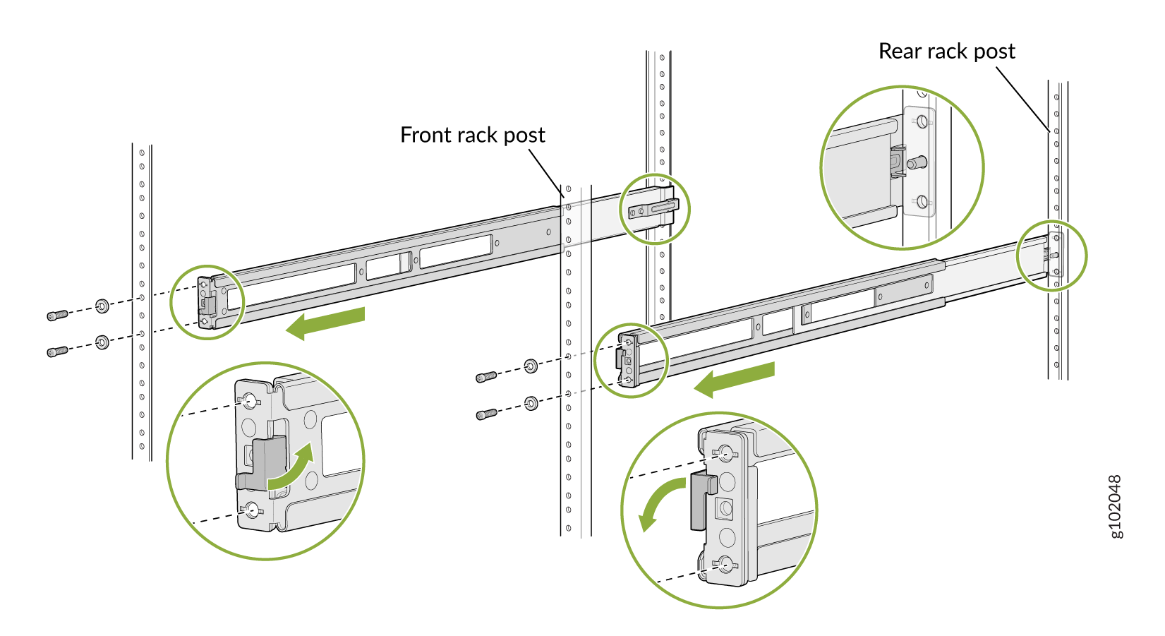
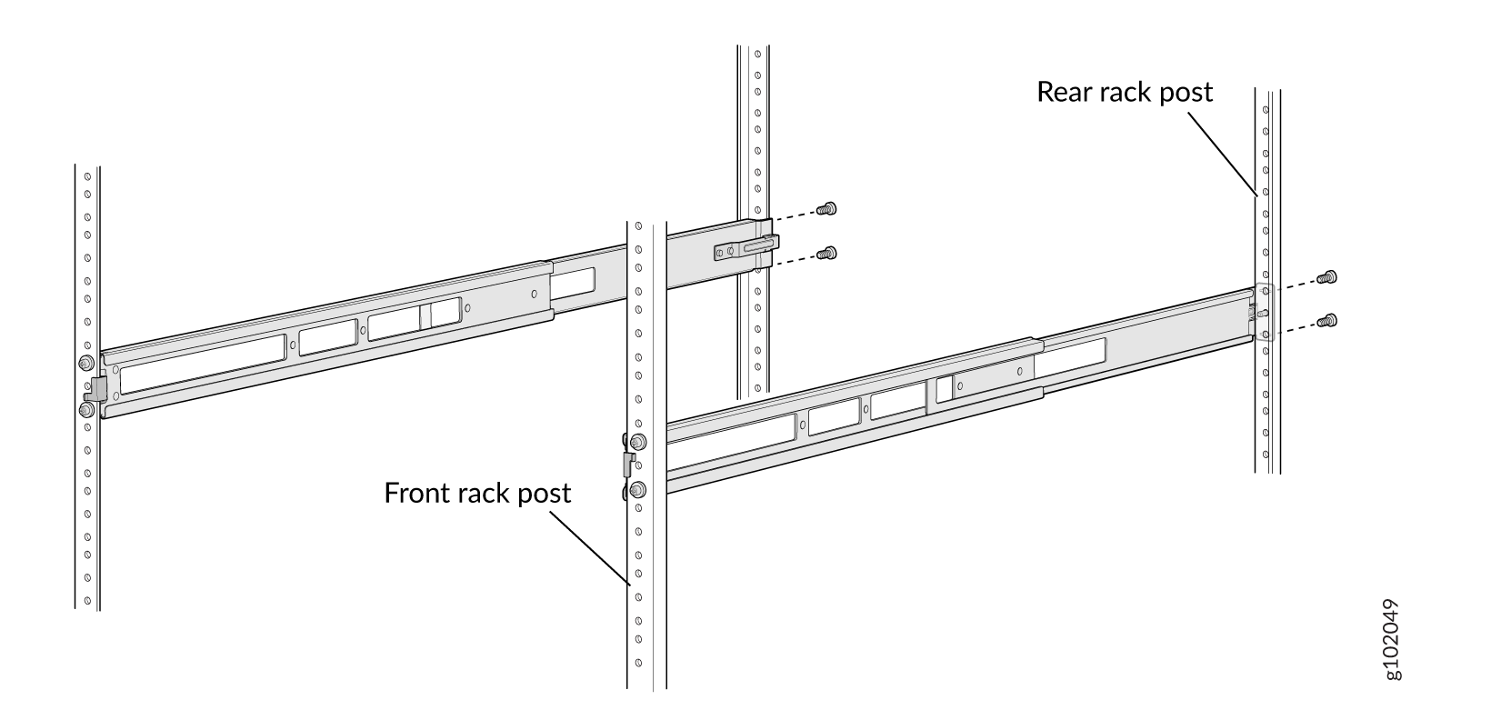
Attach the mounting rails to the rack.
-
Align the guide blocks of the rear mounting rails with the rear-post holes. Pull
the rear mounting rails toward the front of the rack to lock the rails in place. You
will hear a click sound when the latch locks into the corresponding rack holes. See
Figure 26.
Figure 26: Install the Rear Floating Rails
-
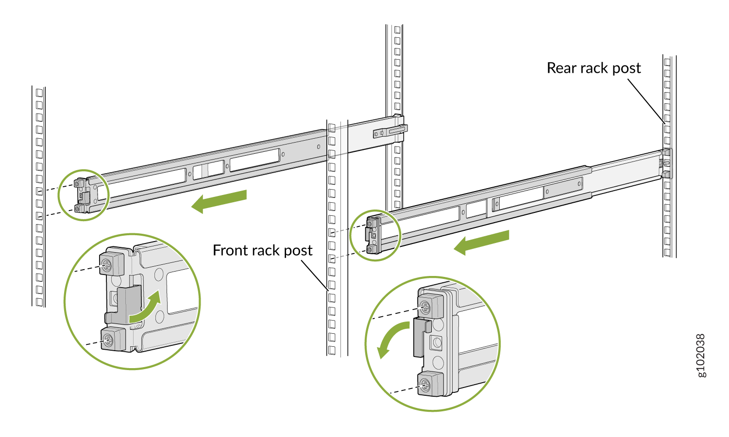
Move the latch lock on the front mounting rails to open position, slide the front
mounting rails, and insert the guide blocks into the front rack posts. See Figure 27.
Figure 27: Install the Front Mounting Rails
-
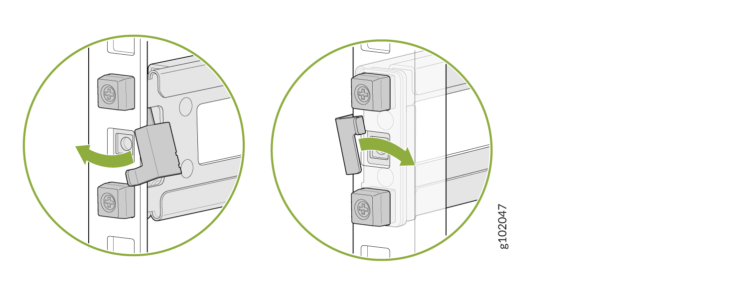
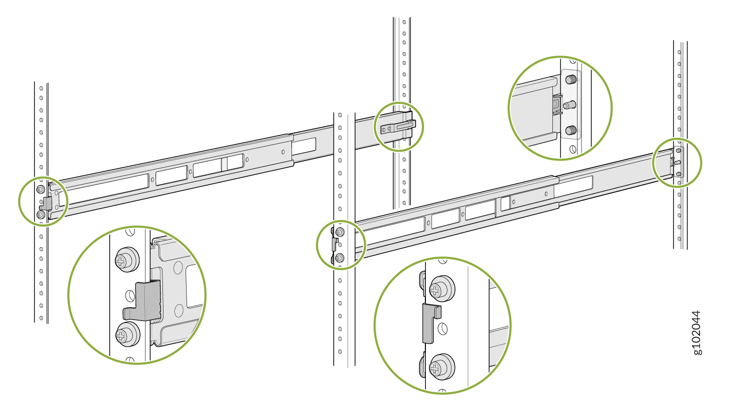
Push the lock latch to the locked position. See Figure 28.
Figure 28: Front Mounting Rails Lock Latch
-
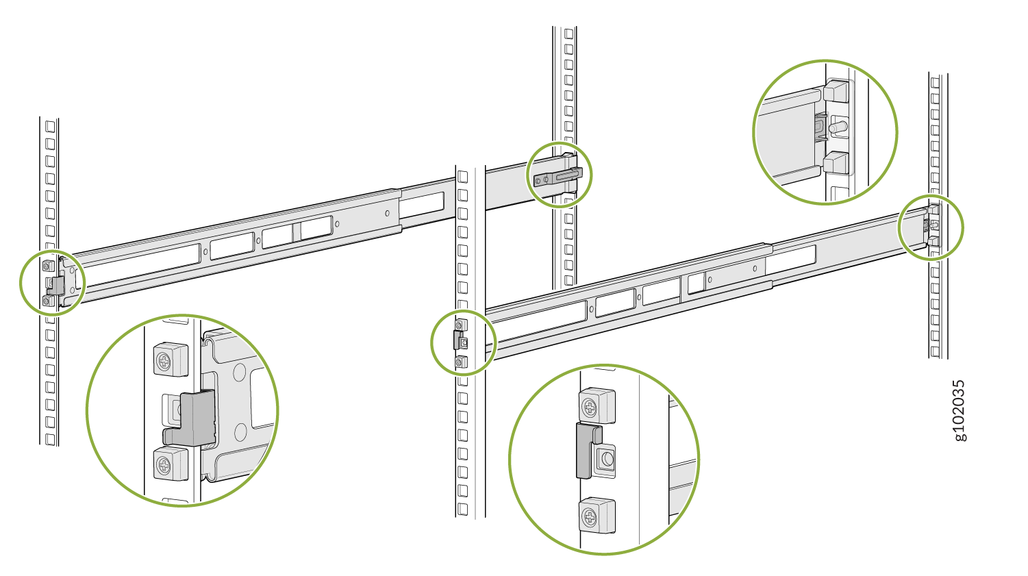
Visually ensure that the front and rear latches are locked into place on the
mounting rails. See Figure 29.
Figure 29: Mounting Rails Installed and Locked
-
Align the guide blocks of the rear mounting rails with the rear-post holes. Pull
the rear mounting rails toward the front of the rack to lock the rails in place. You
will hear a click sound when the latch locks into the corresponding rack holes. See
Figure 26.
-
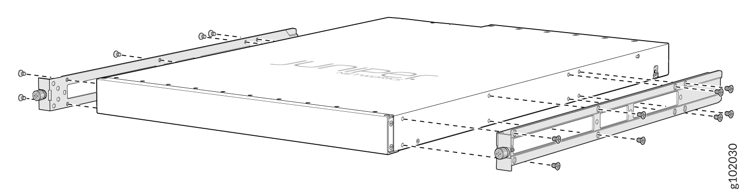
Attach mounting brackets to the device if not pre-installed. If your device already has
the mounting brackets pre-installed than skip this step and move to the next step.
-
Insert the flat head M4 x 6mm Phillips screws to attach the mounting bracket into
the aligned holes on the chassis (see Figure 30). Tighten the screws.
Figure 30: Attach the Mounting Brackets to the Device
-
Insert the flat head M4 x 6mm Phillips screws to attach the mounting bracket into
the aligned holes on the chassis (see Figure 30). Tighten the screws.
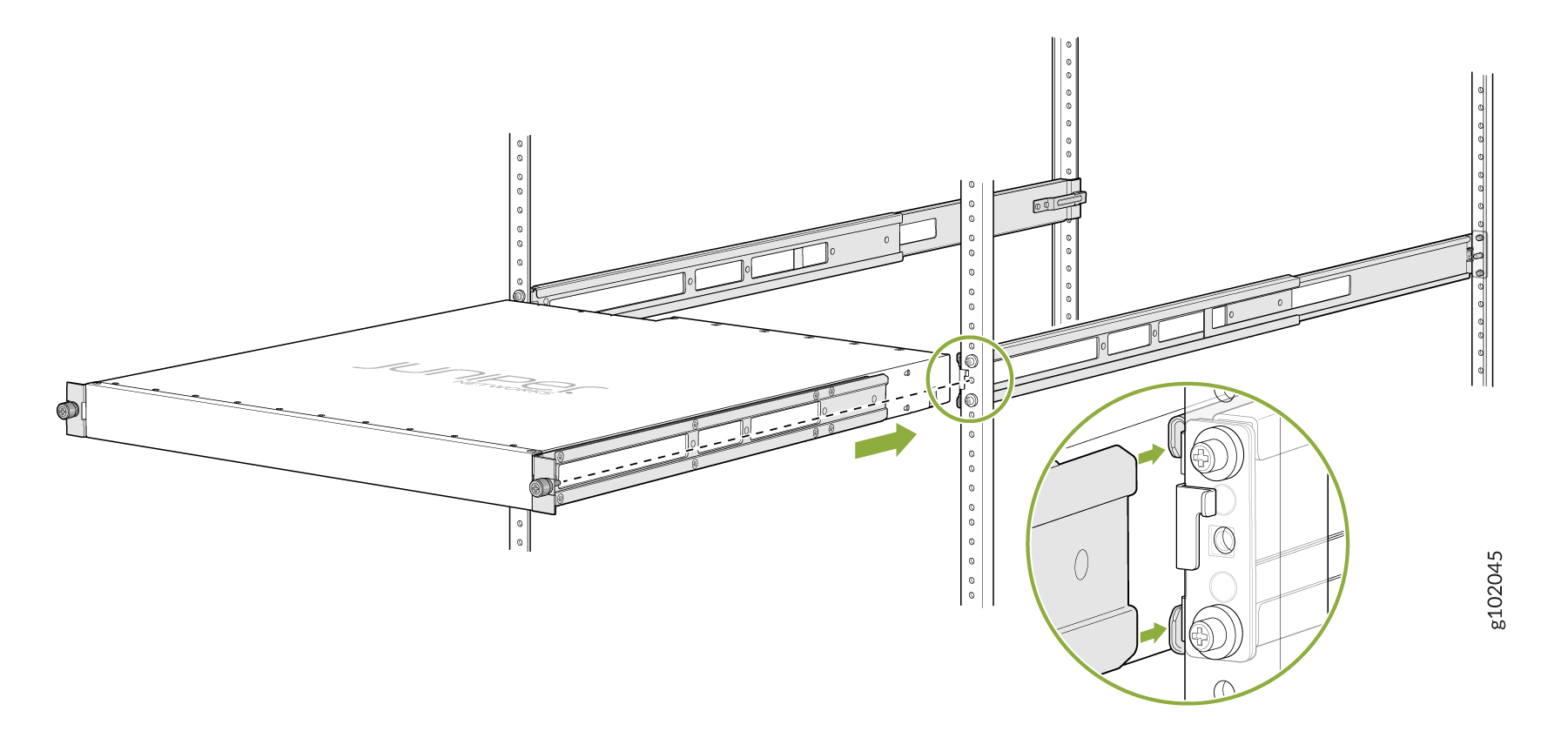
-
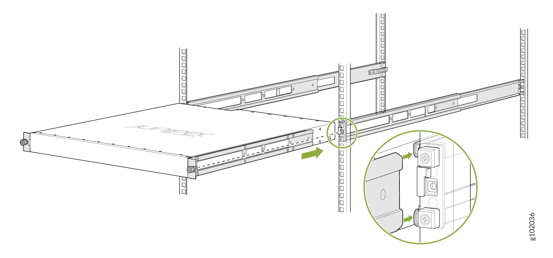
Grasp both sides of the device, lift it, and position the device such that the mounting
rails slide into the channels of the mounting brackets. See Figure 31.
Figure 31: Slide the Device into the Rack
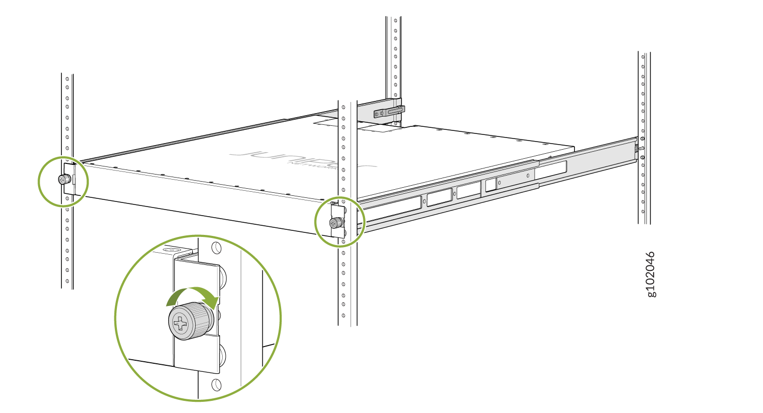
-
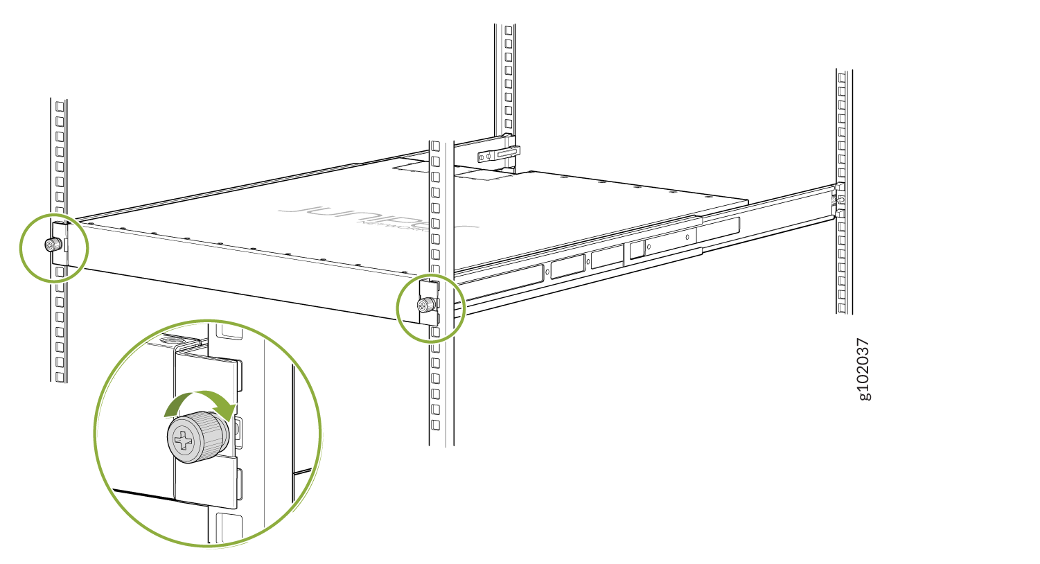
Tighten the two thumbscrews to secure the device. See Figure 32.
Figure 32: Tighten the Thumb Screws
Mount the Device by Using the JNP-4PST-RMK-1U-E Rack Mount Kit On a Threaded Hole Rack
Ensure that you have the following tools and parts available:
-
An ESD grounding strap—not provided
-
Number 2 Phillips (+) screwdriver—not provided
-
A pair of front and rear mounting rails that attach to the rack posts—provided with the rack mount kit
-
A pair of side mounting brackets and 16 flat head M4 x 6mm Phillips screws. These brackets attach to the device if not pre-installed—provided with the rack mount kit
To mount the device on four posts in a threaded hole rack by using the JNP-4PST-RMK-1U-E rack mount kit:
-
Assemble the mounting rails.
-
Remove the guide blocks from the front mounting rails by loosening the screws and
preserve them for later use. See Figure 33.
Figure 33: Remove Guide Blocks from Front Mounting Rail
-
Remove the guide blocks from the rear floating rails by loosening the screws and
washers. Preserve the guide blocks, screws, and washers for later use. See Figure 34
Figure 34: Remove Guide Blocks from Rear Floating Rail
-
Slide the rear floating rails into the front mounting rails. See Figure 35.
Figure 35: Slide Rear Floating Rail into Front Mounting Rail
-
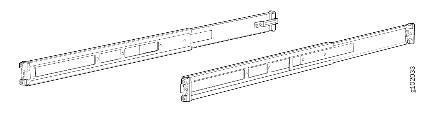
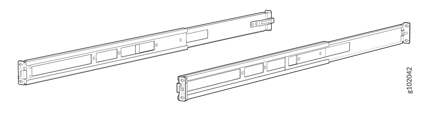
Mounting rails assembled. See Figure 36.
Figure 36: Front and Rear Rails Assembled
-
Remove the guide blocks from the front mounting rails by loosening the screws and
preserve them for later use. See Figure 33.
-
Attach the mounting rails to the threaded hole rack.
-
Align the guide blocks of the rear mounting rails with the rear-post holes. Pull
the rear mounting rails toward the front of the rack to lock the rails in place. You
will hear a click sound when the latch locks into the corresponding rack holes. See
Figure 37.
Figure 37: Install the Rear Floating Rails
-
Move the latch locks on the front mounting rails to open position, slide the front
mounting rails and align them to the front rack post. Push the lock latch to locked
position and using the screws removed in step 2.a and
the washers removed in step 2.b,
secure the front mounting rails to the front rack post. See Figure 38.
Figure 38: Install the Front Mounting Rails
-
Secure the rear floating rails to the rear rack post by using screws (not provided)
appropriate for your rack threaded size. See Figure 39.
Figure 39: Secure the Rear Floating Rails
-
Visually ensure that the front and rear latches are locked into place on the
mounting rails. See Figure 40.
Figure 40: Mounting Rails Installed and Secured
-
Align the guide blocks of the rear mounting rails with the rear-post holes. Pull
the rear mounting rails toward the front of the rack to lock the rails in place. You
will hear a click sound when the latch locks into the corresponding rack holes. See
Figure 37.
-
Attach mounting brackets to the device if not pre-installed. If your device already has
the mounting brackets pre-installed than skip this step and move to the next step.
-
Insert the flat head M4 x 6mm Phillips screws to attach the mounting bracket into
the aligned holes on the chassis (see Figure 41). Tighten the screws.
Figure 41: Attach the Mounting Brackets to the Device
-
Insert the flat head M4 x 6mm Phillips screws to attach the mounting bracket into
the aligned holes on the chassis (see Figure 41). Tighten the screws.
-
Grasp both sides of the device, lift it, and position the device such that the mounting
rails slide into the channels of the mounting brackets. See Figure 42.
Figure 42: Slide the Device into the Rack
-
Tighten the two thumbscrews to secure the device. See Figure 43.
Figure 43: Tighten Thumb Screws
Mount a QFX5120-48T, QFX5120-48Y, or QFX5120-48YM Switch Flush with the Front Posts of a Rack or Cabinet by Using the EX-4PST-RMK Rack Mount Kit
The protective earthing terminal on QFX5120-48T, QFX5120-48Y, and QFX5120-48YM switches mounted flush with the front posts of a rack is accessible through the slot on the left rear bracket only if the distance between the front posts and the rear posts is 23 in. (58.5 cm) through 30.25 in. (76.8 cm).
Before you mount a QFX5120-48T, QFX5120-48Y, or QFX5120-48YM switch:
-
Verify that the site meets the requirements described in Site Preparation Checklist for QFX5120 Switches.
-
Place the rack in its permanent location, allowing adequate clearance for airflow and maintenance, and secure the rack to the building structure.
-
Read General Safety Guidelines and Warnings, with particular attention to Chassis and Component Lifting Guidelines.
-
Ensure that you have taken the necessary precautions to prevent electrostatic discharge (ESD) damage (see Prevention of Electrostatic Discharge Damage).
-
Remove the switch from the shipping carton (see Unpack the QFX5120 Switch).
Ensure that you have the following parts and tools available:
-
Number 2 Phillips (+) screwdriver—not provided
-
Eight screws to secure the mounting brackets to the rack—not provided
-
Electrostatic discharge (ESD) grounding strap—not provided
-
Front mounting bracket assembly for mounting the switch flush with the front posts of a rack—2 (provided with the four-post rack mount kit)
(The front mounting bracket assembly is made up of a side rail to which an L-shaped bracket is attached.)
-
Flat head 4x6-mm Phillips screws for attaching the front mounting brackets to the chassis—12 (provided with the four-post rack mount kit)
-
Rear mounting brackets—2 (provided with the four-post rack mount kit)
You can mount a QFX5120 switch on four posts of a four-post 19-in. rack or in a cabinet that contains a four-post 19-in. rack, flush with the front posts, by using a four-post rack mount kit. (The remainder of this topic uses rack to mean rack or cabinet.) You can mount QFX5120-48T, QFX5120-48Y, and QFX5120-48YM switches in a recessed position inside a four-post rack by using the recessed mounting brackets. You can also mount QFX5120-48YM switches on a two-post rack by using a separately orderable two-post rack mount kit.
This topic describes the procedure to mount QFX5120-48T, QFX5120-48Y, and QFX5120-48YM switches flush with the front posts of a four-post rack. If you want to mount the switch in a recessed position from the front posts of a four-post rack, see Mount a QFX5120-48T, QFX5120-48Y, or QFX5120-48YM Switch in a Recessed Position from the Front Posts of a Rack or Cabinet. If you want to mount a QFX5120-48YM switch on a two-post rack, see Mount a QFX5120-48YM Switch on a Two-Post Rack.
One person must be available to lift the switch while another person secures the switch to the rack.
If you are mounting multiple units on a rack, mount the heaviest unit at the bottom of the rack, and then mount the other units from the bottom of the rack to the top in decreasing order of the weight of the units.
To mount a QFX5120-48T, QFX5120-48Y, or QFX5120-48YM switch flush with the front posts of a four-post rack:
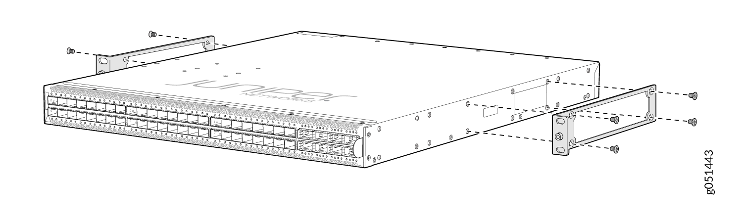
-
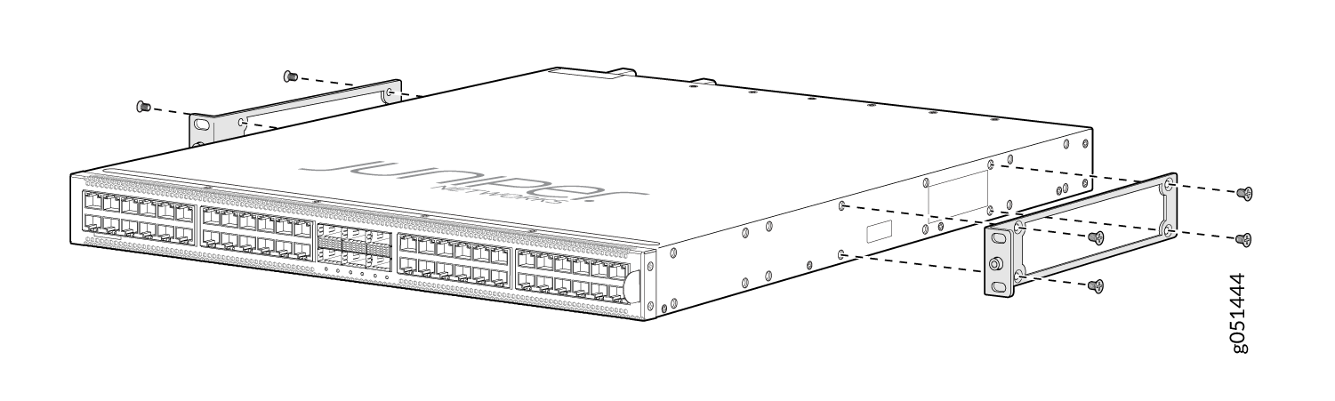
Insert the flat head 4x6-mm Phillips screws for attaching
the front mounting brackets (provided with the four-post rack mount
kit) into the aligned holes on the chassis (see Figure 44, Figure 45, and Figure 46). Tighten
the screws.
Figure 44: Attach the Flush Mounting Brackets to a QFX5120-48T Switch Chassis
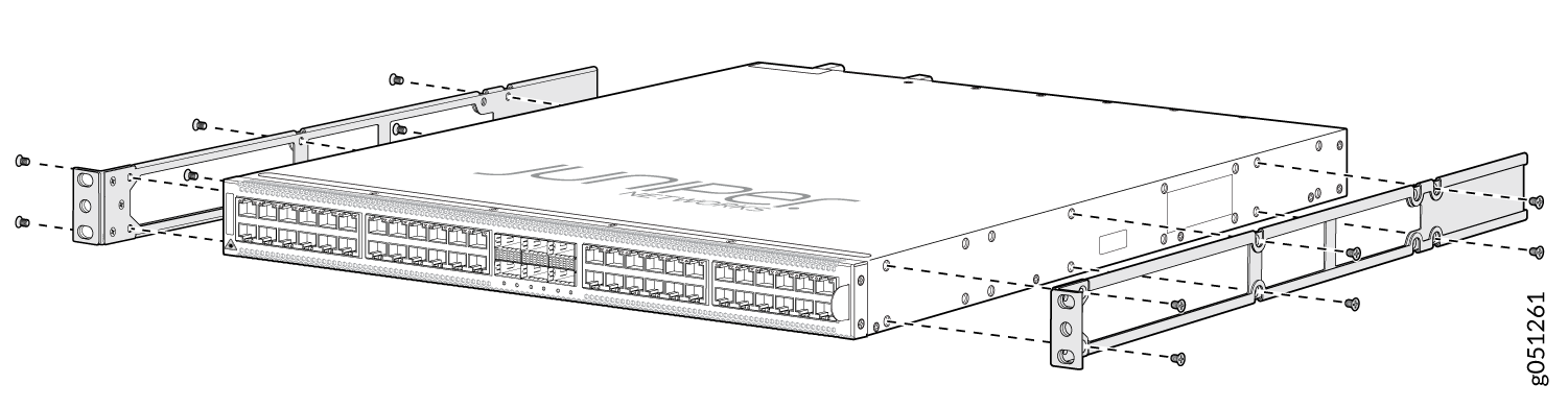 Figure 45: Attach the Flush Mounting Brackets to a QFX5120-48Y Switch Chassis
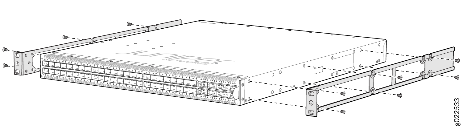 Figure 46: Attach the Flush Mounting Brackets to a QFX5120-48YM Switch Chassis
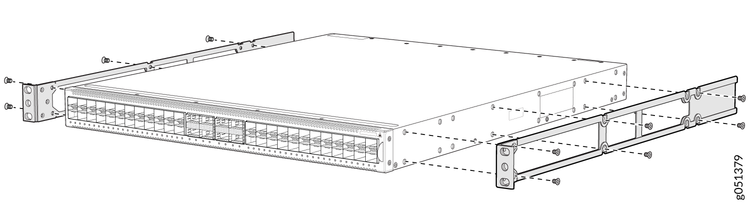
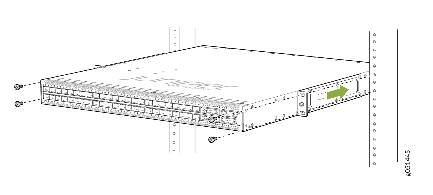
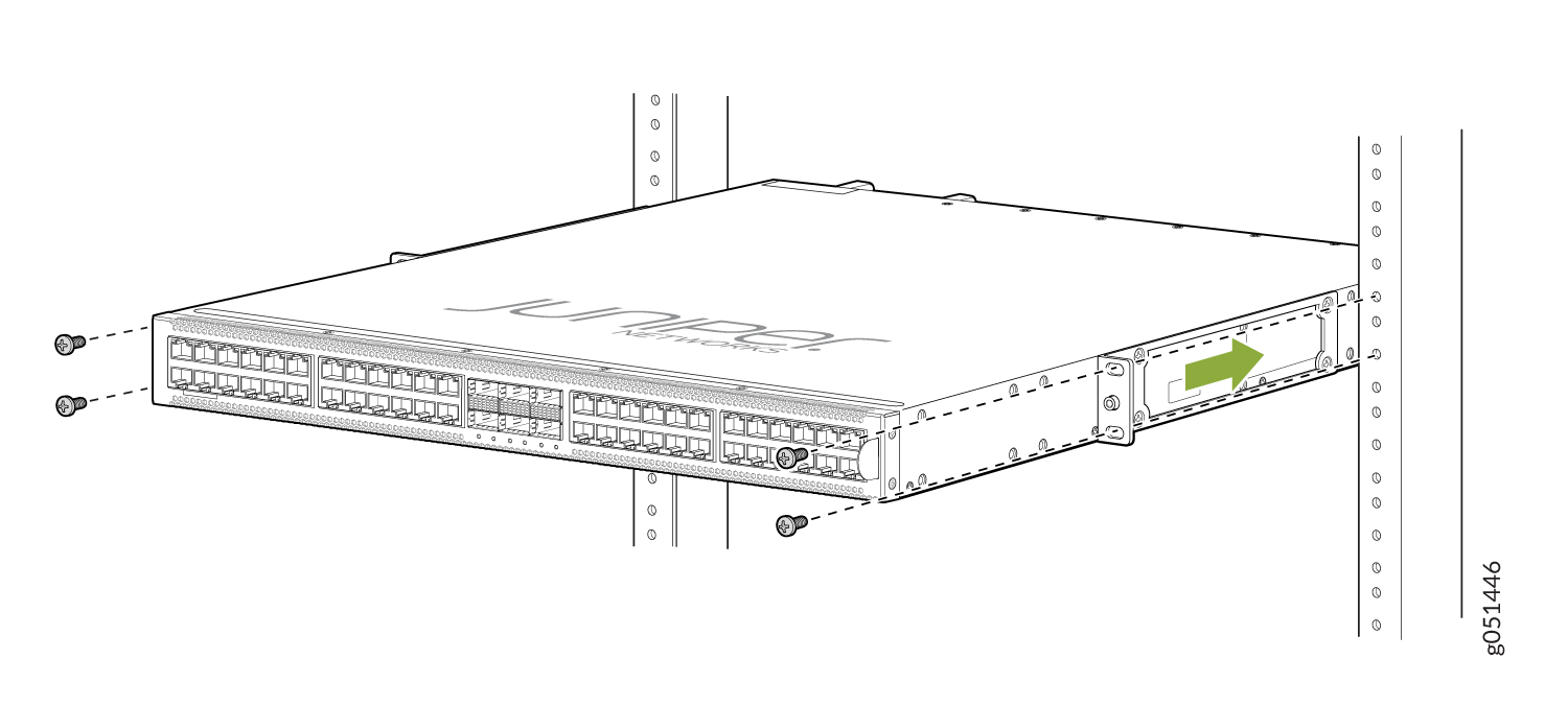
-
Have a second person secure the front of the switch to
the rack by using the screws appropriate for your rack. Tighten the
screws (see Figure 47, Figure 48, and Figure 49).
Figure 47: Secure the QFX5120-48T Switch to the Front Posts of a Rack
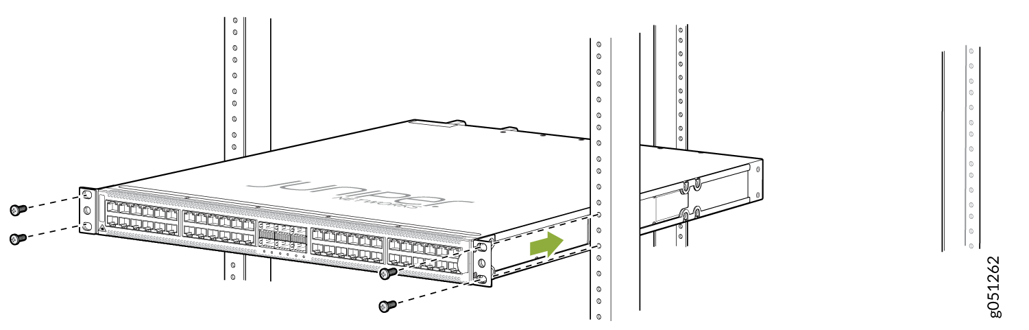 Figure 48: Secure the QFX5120-48Y Switch to the Front Posts of a Rack
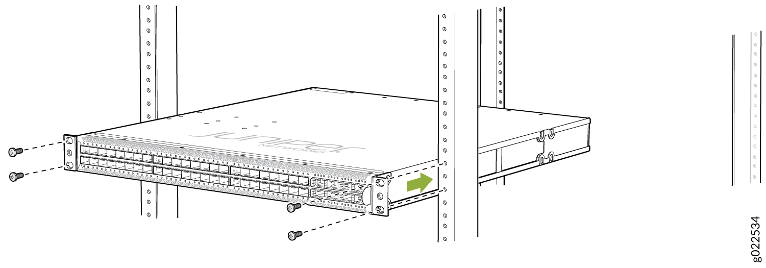 Figure 49: Secure the QFX5120-48YM Switch to the Front Posts of a Rack
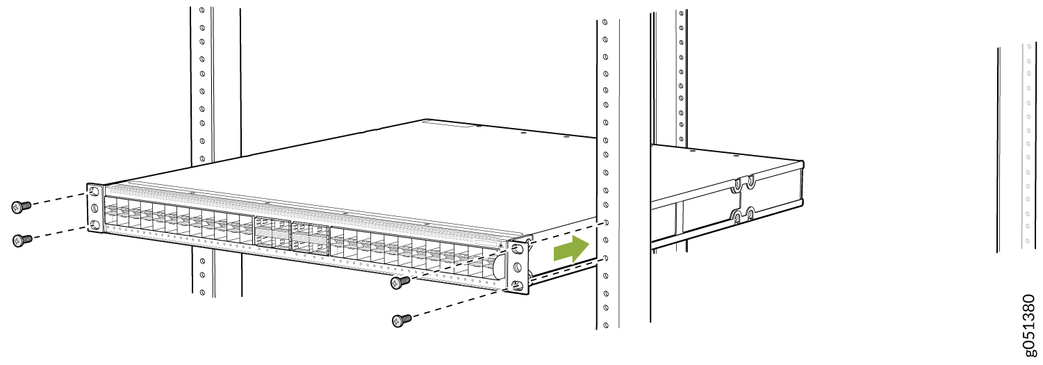
-
Secure the rear mounting brackets to the rear post of
the rack by using screws appropriate for your rack (see Figure 50, Figure 51, and Figure 52).
Figure 50: Secure the QFX5120-48T Switch to the Rear Post of the Rack by Using the Rear Mounting Brackets
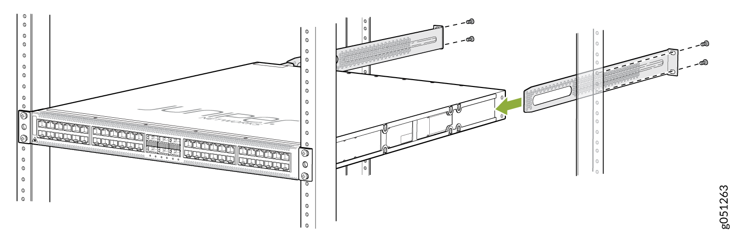 Figure 51: Secure the QFX5120-48Y Switch to the Rear Post of the Rack by Using the Rear Mounting Brackets
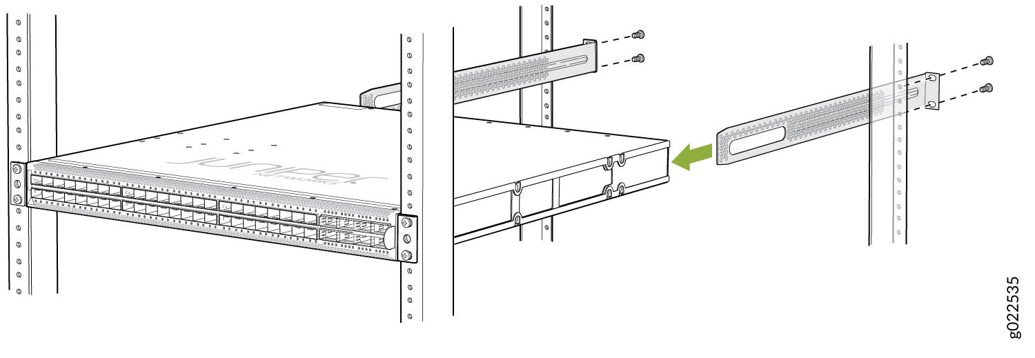 Figure 52: Secure the QFX5120-48YM Switch to the Rear Post of the Rack by Using the Rear Mounting Brackets
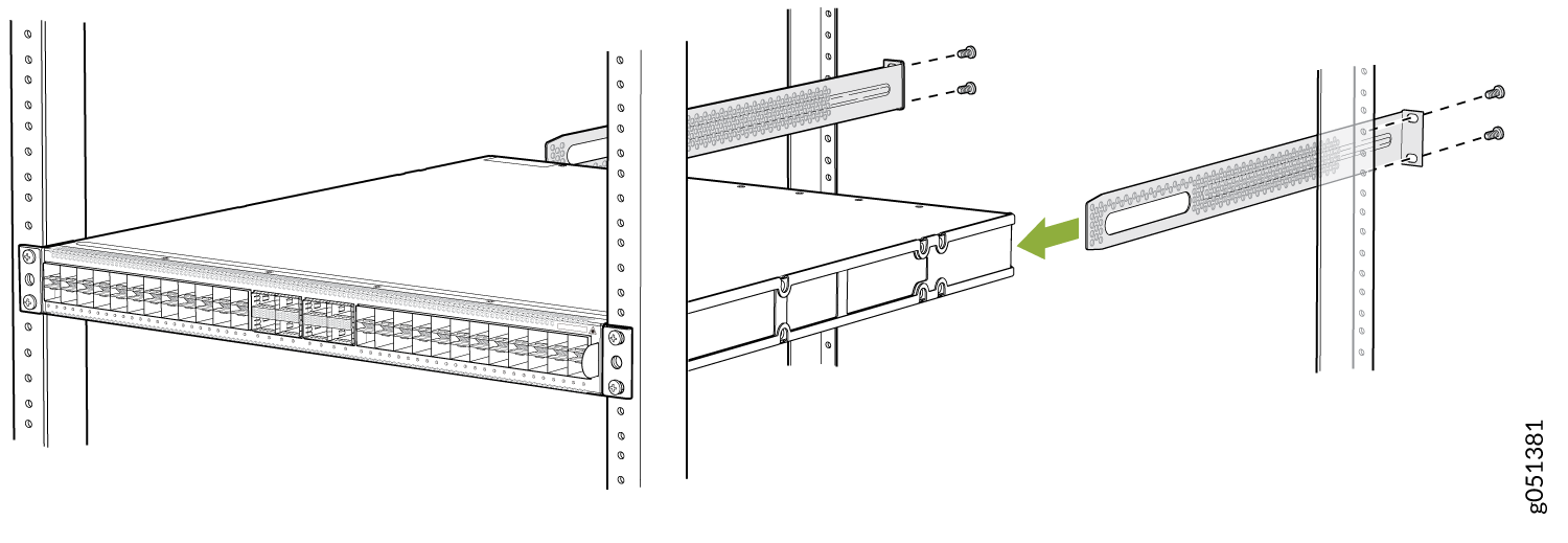
Your switch is now installed on a four-post rack.
Mount a QFX5120-48T, QFX5120-48Y, or QFX5120-48YM Switch in a Recessed Position from the Front Posts of a Rack or Cabinet by Using the EX-4PST-RMK Rack Mount Kit
The protective earthing terminal on QFX5120-48T, QFX5120-48Y, and QFX5120-48YM switches mounted in a recessed position from the front posts of a rack is accessible through the slot on the left rear bracket only if the distance between the front posts and the rear posts is 25 in. (63.5 cm) through 32.25 in. (81.9 cm).
Before you mount a QFX5120-48T, QFX5120-48Y, or QFX5120-48YM switch:
-
Verify that the site meets the requirements described in Site Preparation Checklist for QFX5120 Switches.
-
Place the rack in its permanent location, allowing adequate clearance for airflow and maintenance, and secure the rack to the building structure.
-
Read General Safety Guidelines and Warnings, with particular attention to Chassis and Component Lifting Guidelines.
-
Ensure that you have taken the necessary precautions to prevent electrostatic discharge (ESD) damage (see Prevention of Electrostatic Discharge Damage).
-
Remove the switch from the shipping carton (see Unpack the QFX5120 Switch).
Ensure that you have the following parts and tools available:
-
Number 2 Phillips (+) screwdriver—not provided
-
Eight screws to secure the mounting brackets to the rack—not provided
-
Electrostatic discharge (ESD) grounding strap—not provided
-
Front mounting bracket assembly for mounting the switch flush with the front posts of a rack—2 (provided with the four-post rack mount kit)
(The front mounting bracket assembly is made up of a side rail to which an L-shaped bracket is attached.)
-
Flat head 4x6-mm Phillips screws for attaching the front mounting brackets to the chassis—12 (provided with the four-post rack mount kit)
-
Rear mounting brackets—2 (provided with the four-post rack mount kit)
-
Recessed mounting brackets for mounting the switch in a recessed position from the front posts of a rack—2 (provided with the four-post rack mount kit)
-
Flat head 4-40 Phillips screws for attaching the recessed mounting brackets to the side rails—6 (provided with the four-post rack mount kit)
You can mount a QFX5120 switch on four posts of a four-post 19-in. rack or in a cabinet that contains a four-post 19-in. rack, flush with the front posts, by using a four-post rack mount kit. (The remainder of this topic uses rack to mean rack or cabinet.) You can mount QFX5120-48T, QFX5120-48Y, and QFX5120-48YM switches in a recessed position inside a four-post rack by using the recessed mounting brackets. You can also mount QFX5120-48YM switches on a two-post rack by using a separately orderable two-post rack mount kit.
This topic describes the procedure to mount QFX5120-48T, QFX5120-48Y, and QFX5120-48YM switches in a recessed position from the front posts of a four-post rack. If you want to mount the switch flush with the front posts of a four-post rack, see Mount a QFX5120-48T, QFX5120-48Y, or QFX5120-48YM Switch Flush with the Front Posts of a Rack or Cabinet. If you want to mount a QFX5120-48YM switch on a two-post rack, see Mount a QFX5120-48YM Switch on a Two-Post Rack.
One person must be available to lift the switch while another person secures the switch to the rack.
If you are mounting multiple units on a rack, mount the heaviest unit at the bottom of the rack, and then mount the other units from the bottom of the rack to the top in decreasing order of the weight of the units.
To mount a QFX5120-48T, QFX5120-48Y, or QFX5120-48YM switch in a recessed position from the front posts of a four-post rack:
-
Unscrew and detach the L-shaped bracket from the side
rail in the front mounting bracket assembly provided with the four-post
rack mount kit (see Figure 53).
Figure 53: Unscrew and Detach the L-Shaped Bracket from the Side Rail
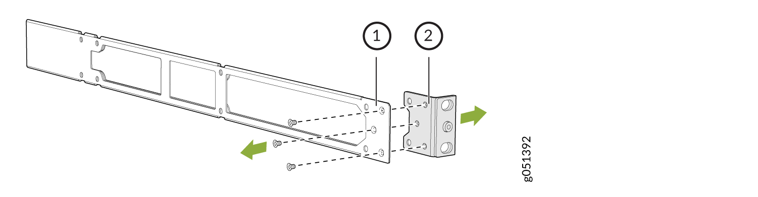 1—
1—Side rail
2—L-shaped bracket
-
Attach the recessed mounting brackets provided with the
four-post rack mount kit to the side rails by using the flat head
4-40 Phillips screws provided with the four-post rack mount kit (see Figure 54).
Figure 54: Attach the Recessed Mounting Bracket to the Side Rail
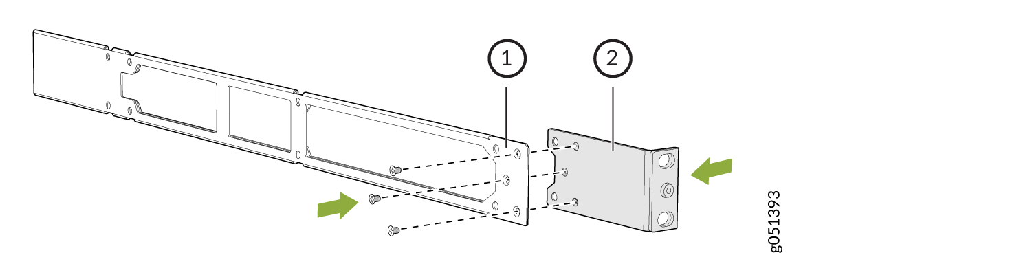 1—
1—Side rail
2—Recessed mounting bracket
-
Insert the flat head 4x6-mm Phillips screws for attaching
the recess mounting bracket assembly (provided with the four-post
rack mount kit) into the aligned holes on the chassis (see Figure 55, Figure 56, and Figure 57). Tighten the
screws.
Figure 55: Attach the Recessed Mounting Bracket Assembly to the QFX5120-48T Switch Chassis
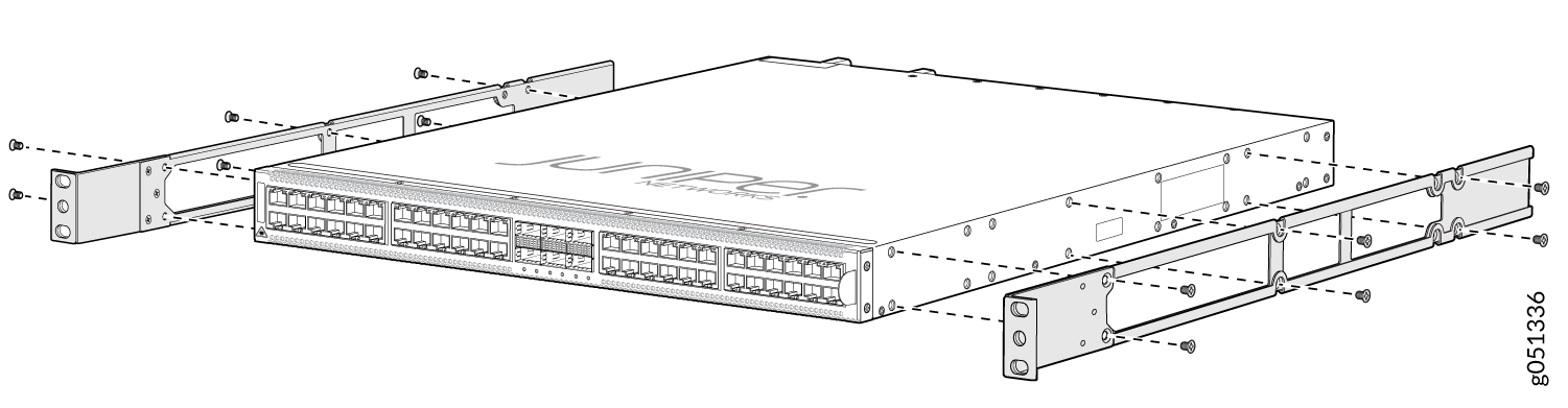 Figure 56: Attach the Recessed Mounting Bracket Assembly to the QFX5120-48Y Switch Chassis
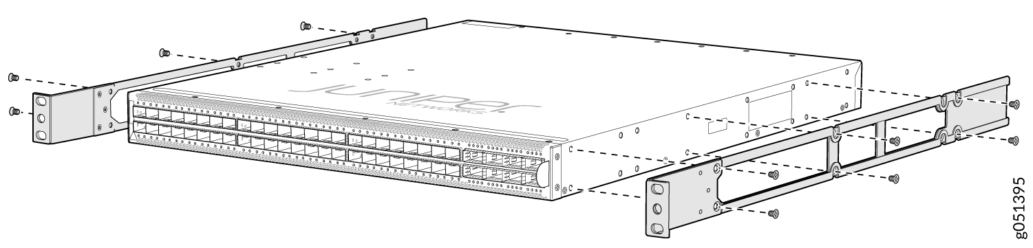 Figure 57: Attach the Recessed Mounting Bracket Assembly to the QFX5120-48YM Switch Chassis
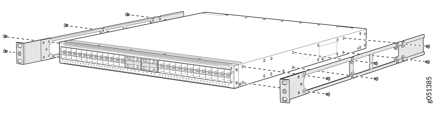
-
Have a second person secure the front of the switch to
the rack by using the screws appropriate for your rack. Tighten the
screws (see Figure 58, Figure 59, and Figure 60).
Figure 58: Secure the QFX5120-48T Switch to the Front Posts of a Rack
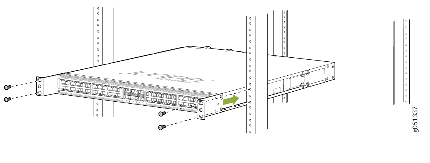 Figure 59: Secure the QFX5120-48Y Switch to the Front Posts of a Rack
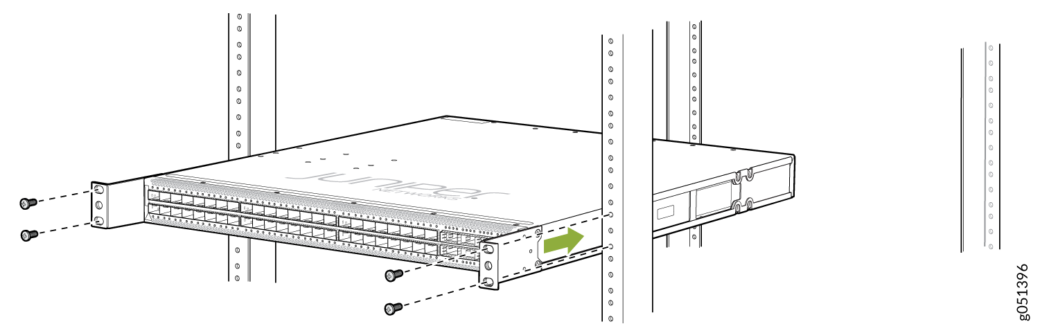 Figure 60: Secure the QFX5120-48YM Switch to the Front Posts of a Rack
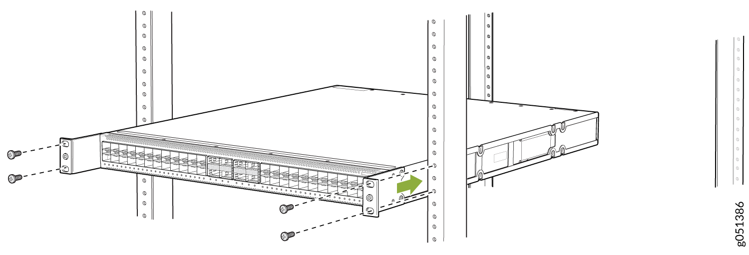
-
Secure the rear mounting brackets to the rear post of
the rack by using screws appropriate for your rack (see Figure 61, Figure 62,
and Figure 63).
Figure 61: Secure the QFX5120-48T Switch to the Rear Post of the Rack by Using the Rear Mounting Brackets
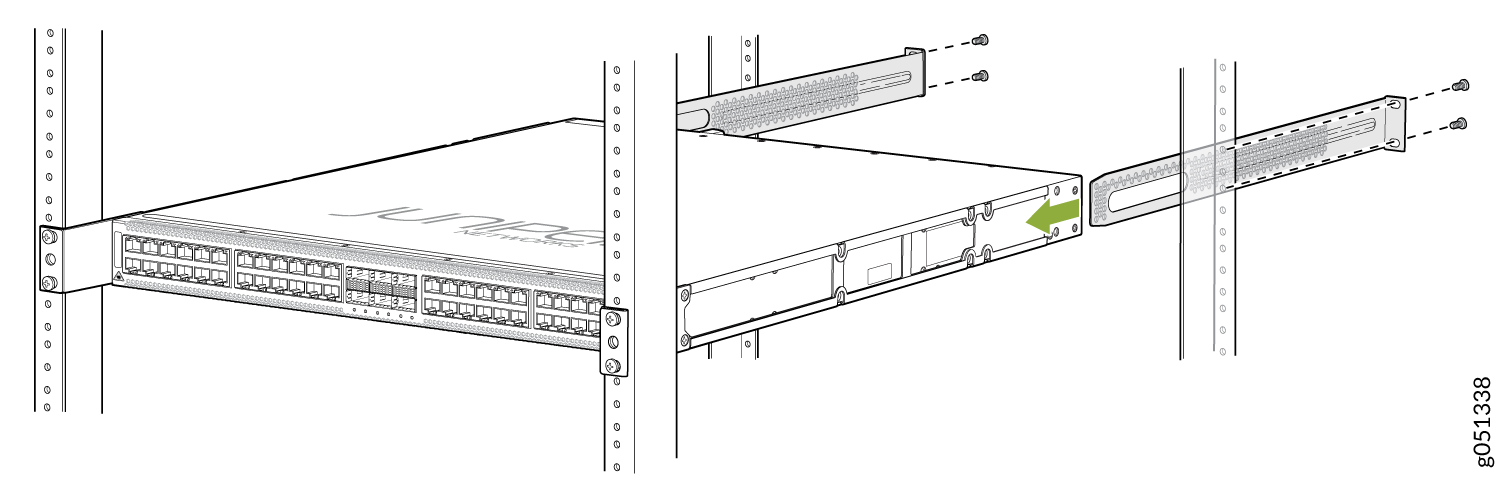 Figure 62: Secure the QFX5120-48Y Switch to the Rear Post of the Rack by Using the Rear Mounting Brackets
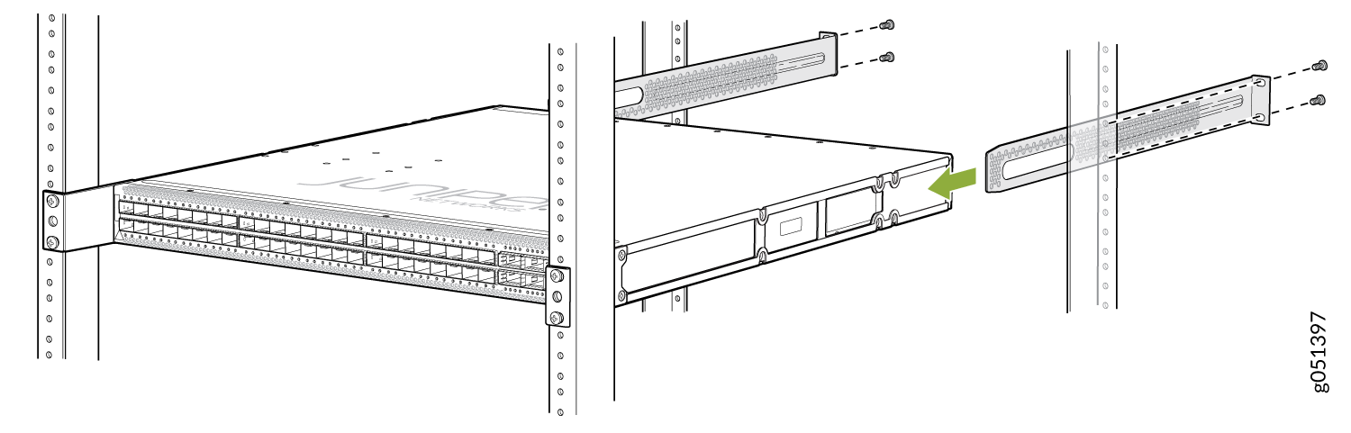 Figure 63: Secure the QFX5120-48YM Switch to the Rear Post of the Rack by Using the Rear Mounting Brackets
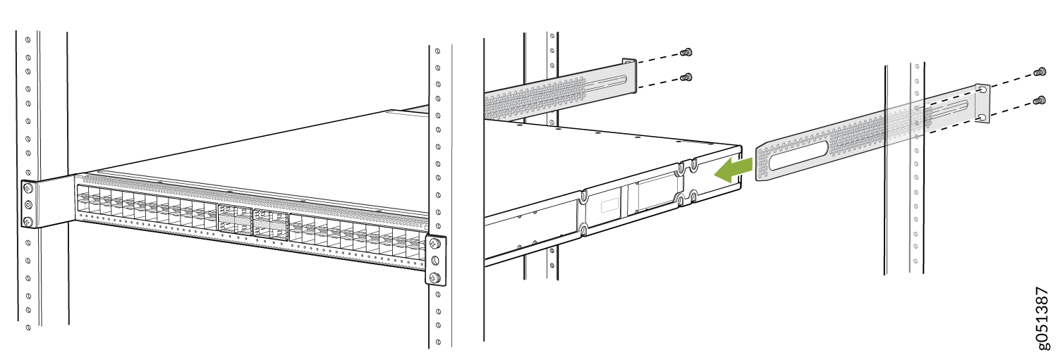
Your switch is now installed on a four-post rack.
Mount a QFX5120-48Y Switch on a Two-Post Rack
Before you mount a QFX5120-48Y switch on a two-post rack:
-
Verify that the site meets the requirements described in Site Preparation Checklist for QFX5120 Switches.
-
Place the rack in its permanent location, allowing adequate clearance for airflow and maintenance, and secure the rack to the building structure.
-
Read General Safety Guidelines and Warnings, with particular attention to Chassis and Component Lifting Guidelines.
-
Ensure that you have taken the necessary precautions to prevent electrostatic discharge (ESD) damage (see Prevention of Electrostatic Discharge Damage).
-
Remove the switch from the shipping carton (see Unpack the QFX5120 Switch).
Ensure that you have the following parts and tools available:
-
Number 2 Phillips (+) screwdriver—not provided
-
Eight screws to secure the mounting brackets to the rack—not provided
-
Electrostatic discharge (ESD) grounding strap—not provided
-
Two-post rack mounting bracket for mounting the switch on a two-post rack—2 (provided with the two-post rack mount kit)
-
Flat head 4x6-mm Phillips screws for attaching the two-post rack mounting brackets to the chassis—8 (provided with the two-post rack mount kit)
You can mount a QFX5120 switch on four posts of a four-post 19-in. rack or in a cabinet that contains a four-post 19-in. rack, flush with the front posts, by using a four-post rack mount kit. (The remainder of this topic uses rack to mean rack or cabinet.) You can mount QFX5120-48Y switches in a recessed position inside a four-post rack by using the recessed mounting brackets. You can also mount QFX5120-48Y switches on a two-post rack by using a separately orderable two-post rack mount kit.
This topic describes the procedure to mount a QFX5120-48Y switch on a two-post rack. If you want to mount the switch flush with the front posts of a four-post rack, see Mount a QFX5120-48T, QFX5120-48Y, or QFX5120-48YM Switch Flush with the Front Posts of a Rack or Cabinet. If you want to mount the switch in a recessed position from the front posts of a four-post rack, see Mount a QFX5120-48T, QFX5120-48Y, or QFX5120-48YM Switch in a Recessed Position from the Front Posts of a Rack or Cabinet.
One person must be available to lift the switch while another person secures the switch to the rack.
If you are mounting multiple units on a rack, mount the heaviest unit at the bottom of the rack, and then mount the other units from the bottom of the rack to the top in decreasing order of the weight of the units.
To mount a QFX5120-48Y switch on a two-post rack:
-
Insert the flat head 4x6-mm Phillips screws for attaching the two-post rack
mounting brackets (provided with the two-post rack mount kit) into the
aligned holes on the chassis. Tighten the screws.
Figure 64: Attach the Two-Post Rack Mounting Brackets to a QFX5120-48Y Switch Chassis
-
Have a second person secure the switch to the rack by using the screws
appropriate for your rack. Tighten the screws.
Figure 65: Secure the QFX5120-48Y Switch to the Two-Post Rack
Your switch is now installed on a two-post rack.
Mount a QFX5120-48T Switch on a Two-Post Rack
Before you mount a QFX5120-48T switch on a two-post rack:
-
Verify that the site meets the requirements described in Site Preparation Checklist for QFX5120 Switches.
-
Place the rack in its permanent location, allowing adequate clearance for airflow and maintenance, and secure the rack to the building structure.
-
Read General Safety Guidelines and Warnings, with particular attention to Chassis and Component Lifting Guidelines.
-
Ensure that you have taken the necessary precautions to prevent electrostatic discharge (ESD) damage (see Prevention of Electrostatic Discharge Damage).
-
Remove the switch from the shipping carton (see Unpack the QFX5120 Switch).
Ensure that you have the following parts and tools available:
-
Number 2 Phillips (+) screwdriver—not provided
-
Eight screws to secure the mounting brackets to the rack—not provided
-
Electrostatic discharge (ESD) grounding strap—not provided
-
Two-post rack mounting bracket for mounting the switch on a two-post rack—2 (provided with the two-post rack mount kit)
-
Flat head 4x6-mm Phillips screws for attaching the two-post rack mounting brackets to the chassis—8 (provided with the two-post rack mount kit)
You can mount a QFX5120 switch on four posts of a four-post 19-in. rack or in a cabinet that contains a four-post 19-in. rack, flush with the front posts, by using a four-post rack mount kit. (The remainder of this topic uses rack to mean rack or cabinet.) You can mount QFX5120-48T switches in a recessed position inside a four-post rack by using the recessed mounting brackets. You can also mount QFX5120-48T switches on a two-post rack by using a separately orderable two-post rack mount kit.
This topic describes the procedure to mount a QFX5120-48T switch on a two-post rack. If you want to mount the switch flush with the front posts of a four-post rack, see Mount a QFX5120-48T, QFX5120-48Y, or QFX5120-48YM Switch Flush with the Front Posts of a Rack or Cabinet. If you want to mount the switch in a recessed position from the front posts of a four-post rack, see Mount a QFX5120-48T, QFX5120-48Y, or QFX5120-48YM Switch in a Recessed Position from the Front Posts of a Rack or Cabinet.
One person must be available to lift the switch while another person secures the switch to the rack.
If you are mounting multiple units on a rack, mount the heaviest unit at the bottom of the rack, and then mount the other units from the bottom of the rack to the top in decreasing order of the weight of the units.
To mount a QFX5120-48T switch on a two-post rack:
-
Insert the flat head 4x6-mm Phillips screws for attaching the two-post
rack mounting brackets (provided with the two-post rack mount kit) into
the aligned holes on the chassis. Tighten the screws.
Figure 66: Attach the Two-Post Rack Mounting Brackets to a QFX5120-48T Switch Chassis
-
Have a second person secure the switch to the rack by using the screws
appropriate for your rack. Tighten the screws).
Figure 67: Secure the QFX5120-48T Switch to the Two-Post Rack
Your switch is now installed on a two-post rack.
Mount a QFX5120-48YM Switch on a Two-Post Rack
Before you mount a QFX5120-48YM switch on a two-post rack:
-
Verify that the site meets the requirements described in Site Preparation Checklist for QFX5120 Switches.
-
Place the rack in its permanent location, allowing adequate clearance for airflow and maintenance, and secure the rack to the building structure.
-
Read General Safety Guidelines and Warnings, with particular attention to Chassis and Component Lifting Guidelines.
-
Ensure that you have taken the necessary precautions to prevent electrostatic discharge (ESD) damage (see Prevention of Electrostatic Discharge Damage).
-
Remove the switch from the shipping carton (see Unpack the QFX5120 Switch).
Ensure that you have the following parts and tools available:
-
Number 2 Phillips (+) screwdriver—not provided
-
Eight screws to secure the mounting brackets to the rack—not provided
-
Electrostatic discharge (ESD) grounding strap—not provided
-
Two-post rack mounting bracket for mounting the switch on a two-post rack—2 (provided with the two-post rack mount kit)
-
Flat head 4x6-mm Phillips screws for attaching the two-post rack mounting brackets to the chassis—8 (provided with the two-post rack mount kit)
You can mount a QFX5120 switch on four posts of a four-post 19-in. rack or in a cabinet that contains a four-post 19-in. rack, flush with the front posts, by using a four-post rack mount kit. (The remainder of this topic uses rack to mean rack or cabinet.) You can mount QFX5120-48YM switches in a recessed position inside a four-post rack by using the recessed mounting brackets. You can also mount QFX5120-48YM switches on a two-post rack by using a separately orderable two-post rack mount kit.
This topic describes the procedure to mount a QFX5120-48YM switch on a two-post rack. If you want to mount the switch flush with the front posts of a four-post rack, see Mount a QFX5120-48T, QFX5120-48Y, or QFX5120-48YM Switch Flush with the Front Posts of a Rack or Cabinet. If you want to mount the switch in a recessed position from the front posts of a four-post rack, see Mount a QFX5120-48T, QFX5120-48Y, or QFX5120-48YM Switch in a Recessed Position from the Front Posts of a Rack or Cabinet.
One person must be available to lift the switch while another person secures the switch to the rack.
If you are mounting multiple units on a rack, mount the heaviest unit at the bottom of the rack, and then mount the other units from the bottom of the rack to the top in decreasing order of the weight of the units.
To mount a QFX5120-48YM switch on a two-post rack:
-
Insert the flat head 4x6-mm Phillips screws for attaching the two-post rack
mounting brackets (provided with the two-post rack mount kit) into the aligned
holes on the chassis). Tighten the screws.
Figure 68: Attach the Two-Post Rack Mounting Brackets to a QFX5120-48YM Switch Chassis
-
Have a second person secure the switch to the rack by using the screws
appropriate for your rack. Tighten the screws.
Figure 69: Secure the QFX5120-48YM Switch to the Two-Post Rack
Your switch is now installed on a two-post rack.