EN ESTA PÁGINA
Ejemplo: configuración de VPWS con mecanismos de señalización EVPN
En este ejemplo se muestra cómo implementar Virtual Private Wire Service (VPWS) con señalización de red privada virtual Ethernet (EVPN). El uso de la señalización EVPN proporciona capacidades de multihoming activas o totalmente activas para VPN señaladas por BGP.
Requisitos
En este ejemplo se utilizan los siguientes componentes de hardware y software:
Cuatro enrutadores serie MX que actúan como dispositivos perimetrales de proveedor (PE) con Junos OS versión 17.1 o posterior
Dos dispositivos perimetrales de cliente (CE) (en este ejemplo se utilizan enrutadores de la serie MX)
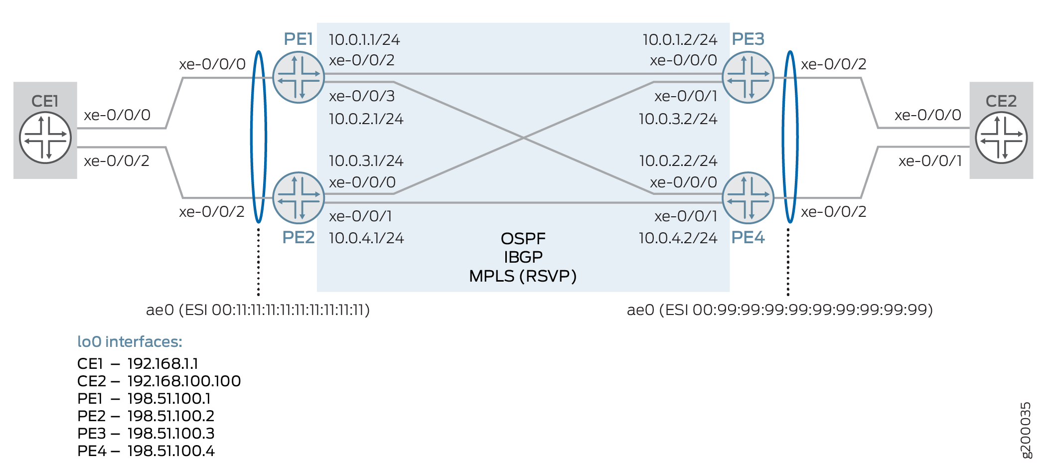
Descripción general y topología
VPWS emplea servicios VPN de capa 2 sobre MPLS para construir una topología de conexiones punto a punto que conectan los sitios de los clientes finales. EVPN le permite conectar sitios de clientes dispersos mediante un puente virtual de capa 2. A partir de Junos OS versión 17.1, estos dos elementos se pueden combinar para proporcionar un VPWS con señal EVPN.
La vpws-service-id instrucción identifica los puntos finales del EVPN-VPWS en local remote función de los identificadores de servicio configurados en los enrutadores PE de la red. Estos puntos de conexión se detectan automáticamente mediante la señalización EVPN basada en BGP para intercambiar las etiquetas del identificador de servicio.
Topología
En este ejemplo se usa la topología que se muestra en la figura 1, que consta de cuatro enrutadores PE y dos enrutadores CE. El enrutador CE1 es de multiconexión en los enrutadores PE1 y PE2; El enrutador CE2 se multiplegue a los enrutadores PE3 y PE4.
 EVPN
EVPN
En este escenario se utilizan los siguientes elementos de configuración:
Dispositivos CE:
Interfaz Ethernet (AE) agregada hacia dispositivos PE relacionados
Dispositivos de PE:
Interfaz AE, con identificador de segmento EVPN (ESI), hacia el dispositivo CE relacionado
OSPF y IBGP en el núcleo
LSP MPLS que usan RSVP en el núcleo
Equilibrio de carga por paquete
Instancia de enrutamiento mediante el tipo
evpn-vpwsde instancia y lavpws-service-idinstrucción para definir los extremos locales y remotos.
Configuración
Configuración rápida de CLI
Para configurar rápidamente este ejemplo, copie los siguientes comandos, péguelos en un archivo de texto, elimine los saltos de línea, cambie los detalles necesarios para que coincidan con su configuración de red, copie y pegue los comandos en la CLI en el nivel de [edit] jerarquía.
CE1
set interfaces xe-0/0/0 gigether-options 802.3ad ae0
set interfaces xe-0/0/2 gigether-options 802.3ad ae0
set chassis aggregated-devices ethernet device-count 1
set interfaces ae0 description "to PE1/2"
set interfaces ae0 flexible-vlan-tagging
set interfaces ae0 encapsulation flexible-ethernet-services
set interfaces ae0 aggregated-ether-options lacp active
set interfaces ae0 unit 100 encapsulation vlan-bridge
set interfaces ae0 unit 100 vlan-id 1000
set interfaces lo0 unit 0 family inet address 192.168.1.1/32
set policy-options policy-statement LB then load-balance per-packet
set routing-options forwarding-table export LB
set bridge-domains bd100 domain-type bridge
set bridge-domains bd100 vlan-id 1000
set bridge-domains bd100 interface ae0.100
CE2
set interfaces xe-0/0/0 gigether-options 802.3ad ae0
set interfaces xe-0/0/1 gigether-options 802.3ad ae0
set chassis aggregated-devices ethernet device-count 1
set interfaces ae0 description "to PE3/4"
set interfaces ae0 flexible-vlan-tagging
set interfaces ae0 encapsulation flexible-ethernet-services
set interfaces ae0 aggregated-ether-options lacp active
set interfaces ae0 unit 100 encapsulation vlan-bridge
set interfaces ae0 unit 100 vlan-id 1000
set interfaces lo0 unit 0 family inet address 192.168.100.100/32
set policy-options policy-statement LB then load-balance per-packet
set routing-options forwarding-table export LB
set bridge-domains bd100 domain-type bridge
set bridge-domains bd100 vlan-id 1000
set bridge-domains bd100 interface ae0.100
PE1
set interfaces xe-0/0/0 description "to CE1"
set interfaces xe-0/0/0 gigether-options 802.3ad ae0
set interfaces xe-0/0/2 unit 0 description "to PE3"
set interfaces xe-0/0/2 unit 0 family inet address 10.0.1.1/24
set interfaces xe-0/0/2 unit 0 family mpls
set interfaces xe-0/0/3 unit 0 description "to PE4"
set interfaces xe-0/0/3 unit 0 family inet address 10.0.2.1/24
set interfaces xe-0/0/3 unit 0 family mpls
set interfaces lo0 unit 0 family inet address 198.51.100.1/32
set chassis aggregated-devices ethernet device-count 1
set interfaces ae0 description "to CE1"
set interfaces ae0 flexible-vlan-tagging
set interfaces ae0 encapsulation flexible-ethernet-services
set interfaces ae0 esi 00:11:11:11:11:11:11:11:11:11
set interfaces ae0 esi all-active
set interfaces ae0 aggregated-ether-options lacp active
set interfaces ae0 aggregated-ether-options lacp system-id 00:00:00:00:00:01
set interfaces ae0 unit 100 encapsulation vlan-ccc
set interfaces ae0 unit 100 vlan-id 1000
set protocols ospf area 0.0.0.0 interface xe-0/0/2.0
set protocols ospf area 0.0.0.0 interface xe-0/0/3.0
set protocols ospf area 0.0.0.0 interface lo0.0
set routing-options autonomous-system 65000
set protocols bgp group IBGP type internal
set protocols bgp group IBGP local-address 198.51.100.1
set protocols bgp group IBGP family evpn signaling
set protocols bgp group IBGP neighbor 198.51.100.2
set protocols bgp group IBGP neighbor 198.51.100.3
set protocols bgp group IBGP neighbor 198.51.100.4
set protocols rsvp interface xe-0/0/2.0
set protocols rsvp interface xe-0/0/3.0
set protocols mpls interface xe-0/0/2.0
set protocols mpls interface xe-0/0/3.0
set protocols mpls no-cspf
set protocols mpls label-switched-path PE1toPE3 to 198.51.100.3
set protocols mpls label-switched-path PE1toPE4 to 198.51.100.4
set policy-options policy-statement LB then load-balance per-packet
set routing-options forwarding-table export LB
set routing-instances EVPN-VPWS instance-type evpn-vpws
set routing-instances EVPN-VPWS interface ae0.100
set routing-instances EVPN-VPWS route-distinguisher 198.51.100.1:11
set routing-instances EVPN-VPWS vrf-target target:100:11
set routing-instances EVPN-VPWS protocols evpn interface ae0.100 vpws-service-id local 1111
set routing-instances EVPN-VPWS protocols evpn interface ae0.100 vpws-service-id remote 9999
PE2
set interfaces xe-0/0/0 unit 0 description "to PE3"
set interfaces xe-0/0/0 unit 0 family inet address 10.0.3.1/24
set interfaces xe-0/0/0 unit 0 family mpls
set interfaces xe-0/0/1 unit 0 description "to PE4"
set interfaces xe-0/0/1 unit 0 family inet address 10.0.4.1/24
set interfaces xe-0/0/1 unit 0 family mpls
set interfaces xe-0/0/2 description "to CE1"
set interfaces xe-0/0/2 gigether-options 802.3ad ae0
set interfaces lo0 unit 0 family inet address 198.51.100.2/32
set chassis aggregated-devices ethernet device-count 1
set interfaces ae0 description "to CE1"
set interfaces ae0 flexible-vlan-tagging
set interfaces ae0 encapsulation flexible-ethernet-services
set interfaces ae0 esi 00:11:11:11:11:11:11:11:11:11
set interfaces ae0 esi all-active
set interfaces ae0 aggregated-ether-options lacp active
set interfaces ae0 aggregated-ether-options lacp system-id 00:00:00:00:00:01
set interfaces ae0 unit 100 encapsulation vlan-ccc
set interfaces ae0 unit 100 vlan-id 1000
set protocols ospf area 0.0.0.0 interface xe-0/0/0.0
set protocols ospf area 0.0.0.0 interface xe-0/0/1.0
set protocols ospf area 0.0.0.0 interface lo0.0
set routing-options autonomous-system 65000
set protocols bgp group IBGP type internal
set protocols bgp group IBGP local-address 198.51.100.2
set protocols bgp group IBGP family evpn signaling
set protocols bgp group IBGP neighbor 198.51.100.1
set protocols bgp group IBGP neighbor 198.51.100.3
set protocols bgp group IBGP neighbor 198.51.100.4
set protocols rsvp interface xe-0/0/0.0
set protocols rsvp interface xe-0/0/1.0
set protocols mpls interface xe-0/0/0.0
set protocols mpls interface xe-0/0/1.0
set protocols mpls no-cspf
set protocols mpls label-switched-path PE2toPE3 to 198.51.100.3
set protocols mpls label-switched-path PE2toPE4 to 198.51.100.4
set policy-options policy-statement LB then load-balance per-packet
set routing-options forwarding-table export LB
set routing-instances EVPN-VPWS instance-type evpn-vpws
set routing-instances EVPN-VPWS interface ae0.100
set routing-instances EVPN-VPWS route-distinguisher 198.51.100.2:11
set routing-instances EVPN-VPWS vrf-target target:100:11
set routing-instances EVPN-VPWS protocols evpn interface ae0.100 vpws-service-id local 1111
set routing-instances EVPN-VPWS protocols evpn interface ae0.100 vpws-service-id remote 9999
PE3
set interfaces xe-0/0/0 unit 0 description "to PE1"
set interfaces xe-0/0/0 unit 0 family inet address 10.0.1.2/24
set interfaces xe-0/0/0 unit 0 family mpls
set interfaces xe-0/0/1 unit 0 description "to PE2"
set interfaces xe-0/0/1 unit 0 family inet address 10.0.3.2/24
set interfaces xe-0/0/1 unit 0 family mpls
set interfaces xe-0/0/2 description "to CE1"
set interfaces xe-0/0/2 gigether-options 802.3ad ae0
set interfaces lo0 unit 0 family inet address 198.51.100.3/32
set chassis aggregated-devices ethernet device-count 1
set interfaces ae0 description "to CE2"
set interfaces ae0 flexible-vlan-tagging
set interfaces ae0 encapsulation flexible-ethernet-services
set interfaces ae0 esi 00:99:99:99:99:99:99:99:99:99
set interfaces ae0 esi all-active
set interfaces ae0 aggregated-ether-options lacp active
set interfaces ae0 aggregated-ether-options lacp system-id 00:00:00:00:00:01
set interfaces ae0 unit 100 encapsulation vlan-ccc
set interfaces ae0 unit 100 vlan-id 1000
set protocols ospf area 0.0.0.0 interface xe-0/0/0.0
set protocols ospf area 0.0.0.0 interface xe-0/0/1.0
set protocols ospf area 0.0.0.0 interface lo0.0
set routing-options autonomous-system 65000
set protocols bgp group IBGP type internal
set protocols bgp group IBGP local-address 198.51.100.3
set protocols bgp group IBGP family evpn signaling
set protocols bgp group IBGP neighbor 198.51.100.1
set protocols bgp group IBGP neighbor 198.51.100.2
set protocols bgp group IBGP neighbor 198.51.100.4
set protocols rsvp interface xe-0/0/0.0
set protocols rsvp interface xe-0/0/1.0
set protocols mpls interface xe-0/0/0.0
set protocols mpls interface xe-0/0/1.0
set protocols mpls no-cspf
set protocols mpls label-switched-path PE3toPE1 to 198.51.100.1
set protocols mpls label-switched-path PE3toPE2 to 198.51.100.2
set policy-options policy-statement LB then load-balance per-packet
set routing-options forwarding-table export LB
set routing-instances EVPN-VPWS instance-type evpn-vpws
set routing-instances EVPN-VPWS interface ae0.100
set routing-instances EVPN-VPWS route-distinguisher 198.51.100.3:11
set routing-instances EVPN-VPWS vrf-target target:100:11
set routing-instances EVPN-VPWS protocols evpn interface ae0.100 vpws-service-id local 9999
set routing-instances EVPN-VPWS protocols evpn interface ae0.100 vpws-service-id remote 1111
PE4
set interfaces xe-0/0/0 unit 0 description "to PE1"
set interfaces xe-0/0/0 unit 0 family inet address 10.0.2.2/24
set interfaces xe-0/0/0 unit 0 family mpls
set interfaces xe-0/0/1 unit 0 description "to PE2"
set interfaces xe-0/0/1 unit 0 family inet address 10.0.4.2/24
set interfaces xe-0/0/1 unit 0 family mpls
set interfaces xe-0/0/2 description "to CE1"
set interfaces xe-0/0/2 gigether-options 802.3ad ae0
set interfaces lo0 unit 0 family inet address 198.51.100.4/32
set chassis aggregated-devices ethernet device-count 1
set interfaces ae0 description "to CE2"
set interfaces ae0 flexible-vlan-tagging
set interfaces ae0 encapsulation flexible-ethernet-services
set interfaces ae0 esi 00:99:99:99:99:99:99:99:99:99
set interfaces ae0 esi all-active
set interfaces ae0 aggregated-ether-options lacp active
set interfaces ae0 aggregated-ether-options lacp system-id 00:00:00:00:00:01
set interfaces ae0 unit 100 encapsulation vlan-ccc
set interfaces ae0 unit 100 vlan-id 1000
set protocols ospf area 0.0.0.0 interface xe-0/0/0.0
set protocols ospf area 0.0.0.0 interface xe-0/0/1.0
set protocols ospf area 0.0.0.0 interface lo0.0
set routing-options autonomous-system 65000
set protocols bgp group IBGP type internal
set protocols bgp group IBGP local-address 198.51.100.4
set protocols bgp group IBGP family evpn signaling
set protocols bgp group IBGP neighbor 198.51.100.1
set protocols bgp group IBGP neighbor 198.51.100.2
set protocols bgp group IBGP neighbor 198.51.100.3
set protocols rsvp interface xe-0/0/0.0
set protocols rsvp interface xe-0/0/1.0
set protocols mpls interface xe-0/0/0.0
set protocols mpls interface xe-0/0/1.0
set protocols mpls no-cspf
set protocols mpls label-switched-path PE4toPE1 to 198.51.100.1
set protocols mpls label-switched-path PE4toPE2 to 198.51.100.2
set policy-options policy-statement LB then load-balance per-packet
set routing-options forwarding-table export LB
set routing-instances EVPN-VPWS instance-type evpn-vpws
set routing-instances EVPN-VPWS interface ae0.100
set routing-instances EVPN-VPWS route-distinguisher 198.51.100.4:11
set routing-instances EVPN-VPWS vrf-target target:100:11
set routing-instances EVPN-VPWS protocols evpn interface ae0.100 vpws-service-id local 9999
set routing-instances EVPN-VPWS protocols evpn interface ae0.100 vpws-service-id remote 1111
Procedimiento
Procedimiento paso a paso
El ejemplo siguiente requiere que navegue por varios niveles en la jerarquía de configuración. Para obtener información acerca de cómo navegar por la CLI, consulte Uso del editor de CLI en modo de configuración en la Guía del usuario de CLI.
Aquí solo se muestra el enrutador PE1. Repita este procedimiento para todos los demás dispositivos PE, utilizando los nombres de interfaz, direcciones y otros parámetros adecuados para cada dispositivo.
No se muestra el procedimiento paso a paso para dispositivos CE.
Para configurar el enrutador PE1:
Configure la interfaz orientada a CE para que forme parte del paquete ae0.
La segunda interfaz para el paquete AE se configurará en el otro dispositivo PE local.
[edit interfaces]
user@PE1# set xe-0/0/0 description "to CE1"
user@PE1# set xe-0/0/0 gigether-options 802.3ad ae0
Configure las interfaces orientadas al núcleo hacia los enrutadores PE3 y PE4.
Asegúrese de incluir la familia de protocolos MPLS.
[edit interfaces]
user@PE1# set xe-0/0/2 unit 0 description "to PE3"
user@PE1# set xe-0/0/2 unit 0 family inet address 10.0.1.1/24
user@PE1# set xe-0/0/2 unit 0 family mpls
user@PE1# set xe-0/0/3 unit 0 description "to PE4"
user@PE1# set xe-0/0/3 unit 0 family inet address 10.0.2.1/24
user@PE1# set xe-0/0/3 unit 0 family mpls
Configure la interfaz de circuito cerrado.
[edit interfaces]
user@PE1# set lo0 unit 0 family inet address 198.51.100.1/32
Defina el número de interfaces Ethernet agregadas que se admitirán en el dispositivo.
[edit chassis]
user@PE1# set aggregated-devices ethernet device-count 1
Configure la interfaz ae0.
Se pueden utilizar opciones alternativas de etiquetado y encapsulación de VLAN, según sus necesidades.
[edit interfaces]
user@PE1# set ae0 description "to CE1"
user@PE1# set ae0 flexible-vlan-tagging
user@PE1# set ae0 encapsulation flexible-ethernet-services
user@PE1# set ae0 unit 100 encapsulation vlan-ccc
user@PE1# set ae0 unit 100 vlan-id 1000
Asigne un valor de identificador de segmento Ethernet (ESI) a la interfaz ae0 y habilite la multiconexión activa-activa de EVPN.
[edit interfaces]
user@PE1# set ae0 esi 00:11:11:11:11:11:11:11:11:11
user@PE1# set ae0 esi all-active
Configure el protocolo de control de agregación de vínculos (LACP) para la interfaz ae0.
El ID de sistema utilizado aquí debe ser el mismo en ambos dispositivos de PE locales.
[edit interfaces]
user@PE1# set ae0 aggregated-ether-options lacp active
user@PE1# set ae0 aggregated-ether-options lacp system-id 00:00:00:00:00:01
Habilite OSPF en las interfaces orientadas al núcleo (y de circuito cerrado).
[edit protocols]
user@PE1# set ospf area 0.0.0.0 interface xe-0/0/2.0
user@PE1# set ospf area 0.0.0.0 interface xe-0/0/3.0
user@PE1# set ospf area 0.0.0.0 interface lo0.0
Configure una malla de IBGP con los otros dispositivos PE, utilizando EVPN para la señalización.
[edit routing-options]
user@PE1# set autonomous-system 65000
[edit protocols]
user@PE1# set bgp group IBGP type internal
user@PE1# set bgp group IBGP local-address 198.51.100.1
user@PE1# set bgp group IBGP family evpn signaling
user@PE1# set bgp group IBGP neighbor 198.51.100.2
user@PE1# set bgp group IBGP neighbor 198.51.100.3
user@PE1# set bgp group IBGP neighbor 198.51.100.4
Habilite RSVP en las interfaces orientadas al núcleo.
[edit protocols]
user@PE1# set rsvp interface xe-0/0/2.0
user@PE1# set rsvp interface xe-0/0/3.0
Habilite MPLS en las interfaces orientadas al núcleo y configure los LSP en los dispositivos de PE remotos.
Para este ejemplo, asegúrese de deshabilitar CSPF.
[edit protocols]
user@PE1# set mpls interface xe-0/0/2.0
user@PE1# set mpls interface xe-0/0/3.0
user@PE1# set mpls no-cspf
user@PE1# set mpls label-switched-path PE1toPE3 to 198.51.100.3
user@PE1# set mpls label-switched-path PE1toPE4 to 198.51.100.4
Configure el equilibrio de carga.
[edit policy-options]
user@PE1# set policy-statement LB then load-balance per-packet
[edit routing-options]
user@PE1# set forwarding-table export LB
Configure una instancia de enrutamiento utilizando el tipo de
evpn-vpwsinstancia. Agregue la interfaz AE (orientada hacia CE) configurada anteriormente, así como un diferenciador de ruta y un destino VRF.En términos de EVPN, se trata de una instancia de EVPN (EVI).
[edit routing-instances]
user@PE1# set EVPN-VPWS instance-type evpn-vpws
user@PE1# set EVPN-VPWS interface ae0.100
user@PE1# set EVPN-VPWS route-distinguisher 198.51.100.1:11
user@PE1# set EVPN-VPWS vrf-target target:100:11
En la instancia de enrutamiento, habilite EVPN y agregue la interfaz AE. A continuación, asocie identificadores VPWS locales y remotos a la interfaz.
[edit routing-instances]
user@PE1# set EVPN-VPWS protocols evpn interface ae0.100 vpws-service-id local 1111
user@PE1# set EVPN-VPWS protocols evpn interface ae0.100 vpws-service-id remote 9999
Resultados
Desde el modo de configuración, confirme su configuración. Si el resultado no muestra la configuración deseada, repita las instrucciones de este ejemplo para corregir la configuración.
[edit ]
user@PE1# show chassis
aggregated-devices {
    ethernet {
        device-count 1;
    }
}
[edit ]
user@PE1# show interfaces
xe-0/0/0 {
    description "to CE1";
    gigether-options {
        802.3ad ae0;
    }
}
xe-0/0/2 {
    unit 0 {
        description "to PE3";
        family inet {
            address 10.0.1.1/24;
        }
        family mpls;
    }
}
xe-0/0/3 {
    unit 0 {
        description "to PE4";
        family inet {
            address 10.0.2.1/24;
        }
        family mpls;
    }
}
ae0 {
    description "to CE1";
    flexible-vlan-tagging;
    encapsulation flexible-ethernet-services;
    esi {
        00:11:11:11:11:11:11:11:11:11;
        all-active;
    }
    aggregated-ether-options {
        lacp {
            active;
            system-id 00:00:00:00:00:01;
        }
    }
    unit 100 {
        encapsulation vlan-ccc;
        vlan-id 1000;
    }
}
lo0 {
    unit 0 {
        family inet {
            address 198.51.100.1/32;
        }
    }
}
[edit ]
user@PE1# show routing-options
autonomous-system 65000;
forwarding-table {
    export LB;
}
user@PE1# show protocols
rsvp {
    interface xe-0/0/2.0;
    interface xe-0/0/3.0;
}
mpls {
    no-cspf;
    label-switched-path PE1toPE3 {
        to 198.51.100.3;
    }
    label-switched-path PE1toPE4 {
        to 198.51.100.4;
    }
    interface xe-0/0/2.0;
    interface xe-0/0/3.0;
}
bgp {
    group IBGP {
        type internal;
        local-address 198.51.100.1;
        family evpn {
            signaling;
        }
        neighbor 198.51.100.2;
        neighbor 198.51.100.3;
        neighbor 198.51.100.4;
    }
}
ospf {
    area 0.0.0.0 {
        interface xe-0/0/2.0;
        interface xe-0/0/3.0;
        interface lo0.0;
    }
}
[edit ]
user@PE1# show policy-options
policy-statement LB {
    then {
        load-balance per-packet;
    }
}
[edit ]
user@PE1# show routing-instances
EVPN-VPWS {
    instance-type evpn-vpws;
    interface ae0.100;
    route-distinguisher 198.51.100.1:11;
    vrf-target target:100:11;
    protocols {
        evpn {
            interface ae0.100 {
                vpws-service-id {
                    local 1111;
                    remote 9999;
                }
            }
        }
    }
}
Si ha terminado de configurar el dispositivo, ingrese commit desde el modo de configuración.
Verificación
Confirme que la configuración funciona correctamente.
- Verificación de interfaces Ethernet agregadas y LACP
- Verificación de OSPF
- Comprobación de BGP
- Comprobación de MPLS
- Verificación del VPWS
- Verificación de Route Exchange y detección automática de ESI
- Comprobación de la información de ruta de la tabla EVPN local
Verificación de interfaces Ethernet agregadas y LACP
Propósito
Verifique que las interfaces de AE estén activas y correctamente.
Acción
Verifique que las interfaces AE estén activas y que se hayan establecido conexiones LACP entre los dispositivos PE y su dispositivo CE relacionado.
user@CE1> show lacp interfaces extensive
Aggregated interface: ae0
    LACP state:       Role   Exp   Def  Dist  Col  Syn  Aggr  Timeout  Activity
      xe-0/0/0       Actor    No    No   Yes  Yes  Yes   Yes     Fast    Active
      xe-0/0/0     Partner    No    No   Yes  Yes  Yes   Yes     Fast    Active
      xe-0/0/2       Actor    No    No   Yes  Yes  Yes   Yes     Fast    Active
      xe-0/0/2     Partner    No    No   Yes  Yes  Yes   Yes     Fast    Active
    LACP protocol:        Receive State  Transmit State          Mux State
      xe-0/0/0                  Current   Fast periodic Collecting distributing
      xe-0/0/2                  Current   Fast periodic Collecting distributing
    LACP info:        Role     System             System       Port     Port    Port
                             priority         identifier   priority   number     key
      xe-0/0/0       Actor        127  44:f4:77:99:e3:c0        127        1       1
      xe-0/0/0     Partner        127  00:00:00:00:00:01        127        1       1
      xe-0/0/2       Actor        127  44:f4:77:99:e3:c0        127        2       1
      xe-0/0/2     Partner        127  00:00:00:00:00:01        127        1       1


user@PE1> show lacp interfaces extensive
Aggregated interface: ae0
    LACP state:       Role   Exp   Def  Dist  Col  Syn  Aggr  Timeout  Activity
      xe-0/0/0       Actor    No    No   Yes  Yes  Yes   Yes     Fast    Active
      xe-0/0/0     Partner    No    No   Yes  Yes  Yes   Yes     Fast    Active
    LACP protocol:        Receive State  Transmit State          Mux State
      xe-0/0/0                  Current   Fast periodic Collecting distributing
    LACP info:        Role     System             System       Port     Port    Port
                             priority         identifier   priority   number     key
      xe-0/0/0       Actor        127  00:00:00:00:00:01        127        1       1
      xe-0/0/0     Partner        127  44:f4:77:99:e3:c0        127        1       1


user@PE2> show lacp interfaces extensive
Aggregated interface: ae0
    LACP state:       Role   Exp   Def  Dist  Col  Syn  Aggr  Timeout  Activity
      xe-0/0/2       Actor    No    No   Yes  Yes  Yes   Yes     Fast    Active
      xe-0/0/2     Partner    No    No   Yes  Yes  Yes   Yes     Fast    Active
    LACP protocol:        Receive State  Transmit State          Mux State
      xe-0/0/2                  Current   Fast periodic Collecting distributing
    LACP info:        Role     System             System       Port     Port    Port
                             priority         identifier   priority   number     key
      xe-0/0/2       Actor        127  00:00:00:00:00:01        127        1       1
      xe-0/0/2     Partner        127  44:f4:77:99:e3:c0        127        2       1
Significado
La interfaz AE en cada dispositivo está activa y hay conexiones LACP activas entre el dispositivo CE y sus dispositivos PE locales. Tenga en cuenta también que el ID de sistema configurado en los dispositivos 00:00:00:00:00:01 PE (y que se muestra en las salidas del dispositivo PE como ), Actorcoincide con el valor del ID del Partner sistema en el dispositivo CE.
Verificación de OSPF
Propósito
Verifique que OSPF funcione correctamente.
Acción
Verifique que OSPF tenga adyacencias establecidas con sus vecinos remotos.
user@PE1> show ospf neighbor
Address          Interface              State     ID               Pri  Dead
10.0.1.2  #PE3#  xe-0/0/2.0             Full      198.51.100.3     128    37
10.0.2.2  #PE4#  xe-0/0/3.0             Full      198.51.100.4     128    33


user@PE3> show ospf neighbor
Address          Interface              State     ID               Pri  Dead
10.0.1.1  #PE1#  xe-0/0/0.0             Full      198.51.100.1     128    34
10.0.3.1  #PE2#  xe-0/0/1.0             Full      198.51.100.2     128    34
Significado
Se han establecido adyacencias con vecinos remotos.
Comprobación de BGP
Propósito
Compruebe que BGP funciona correctamente.
Acción
Verifique que el IBGP tenga emparejamientos establecidos con sus vecinos mediante la señalización de EVPN.
user@PE1> show bgp summary
Groups: 1 Peers: 3 Down peers: 0
Table          Tot Paths  Act Paths Suppressed    History Damp State    Pending
bgp.evpn.0
                       7          4          0          0          0          0
Peer                     AS      InPkt     OutPkt    OutQ   Flaps Last Up/Dwn State|#Active/Received/Accepted/Damped...
198.51.100.2  #PE2#   65000         12          5       0       0        3:03 Establ
  bgp.evpn.0: 0/3/3/0
  EVPN-VPWS.evpn.0: 0/2/2/0
  __default_evpn__.evpn.0: 0/1/1/0
198.51.100.3  #PE3#   65000         11          9       0       0        3:03 Establ
  bgp.evpn.0: 2/2/2/0
  EVPN-VPWS.evpn.0: 2/2/2/0
  __default_evpn__.evpn.0: 0/0/0/0
198.51.100.4  #PE4#   65000          9          4       0       0        1:56 Establ
  bgp.evpn.0: 2/2/2/0
  EVPN-VPWS.evpn.0: 2/2/2/0
  __default_evpn__.evpn.0: 0/0/0/0


user@PE3> show bgp summary
Groups: 1 Peers: 3 Down peers: 0
Table          Tot Paths  Act Paths Suppressed    History Damp State    Pending
bgp.evpn.0
                       7          4          0          0          0          0
Peer                     AS      InPkt     OutPkt    OutQ   Flaps Last Up/Dwn State|#Active/Received/Accepted/Damped...
198.51.100.1  #PE1#   65000         17         11       0       0        5:09 Establ
  bgp.evpn.0: 2/2/2/0
  EVPN-VPWS.evpn.0: 2/2/2/0
  __default_evpn__.evpn.0: 0/0/0/0
198.51.100.2  #PE2#   65000         17         14       0       0        5:04 Establ
  bgp.evpn.0: 2/2/2/0
  EVPN-VPWS.evpn.0: 2/2/2/0
  __default_evpn__.evpn.0: 0/0/0/0
198.51.100.4  #PE34   65000         13          8       0       0        4:02 Establ
  bgp.evpn.0: 0/3/3/0
  EVPN-VPWS.evpn.0: 0/2/2/0
  __default_evpn__.evpn.0: 0/1/1/0
Significado
Se han establecido emparejamientos de IBGP señalados por EVPN con todos los vecinos.
Comprobación de MPLS
Propósito
Compruebe que MPLS funciona correctamente.
Acción
Compruebe que los LSP de MPLS se establecen con vecinos remotos.
user@PE1> show mpls lsp
Ingress LSP: 2 sessions
To              From            State Rt P     ActivePath       LSPname
198.51.100.3    198.51.100.1    Up     0 *                      PE1toPE3
198.51.100.4    198.51.100.1    Up     0 *                      PE1toPE4
Total 2 displayed, Up 2, Down 0

Egress LSP: 2 sessions
To              From            State   Rt Style Labelin Labelout LSPname
198.51.100.1    198.51.100.4    Up       0  1 FF       3        - PE4toPE1
198.51.100.1    198.51.100.3    Up       0  1 FF       3        - PE3toPE1
Total 2 displayed, Up 2, Down 0

Transit LSP: 0 sessions
Total 0 displayed, Up 0, Down 0


user@PE3> show mpls lsp
Ingress LSP: 2 sessions
To              From            State Rt P     ActivePath       LSPname
198.51.100.1    198.51.100.3    Up     0 *                      PE3toPE1
198.51.100.2    198.51.100.3    Up     0 *                      PE3toPE2
Total 2 displayed, Up 2, Down 0

Egress LSP: 2 sessions
To              From            State   Rt Style Labelin Labelout LSPname
198.51.100.3    198.51.100.2    Up       0  1 FF       3        - PE2toPE3
198.51.100.3    198.51.100.1    Up       0  1 FF       3        - PE1toPE3
Total 2 displayed, Up 2, Down 0

Transit LSP: 0 sessions
Total 0 displayed, Up 0, Down 0
Significado
Los LSP se han establecido con vecinos remotos.
Verificación del VPWS
Propósito
Verifique que el VPWS esté establecido.
Acción
Verifique que los dispositivos PE hayan intercambiado y aprendido identificadores de servicio, y que hayan establecido el VPWS.
user@PE1> show evpn vpws-instance
Instance: EVPN-VPWS
  Route Distinguisher: 198.51.100.1:11
  Number of local interfaces: 1 (1 up)

    Interface name  ESI                            Mode            Role       Status
    ae0.100         00:11:11:11:11:11:11:11:11:11  all-active      Primary    Up
        Local SID: 1111 Advertised Label: 300496
        Remote SID: 9999
            PE addr         ESI                           Label  Mode           Role     TS                      Status
            198.51.100.3    00:99:99:99:99:99:99:99:99:99 300656 all-active     Primary  2017-05-12 07:30:01.863 Resolved
            198.51.100.4    00:99:99:99:99:99:99:99:99:99 300704 all-active     Primary  2017-05-12 07:31:23.804 Resolved

    Fast Convergence Information
    ESI: 00:99:99:99:99:99:99:99:99:99 Number of PE nodes: 2
        PE: 198.51.100.3     #PE3#
            Advertised SID: 9999
        PE: 198.51.100.4     #PE4#
            Advertised SID: 9999


user@PE3> show evpn vpws-instance
Instance: EVPN-VPWS
  Route Distinguisher: 198.51.100.3:11
  Number of local interfaces: 1 (1 up)

    Interface name  ESI                            Mode            Role       Status
    ae0.100         00:99:99:99:99:99:99:99:99:99  all-active      Primary    Up
        Local SID: 9999 Advertised Label: 300656
        Remote SID: 1111
            PE addr         ESI                           Label  Mode           Role     TS                      Status
            198.51.100.1    00:11:11:11:11:11:11:11:11:11 300496 all-active     Primary  2017-05-12 07:30:25.702 Resolved
            198.51.100.2    00:11:11:11:11:11:11:11:11:11 300560 all-active     Primary  2017-05-12 07:30:25.711 Resolved

    Fast Convergence Information
    ESI: 00:11:11:11:11:11:11:11:11:11 Number of PE nodes: 2
        PE: 198.51.100.1     #PE1#
            Advertised SID: 1111
        PE: 198.51.100.2     #PE2#
            Advertised SID: 1111
Significado
Los dispositivos de PE a cada lado de la red han anunciado sus identificadores de servicio y han recibido los identificadores de sus vecinos remotos. Se establece el VPWS.
Verificación de Route Exchange y detección automática de ESI
Propósito
Compruebe que la señalización de EVPN funciona correctamente.
Acción
Compruebe que la información de detección automática se comparte en el VPWS.
user@PE1> show route table bgp.evpn.0

bgp.evpn.0: 7 destinations, 7 routes (4 active, 0 holddown, 3 hidden)
+ = Active Route, - = Last Active, * = Both

1:198.51.100.3:0::999999999999999999::FFFF:FFFF/304 AD/ESI
                   *[BGP/170] 00:03:17, localpref 100, from 198.51.100.3
                      AS path: I, validation-state: unverified
                    > to 10.0.1.2 via xe-0/0/2.0, label-switched-path PE1toPE3
1:198.51.100.3:11::999999999999999999::9999/304 AD/EVI
                   *[BGP/170] 00:03:18, localpref 100, from 198.51.100.3
                      AS path: I, validation-state: unverified
                    > to 10.0.1.2 via xe-0/0/2.0, label-switched-path PE1toPE3
1:198.51.100.4:0::999999999999999999::FFFF:FFFF/304 AD/ESI
                   *[BGP/170] 00:01:56, localpref 100, from 198.51.100.4
                      AS path: I, validation-state: unverified
                    > to 10.0.2.2 via xe-0/0/3.0, label-switched-path PE1toPE4
1:198.51.100.4:11::999999999999999999::9999/304 AD/EVI
                   *[BGP/170] 00:01:56, localpref 100, from 198.51.100.4
                      AS path: I, validation-state: unverified
                    > to 10.0.2.2 via xe-0/0/3.0, label-switched-path PE1toPE4


user@PE3> show route table bgp.evpn.0

bgp.evpn.0: 7 destinations, 7 routes (4 active, 0 holddown, 3 hidden)
+ = Active Route, - = Last Active, * = Both

1:198.51.100.1:0::111111111111111111::FFFF:FFFF/304 AD/ESI
                   *[BGP/170] 00:04:53, localpref 100, from 198.51.100.1
                      AS path: I, validation-state: unverified
                    > to 10.0.1.1 via xe-0/0/0.0, label-switched-path PE3toPE1
1:198.51.100.1:11::111111111111111111::1111/304 AD/EVI
                   *[BGP/170] 00:04:53, localpref 100, from 198.51.100.1
                      AS path: I, validation-state: unverified
                    > to 10.0.1.1 via xe-0/0/0.0, label-switched-path PE3toPE1
1:198.51.100.2:0::111111111111111111::FFFF:FFFF/304 AD/ESI
                   *[BGP/170] 00:04:53, localpref 100, from 198.51.100.2
                      AS path: I, validation-state: unverified
                    > to 10.0.3.1 via xe-0/0/1.0, label-switched-path PE3toPE2
1:198.51.100.2:11::111111111111111111::1111/304 AD/EVI
                   *[BGP/170] 00:04:53, localpref 100, from 198.51.100.2
                      AS path: I, validation-state: unverified
                    > to 10.0.3.1 via xe-0/0/1.0, label-switched-path PE3toPE2
Significado
Los resultados muestran las rutas de ESI que se comparten a través del VPWS a los dispositivos de PE remotos.
Las rutas que comienzan por son 1:198.51.100.x:0:: las rutas EVPN de tipo 1 de detección automática por segmento de Ethernet que se originan en los dispositivos de PE remotos. Los diferenciadores de ruta (RD) se derivan a nivel global de los dispositivos.
Las rutas que comienzan con 1:198.51.100.x:11:: son las rutas EVPN de tipo 1 por descubrimiento automático por EVI desde los dispositivos de PE remotos. Los RD se toman de las instancias de enrutamiento de los dispositivos de PE remotos.
Comprobación de la información de ruta de la tabla EVPN local
Propósito
Compruebe que se están rellenando las tablas de enrutamiento EVPN locales.
Acción
Compruebe que la información de accesibilidad local y remota se agrega a la tabla EVPN.
user@PE1> show route table EVPN-VPWS.evpn.0

EVPN-VPWS.evpn.0: 7 destinations, 7 routes (5 active, 0 holddown, 2 hidden)
+ = Active Route, - = Last Active, * = Both

1:198.51.100.1:11::111111111111111111::1111/304 AD/EVI
                   *[EVPN/170] 00:06:55
                      Indirect
1:198.51.100.3:0::999999999999999999::FFFF:FFFF/304 AD/ESI
                   *[BGP/170] 00:03:24, localpref 100, from 198.51.100.3
                      AS path: I, validation-state: unverified
                    > to 10.0.1.2 via xe-0/0/2.0, label-switched-path PE1toPE3
1:198.51.100.3:11::999999999999999999::9999/304 AD/EVI
                   *[BGP/170] 00:03:25, localpref 100, from 198.51.100.3
                      AS path: I, validation-state: unverified
                    > to 10.0.1.2 via xe-0/0/2.0, label-switched-path PE1toPE3
1:198.51.100.4:0::999999999999999999::FFFF:FFFF/304 AD/ESI
                   *[BGP/170] 00:02:03, localpref 100, from 198.51.100.4
                      AS path: I, validation-state: unverified
                    > to 10.0.2.2 via xe-0/0/3.0, label-switched-path PE1toPE4
1:198.51.100.4:11::999999999999999999::9999/304 AD/EVI
                   *[BGP/170] 00:02:03, localpref 100, from 198.51.100.4
                      AS path: I, validation-state: unverified
                    > to 10.0.2.2 via xe-0/0/3.0, label-switched-path PE1toPE4


user@PE3> show route table EVPN-VPWS.evpn.0

EVPN-VPWS.evpn.0: 7 destinations, 7 routes (5 active, 0 holddown, 2 hidden)
+ = Active Route, - = Last Active, * = Both

1:198.51.100.1:0::111111111111111111::FFFF:FFFF/304 AD/ESI
                   *[BGP/170] 00:05:01, localpref 100, from 198.51.100.1
                      AS path: I, validation-state: unverified
                    > to 10.0.1.1 via xe-0/0/0.0, label-switched-path PE3toPE1
1:198.51.100.1:11::111111111111111111::1111/304 AD/EVI
                   *[BGP/170] 00:05:01, localpref 100, from 198.51.100.1
                      AS path: I, validation-state: unverified
                    > to 10.0.1.1 via xe-0/0/0.0, label-switched-path PE3toPE1
1:198.51.100.2:0::111111111111111111::FFFF:FFFF/304 AD/ESI
                   *[BGP/170] 00:05:01, localpref 100, from 198.51.100.2
                      AS path: I, validation-state: unverified
                    > to 10.0.3.1 via xe-0/0/1.0, label-switched-path PE3toPE2
1:198.51.100.2:11::111111111111111111::1111/304 AD/EVI
                   *[BGP/170] 00:05:01, localpref 100, from 198.51.100.2
                      AS path: I, validation-state: unverified
                    > to 10.0.3.1 via xe-0/0/1.0, label-switched-path PE3toPE2
1:198.51.100.3:11::999999999999999999::9999/304 AD/EVI
                   *[EVPN/170] 00:05:25
                      Indirect
Significado
Además de las rutas ESI remotas que se comparten en el VPWS, como se explicó en la sección anterior, la tabla EVPN en cada dispositivo PE también incluye una ruta ESI local. Esta ruta de tipo 1 representa el segmento Ethernet configurado localmente y se deriva de los valores RD y ESI configurados localmente.