Overview of VPWS with EVPN Signaling Mechanisms
An Ethernet VPN (EVPN) enables you to connect dispersed customer sites using a Layer 2 virtual bridge. As compared with other types of Layer 2 VPNs, an EVPN consists of customer edge (CE) devices (host, router, or switch) connected to provider edge (PE) routers. The PE routers can include an MPLS edge switch (MES) that acts at the edge of the MPLS infrastructure. Either an MX Series 5G Universal Routing Platform or a standalone switch can be configured to act as an MES. You can deploy multiple EVPNs within a service provider network, each providing network connectivity to a customer while ensuring that the traffic sharing on that network remains private.
Virtual private wire service (VPWS) Layer 2 VPNs employ Layer 2 services over MPLS to build a topology of point-to-point connections that connect end customer sites in a VPN. The service provisioned with these Layer 2 VPNs is known as VPWS. You can configure a VPWS instance on each associated edge device for each VPWS Layer 2 VPN.
An EVPN-VPWS network provides a framework for delivering VPWS with EVPN signaling mechanisms. The advantages of VPWS with EVPN mechanisms are single-active or all-active multihoming capabilities and support for Inter-autonomous system (AS) options associated with BGP-signaled VPNs. Metro Ethernet Forum (MEF) describes the following two service models for VPWS:
-
Ethernet private line (EPL)— EPL provides a point-to-point Ethernet virtual connection (EVC) between a pair of dedicated user–network interfaces (UNIs) that is between a pair of Ethernet segment identifiers (ESIs) with a high degree of transparency.
-
Ethernet virtual private line (EVPL)— EVPL provides point-to-point EVC between {ESI, VLAN} pairs. EVPL allows service multiplexing; that is multiple EVCs or Ethernet services per UNI.
An EVPN-VPWS network is supported on an EVPN-MPLS network.
We don't support IGMP snooping, MLD snooping, or PIM snooping multicast optimizations with EVPN-VPWS.
Figure 1 illustrates an EVPN-VPWS network. Device CE1 is multihomed to Routers PE1 and PE2 and Device CE2 is multihomed to Routers PE3 and PE4. Device CE2 has two potential paths to reach CE1, and depending on the multihoming mode of redundancy, only one path or all paths can be active at any one time. When a CE device is multihomed to two or more PE routers, the set of Ethernet links constitutes an Ethernet segment. An Ethernet segment appears as a link aggregation group (LAG) to the CE device. The links from PE1 and PE2 to CE1 and PE3 and PE4 to CE2 form an Ethernet segment.
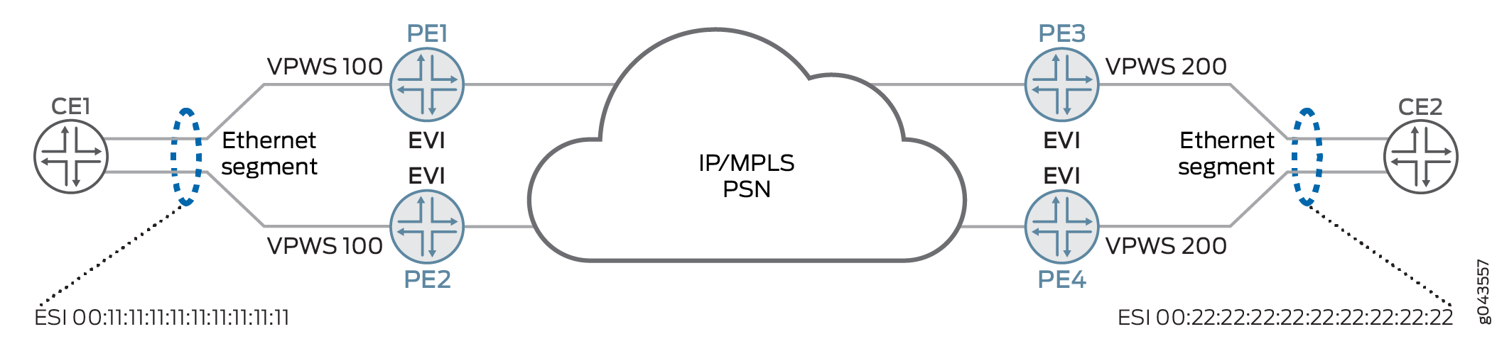
An Ethernet segment must have a unique nonzero identifier, called the Ethernet segment identifier (ESI). The ESI is encoded as a 10-octet integer. When manually configuring an ESI value, the most significant octet, known as the type byte, must be 00. When a single-homed CE device is attached to an Ethernet segment, the entire ESI value is zero. The Ethernet segment of the multihomed Device CE1 has an ESI value of 00:11:11:11:11:11:11:11:11:11 and the Ethernet segment of the multihomed Device CE2 has an ESI value of 00:22:22:22:22:22:22:22:22:22.
An EVPN instance (EVI) is an EVPN routing and forwarding instance spanning across all the PE routers participating in that VPN. An EVI is configured on the PE routers on a per-customer basis. Each EVI has a unique route distinguisher and one or more route targets. An EVI is configured on PE1, PE2, PE3, and PE4. An Ethernet tag identifies a particular broadcast domain, such as a VLAN. An EVI consists of one or more broadcast domains. Ethernet tags are assigned to the broadcast domains of a given EVI by the provider of that EVPN. Each PE router in that EVI performs a mapping between broadcast domain identifiers understood by each of its attached CE devices and the corresponding Ethernet tag. Depending on the multihoming mode of redundancy, only one path or all paths can be active at any one time.
The multihoming mode of operation along with VPWS service identifiers determine which PE router or routers forward and receive traffic in the EVPN-VPWS network. The VPWS service identifier identifies the endpoints of the EVPN-VPWS network. These endpoints are autodiscovered by BGP and are used to exchange the service labels(learned from the respective PE routers) that are used by autodiscovered routes per EVI route type. The service identifier is of two types:
-
Local— Unique local VPWS service identifier. This is a logical identifier mapped to a physical interface of a PE router connected to the customer site that is forwarding the traffic to a remote VPWS service identifier.
-
Remote—Unique remote VPWS service identifier. This is a logical identifier mapped to a physical interface of a PE router connected to the customer site that is receiving the traffic forwarded from the local VPWS service identifier.
The PE router forwarding traffic to the CE device uses MPLS LSP to forward traffic. If a failure occurs over this path, a new designated forwarder is elected to forward the traffic to the CE device.
The EVPN-VPWS network uses only an autodiscovered route per ESI and an autodiscovered router per EVI route types. In autodiscovered routes per EVI, the 24-bit values of the Ethernet tag are encoded with the VPWS service identifier. The autodiscovered route per ESI is encoded with the route targets of all the EVPN-VPWS instances connected to the ESI on the advertising PE router . When the PE router loses its connectivity to the ESI, it withdraws the autodiscovered route per ESI, resulting in faster convergence. The receiving PE router updates the forwarding next hop of the VPWS service identifier impacted by the failure. Depending on the mode of operation, these two endpoints of the EVPN-VPWS network can be colocated on the same PE router or on different PE routers. The different modes of operation in an EVPN-VPWS network are as follows:
-
Local switching—In this mode, the VPWS endpoints (that is, local and remote service identifiers) are connected through the local interfaces configured on the same PE router. Traffic from one CE router is forwarded to another CE router through the same PE router.
-
Single-homing–When a PE router is connected to a single-homed customer site, this mode is in operation.
-
Active-standby multihoming—In this mode, only a single PE router among a group of PE routers with the same VPWS service identifier attached to an Ethernet segment is allowed to forward traffic to and from that Ethernet segment. The process of electing one among many PE routers with the same VPWS service identifer is known as the designated forwarder (DF) election. Each PE router connected to the Ethernet segment with the same VPWS service identifier participates in the DF election and informs the network of its status. The status can be as follows:
-
Designated forwarder(DF)—This is the designated forwarder for forwarding the current traffic.
-
Backup designated forwarder(BDF)—This becomes the DF in case the current DF encounters a failure.
-
Non-designated forwarder(non-DF)—This is neither the DF nor the BDF. When more than two PE routers are part of an ESI redundancy group, then this PE router becomes a non-DF.
To configure the active-standby mode, include the ESI value and the
single-activestatement under the [edit interfaces] hierarchy level. Configure thelocaland theremoteVPWS service identifier under the [edit routing-instances vpws-routing-instance protocols evpn interface interface-name vpws-service-id] for each PE router connected to the Ethernet segment.In Figure 1, for the PE routers connected to Device CE1, Router PE1 is assumed to be the DF and PE2 is assumed to be the BDF for VPWS service identifier 100. For the PE routers connected to CE2, PE3 is assumed to be the DF and Router PE4 is assumed to be the BDF for VPWS service identifier 200. PE2 and PE4 indicate their BDF status to CE1 and CE2 by setting their circuit cross-connect (CCC)-Down flag on their respective interfaces.
-
-
Active-active multi-homing–In active-active multi homing, the CE device is connected to the PE routers with the same local VPWS identifier through the LAG interface so that the traffic is load-balanced among the set of multihomed PE routers with the same remote VPWS service identifiers. Here, election of DF is not required, because all the PE routers connected to the LAG interface participate in forwarding the traffic. In Figure 1, Device CE1 forwards traffic to PE1 and PE2 with VPWS service identifier 100 and CE2 forwards traffic to PE3 and PE4 with VPWS service identifier 200. PE1 forwards the traffic to PE3 and PE4 with remote VPWS service identifier 200. PE2 forwards the traffic to PE3 and PE4 . Similarly, traffic from CE2 to PE3 and PE4 with VPWS service identifier is load-balanced across PE routers with VPWS service identifier 100 connected to CE1.
Starting in cRPD Release 20.3R1, EVPN VPWS with EVPN Type 5 is supported to provide VPWS with EVPN signaling mechanisms on cRPD. VPWS with EVPN network is supported on single-homing.
NSR and Unified ISSU Support on VPWS with EVPN
Nonstop active routing (NSR) and graceful Routing Engine switchover (GRES) minimize traffic loss when there is a Routing Engine switchover. When a Routing Engine fails, NSR and GRES enable a routing platform with redundant Routing Engines to switch over from a primary Routing Engine to a backup Routing Engine and continue forwarding packets. Unified in-service software upgrade (ISSU) allows you to upgrade your Junos OS software on your MX Series router with no disruption on the control plane and with minimal disruption of traffic. Both GRES and NSR must be enabled to use unified ISSU.
To enable GRES, include the graceful-switchover statement
at the [edit chassis redundancy] hierarchy level.
To enable NSR, include the nonstop-routing statement
at the [edit routing-options] hierarchy level and the
commit synchronize statement at the [edit system] hierarchy level.
Change History Table
Feature support is determined by the platform and release you are using. Use Feature Explorer to determine if a feature is supported on your platform.