이 페이지 내용
OSPFv2 Sham 링크 구성
OSPFv2 Sham 링크 개요
두 PE(Provider Edge) 라우팅 디바이스 간에 영역 내 링크 또는 가짜 링크를 생성하여 VPN 백본이 백도어 링크보다 선호되도록 할 수 있습니다. 백도어 링크는 VPN 백본을 사용할 수 없는 경우 고객 에지(CE) 디바이스를 연결하는 백업 링크입니다. 이러한 백업 링크를 사용할 수 있고 CE 디바이스가 동일한 OSPF 영역에 있는 경우 기본 동작은 VPN 백본보다 이 백업 링크를 선호하는 것입니다. 이는 백업 링크가 영역 내 링크로 간주되는 반면 VPN 백본은 항상 영역 간 링크로 간주되기 때문입니다. 영역 내 링크는 항상 영역 간 링크보다 선호됩니다.
가짜 링크는 PE 장치 간에 번호가 지정되지 않은 포인트 투 포인트 영역 내 링크입니다. VPN 백본에 가짜 영역 내 링크가 있는 경우, 가짜 링크의 OSPF 메트릭이 백업 링크보다 낮으면 이 가짜 링크가 백업 링크보다 선호될 수 있습니다.
가짜 링크는 유형 1 LSA(Link-State Advertisements)를 사용하여 보급됩니다. Sham 링크는 라우팅 인스턴스 및 OSPFv2에만 유효합니다.
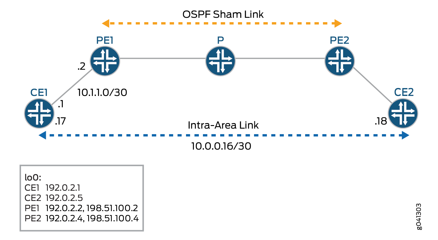
각 가짜 링크는 로컬 엔드포인트 주소와 원격 엔드포인트 주소의 조합으로 식별됩니다. 그림 1 은 OSPFv2 가짜 링크를 보여줍니다. 라우터 CE1 및 라우터 CE2는 동일한 OSPFv2 영역에 있습니다. 이러한 고객 에지(CE) 라우팅 디바이스는 라우터 PE1 및 라우터 PE2를 통해 레이어 3 VPN에 의해 함께 연결됩니다. 또한 라우터 CE1과 라우터 CE2는 백업으로 사용되는 영역 내 링크로 연결됩니다.
OSPFv2는 레이어 3 VPN을 통해 링크를 영역 간 링크로 처리합니다. 기본적으로 OSPFv2는 영역 간 링크보다 영역 내 링크를 선호하므로 OSPFv2는 백업 영역 내 링크를 활성 경로로 선택합니다. 영역 내 링크가 고객 에지(CE) 라우팅 디바이스 간 트래픽의 예상 기본 경로가 아닌 구성에서는 허용되지 않습니다. 가짜 링크에 대한 메트릭을 구성하여 레이어 3 VPN을 통한 경로가 고객 에지(CE) 라우팅 디바이스를 연결하는 영역 내 링크의 백업 경로보다 선호되도록 할 수 있습니다.
원격 엔드포인트의 경우 OSPFv2 인터페이스를 수요 회로로 구성하고, IPsec 인증을 구성하고(실제 IPsec 인증을 별도로 구성), 메트릭 값을 정의할 수 있습니다.
다음과 같은 경우 OSPFv2 가짜 링크를 구성해야 합니다.
고객 에지(CE) 라우팅 디바이스 2개는 레이어 3 VPN에 의해 서로 연결되어 있습니다.
이러한 CE 라우팅 디바이스는 동일한 OSPFv2 영역에 있습니다.
영역 내 링크는 두 개의 CE 라우팅 디바이스 간에 구성됩니다.
CE 라우팅 디바이스 간에 영역 내 링크가 없는 경우 OSPFv2 가짜 링크를 구성할 필요가 없습니다.
Junos OS 릴리스 9.6 이상에서는 OSPFv2 가짜 링크가 숨겨진 경로로 라우팅 테이블에 설치됩니다. 또한 해당 OSPF 가짜 링크를 사용할 수 있는 경우 BGP 경로를 OSPFv2로 내보내지 않습니다.
Junos OS 릴리스 16.1 이상에서는 OSPF sham-links가 기본 인스턴스에서 지원됩니다. 사용자가 sham-link에 메트릭을 구성하지 않은 경우 sham-link의 비용은 BGP 경로의 aigp-metric으로 동적으로 설정됩니다. aigp-metric이 BGP 경로에 없는 경우 sham-link 비용은 기본적으로 1로 설정됩니다.
예: OSPFv2 Sham 링크 구성
이 예는 PE 라우팅 디바이스에서 OSPFv2 가짜 링크를 활성화하는 방법을 보여줍니다.
요구 사항
이 예를 구성하기 전에 디바이스 초기화를 제외한 특별한 구성은 필요하지 않습니다.
개요
가짜 링크는 번호가 지정되지 않은 포인트 투 포인트 영역 내 링크이며 유형 1 LSA(Link-State Advertisement)를 통해 광고됩니다. Sham 링크는 라우팅 인스턴스 및 OSPFv2에만 유효합니다.
각 가짜 링크는 로컬 엔드포인트 주소와 원격 엔드포인트 주소 및 해당 링크가 속한 OSPFv2 영역의 조합으로 식별됩니다. 동일한 VPN 라우팅 및 포워딩(VRF) 라우팅 인스턴스 내에 있는 두 PE 디바이스 간에 sham 링크를 수동으로 구성하고 sham 링크의 로컬 엔드포인트에 대한 주소를 지정합니다. 이 주소는 가짜 링크 패킷의 소스로 사용되며, 가짜 링크 원격 엔드포인트로 원격 PE 라우팅 디바이스에서도 사용됩니다. 또한 옵션 metric 을(를) 포함하여 원격 엔드포인트에 대한 메트릭 값을 설정할 수도 있습니다. 메트릭 값은 링크 사용 비용을 지정합니다. 총 경로 메트릭이 낮은 경로는 경로 메트릭이 높은 경로보다 선호됩니다.
PE 라우팅 디바이스에서 OSPFv2 가짜 링크를 활성화하려면:
PE 라우팅 디바이스에서 추가 루프백 인터페이스를 구성합니다.
PE 라우팅 디바이스에서 레이어 3 VPN을 지원하는 VRF 라우팅 인스턴스를 구성하고 가짜 링크를 기존 최단 경로 우선(OSPF) 영역과 연결합니다. OSPFv2 가짜 링크 구성도 라우팅 인스턴스에 포함됩니다. 가짜 링크의 로컬 엔드포인트 주소(로컬 VPN의 루프백 주소)와 원격 엔드포인트 주소(원격 VPN의 루프백 주소)를 구성합니다. 이 예에서 VRF 라우팅 인스턴스의 이름은 red입니다.
그림 2 는 OSPFv2 가짜 링크를 보여줍니다.
구성
절차
CLI 빠른 구성
이 예를 빠르게 구성하려면, 아래 명령을 복사하여 텍스트 파일로 붙여 넣은 다음 모든 라인브레이크를 제거하고, 네트워크 구성을 일치하는 데 필요한 세부 사항을 바꾸고 계층 수준에서 명령을 CLI [edit] 로 복사해 붙여 넣습니다.
CE1
set interfaces fe-1/2/0 unit 0 family inet address 10.1.1.1/30
set interfaces fe-1/2/0 unit 0 family mpls
set interfaces fe-1/2/1 unit 0 family inet address 10.0.0.17/30
set interfaces lo0 unit 0 family inet address 192.0.2.1/24
set protocols ospf area 0.0.0.0 interface fe-1/2/0.0
set protocols ospf area 0.0.0.0 interface lo0.0 passive
set protocols ospf area 0.0.0.0 interface fe-1/2/1.0 metric 100
set policy-options policy-statement send-direct from protocol direct
set policy-options policy-statement send-direct then accept
set routing-options router-id 192.0.2.1
set routing-options autonomous-system 1
PE1
set interfaces fe-1/2/0 unit 0 family inet address 10.1.1.2/30
set interfaces fe-1/2/0 unit 0 family mpls
set interfaces fe-1/2/1 unit 0 family inet address 10.1.1.5/30
set interfaces fe-1/2/1 unit 0 family mpls
set interfaces lo0 unit 0 family inet address 192.0.2.2/24
set interfaces lo0 unit 1 family inet address 198.51.100.2/24
set protocols mpls interface fe-1/2/1.0
set protocols bgp group toR4 type internal
set protocols bgp group toR4 local-address 192.0.2.2
set protocols bgp group toR4 family inet-vpn unicast
set protocols bgp group toR4 neighbor 192.0.2.4
set protocols ospf area 0.0.0.0 interface fe-1/2/1.0
set protocols ospf area 0.0.0.0 interface lo0.0 passive
set protocols ldp interface fe-1/2/1.0
set protocols ldp interface lo0.0
set policy-options policy-statement bgp-to-ospf term 1 from protocol bgp
set policy-options policy-statement bgp-to-ospf term 1 then accept
set policy-options policy-statement bgp-to-ospf term 2 then reject
set routing-instances red instance-type vrf
set routing-instances red interface fe-1/2/0.0
set routing-instances red interface lo0.1
set routing-instances red route-distinguisher 2:1
set routing-instances red vrf-target target:2:1
set routing-instances red protocols ospf export bgp-to-ospf
set routing-instances red protocols ospf sham-link local 198.51.100.2
set routing-instances red protocols ospf area 0.0.0.0 sham-link-remote 198.51.100.4 metric 10
set routing-instances red protocols ospf area 0.0.0.0 interface fe-1/2/0.0
set routing-instances red protocols ospf area 0.0.0.0 interface lo0.1
set routing-options router-id 192.0.2.2
set routing-options autonomous-system 2
P
set interfaces fe-1/2/0 unit 0 family inet address 10.1.1.6/30
set interfaces fe-1/2/0 unit 0 family mpls
set interfaces fe-1/2/1 unit 0 family inet address 10.1.1.9/30
set interfaces fe-1/2/1 unit 0 family mpls
set interfaces lo0 unit 3 family inet address 192.0.2.3/24
set protocols mpls interface all
set protocols ospf area 0.0.0.0 interface lo0.3 passive
set protocols ospf area 0.0.0.0 interface all
set protocols ldp interface all
set routing-options router-id 192.0.2.3
PE2
set interfaces fe-1/2/0 unit 0 family inet address 10.1.1.10/30
set interfaces fe-1/2/0 unit 0 family mpls
set interfaces fe-1/2/1 unit 0 family inet address 10.1.1.13/30
set interfaces fe-1/2/1 unit 0 family mpls
set interfaces lo0 unit 0 family inet address 192.0.2.4/32
set interfaces lo0 unit 1 family inet address 198.51.100.4/32
set protocols mpls interface fe-1/2/0.0
set protocols bgp group toR2 type internal
set protocols bgp group toR2 local-address 192.0.2.4
set protocols bgp group toR2 family inet-vpn unicast
set protocols bgp group toR2 neighbor 192.0.2.2
set protocols ospf area 0.0.0.0 interface lo0.0 passive
set protocols ospf area 0.0.0.0 interface fe-1/2/0.0
set protocols ldp interface fe-1/2/0.0
set protocols ldp interface lo0.0
set policy-options policy-statement bgp-to-ospf term 1 from protocol bgp
set policy-options policy-statement bgp-to-ospf term 1 then accept
set policy-options policy-statement bgp-to-ospf term 2 then reject
set routing-instances red instance-type vrf
set routing-instances red interface fe-1/2/1.0
set routing-instances red interface lo0.1
set routing-instances red route-distinguisher 2:1
set routing-instances red vrf-target target:2:1
set routing-instances red protocols ospf export bgp-to-ospf
set routing-instances red protocols ospf sham-link local 198.51.100.4
set routing-instances red protocols ospf area 0.0.0.0 sham-link-remote 198.51.100.2 metric 10
set routing-instances red protocols ospf area 0.0.0.0 interface fe-1/2/1.0
set routing-instances red protocols ospf area 0.0.0.0 interface lo0.1
set routing-options router-id 192.0.2.4
set routing-options autonomous-system 2
CE2 (CE2)
set interfaces fe-1/2/0 unit 14 family inet address 10.1.1.14/30
set interfaces fe-1/2/0 unit 14 family mpls
set interfaces fe-1/2/0 unit 18 family inet address 10.0.0.18/30
set interfaces lo0 unit 5 family inet address 192.0.2.5/24
set protocols ospf area 0.0.0.0 interface fe-1/2/0.14
set protocols ospf area 0.0.0.0 interface lo0.5 passive
set protocols ospf area 0.0.0.0 interface fe-1/2/0.18
set policy-options policy-statement send-direct from protocol direct
set policy-options policy-statement send-direct then accept
set routing-options router-id 192.0.2.5
set routing-options autonomous-system 3
단계별 절차
다음 예제에서는 구성 계층에서 다양한 수준의 탐색이 필요합니다. CLI 탐색에 대한 정보는 CLI 사용자 가이드의 Junos OS 구성 수정을 참조하십시오.
각 PE 디바이스에서 OSPFv2 가짜 링크를 구성하려면 다음을 수행합니다.
-
두 개의 루프백 인터페이스를 포함하여 인터페이스를 구성합니다.
[edit interfaces]
user@PE1# set fe-1/2/0 unit 0 family inet address 10.1.1.2/30
user@PE1# set fe-1/2/0 unit 0 family mpls
user@PE1# set fe-1/2/1 unit 0 family inet address 10.1.1.5/30
user@PE1# set fe-1/2/1 unit 0 family mpls
user@PE1# set lo0 unit 0 family inet address 192.0.2.2/24
user@PE1# set lo0 unit 1 family inet address 198.51.100.2/24
-
코어 대면 인터페이스에서 MPLS를 구성합니다.
[edit protocols mpls]
user@PE1# set interface fe-1/2/1.0
-
내부 BGP(IBGP)를 구성합니다.
[edit ]
user@PE1# set protocols bgp group toR4 type internal
user@PE1# set protocols bgp group toR4 local-address 192.0.2.2
user@PE1# set protocols bgp group toR4 family inet-vpn unicast
user@PE1# set protocols bgp group toR4 neighbor 192.0.2.4
-
코어 대면 인터페이스와 기본 인스턴스에서 사용 중인 루프백 인터페이스에서 최단 경로 우선(OSPF)을 구성합니다.
[edit protocols ospf area 0.0.0.0]
user@PE1# set interface fe-1/2/1.0
user@PE1# set interface lo0.0 passive
-
코어 대면 인터페이스와 기본 인스턴스에서 사용되는 루프백 인터페이스에서 LDP 또는 RSVP를 구성합니다.
[edit protocols ldp]
user@PE1# set interface fe-1/2/1.0
user@PE1# set interface lo0.0
-
라우팅 인스턴스에서 사용할 라우팅 정책을 구성합니다.
[edit policy-options policy-statement bgp-to-ospf]
user@PE1# set term 1 from protocol bgp
user@PE1# set term 1 then accept
user@PE1# set term 2 then reject
-
라우팅 인스턴스를 구성합니다.
[edit routing-instances red]
user@PE1# set instance-type vrf
user@PE1# set interface fe-1/2/0.0
user@PE1# set route-distinguisher 2:1
user@PE1# set vrf-target target:2:1
user@PE1# set protocols ospf export bgp-to-ospf
user@PE1# set protocols ospf area 0.0.0.0 interface fe-1/2/0.0
-
OSPFv2 sham 링크를 구성합니다.
라우팅 인스턴스 및 OSPF 구성에 추가 루프백 인터페이스를 포함합니다.
sham-link 인터페이스의 메트릭은 10으로 설정됩니다. 디바이스 CE1의 백업 OSPF 링크에서 메트릭은 100으로 설정됩니다. 이렇게 하면 가짜 링크가 기본 링크가 됩니다.
[edit routing-instances red]
user@PE1# set interface lo0.1
user@PE1# set protocols ospf sham-link local 198.51.100.2
user@PE1# set protocols ospf area 0.0.0.0 sham-link-remote 198.51.100.4 metric 10
user@PE1# set protocols ospf area 0.0.0.0 interface lo0.1
-
AS(Autonomous System) 번호와 라우터 ID를 구성합니다.
[edit routing-options]
user@PE1# set router-id 192.0.2.2
user@PE1# set autonomous-system 2
-
디바이스 구성을 완료하면 해당 구성을 커밋합니다.
[edit]
user@R1# commit
결과
및 show routing-instances 명령을 입력하여 show interfaces 구성을 확인합니다. 출력 결과가 의도한 구성대로 표시되지 않으면 이 예의 지침을 반복하여 구성을 수정하십시오.
PE1의 출력:
user@PE1# show interfaces
fe-1/2/0 {
    unit 0{
        family inet {
            address 10.1.1.2/30;
        }
        family mpls;
    }
}
fe-1/2/1 {
    unit 0 {
        family inet {
            address 10.1.1.5/30;
        }
        family mpls;
    }
}
lo0 {
    unit 0 {
        family inet {
            address 192.0.2.2/24;
        }
    }
    unit 1 {
        family inet {
            address 198.51.100.2/24;
        }
    }
}
user@PE1# show protocols
mpls {
    interface fe-1/2/1.0;
}
bgp {
    group toR4 {
        type internal;
        local-address 192.0.2.2;
        family inet-vpn {
            unicast;
        }
        neighbor 192.0.2.4;
    }
}
ospf {
    area 0.0.0.0 {
        interface fe-1/2/1.0;
        interface lo0.0 {
            passive;
        }
    }
}
ldp {
    interface fe-1/2/1.0;
    interface lo0.0;
}
user@PE1# show policy-options
policy-statement bgp-to-ospf {
    term 1 {
        from protocol bgp;
        then accept;
    }
    term 2 {
        then reject;
    }
}
user@PE1# show routing-instances
red {
    instance-type vrf;
    interface fe-1/2/0.0;
    interface lo0.1;
    route-distinguisher 2:1;
    vrf-target target:2:1;
    protocols {
        ospf {
            export bgp-to-ospf;
            sham-link local 198.51.100.2;
            area 0.0.0.0 {
                sham-link-remote 198.51.100.4 metric 10;
                interface fe-1/2/0.0;
                interface lo0.1;
            }
        }
    }
}
user@PE1# show routing-options
router-id 192.0.2.2;
autonomous-system 2;
확인
구성이 올바르게 작동하고 있는지 확인합니다.
Sham 링크 인터페이스 확인
목적
가짜 링크 인터페이스를 확인합니다. 가짜 링크는 OSPFv2에서 인터페이스로 처리되며, 이름은 (으)로 shamlink.<unique identifier>표시됩니다. 여기서 고유 식별자는 숫자입니다. 예를 들어, shamlink.0. 가짜 링크는 포인트 투 포인트 인터페이스로 나타납니다.
행동
운영 모드에서 명령을 입력합니다 show ospf interface instance instance-name .
user@PE1> show ospf interface instance red
Interface           State   Area            DR ID           BDR ID          Nbrs
lo0.1              DR      0.0.0.0         198.51.100.2         0.0.0.0            0
fe-1/2/0.0          PtToPt  0.0.0.0         0.0.0.0         0.0.0.0            1
shamlink.0          PtToPt  0.0.0.0         0.0.0.0         0.0.0.0            1
Sham 링크의 로컬 및 원격 엔드포인트 확인
목적
가짜 링크의 로컬 및 원격 엔드포인트를 확인합니다. 가짜 링크 인터페이스의 MTU는 항상 0입니다.
행동
운영 모드에서 명령을 입력합니다 show ospf interface instance instance-name detail .
user@PE1> show ospf interface shamlink.0 instance red
Interface           State   Area            DR ID           BDR ID          Nbrs
shamlink.0          PtToPt  0.0.0.0         0.0.0.0         0.0.0.0            1
  Type: P2P, Address: 0.0.0.0, Mask: 0.0.0.0, MTU: 0, Cost: 10
  Local: 198.51.100.2, Remote: 198.51.100.4
  Adj count: 1
  Hello: 10, Dead: 40, ReXmit: 5, Not Stub
  Auth type: None
  Protection type: None, No eligible backup
  Topology default (ID 0) -> Cost: 10
Sham 링크 인접성 확인
목적
구성된 가짜 링크 간의 인접성을 확인합니다.
행동
운영 모드에서 명령을 입력합니다 show ospf neighbor instance instance-name .
user@PE1> show ospf neighbor instance red
Address          Interface              State     ID               Pri  Dead
10.1.1.1         fe-1/2/0.0             Full      192.0.2.1          128    35
198.51.100.4          shamlink.0             Full      198.51.100.4            0    31
Link-State 광고 확인
목적
인스턴스에 의해 시작된 라우터 LSA가 번호가 지정되지 않은 점대점(point-to-point) 링크로 가짜 링크 인접성을 전달하는지 확인합니다. 가짜 링크의 링크 데이터는 0x80010000에서 0x8001ffff까지의 숫자입니다.
행동
운영 모드에서 명령을 입력합니다 show ospf database instance instance-name .
user@PE1> show ospf database instance red

    OSPF database, Area 0.0.0.0
 Type       ID               Adv Rtr           Seq      Age  Opt  Cksum  Len
Router   192.0.2.1          192.0.2.1          0x80000009  1803  0x22 0x6ec7  72
Router   192.0.2.5          192.0.2.5          0x80000007    70  0x22 0x2746  72
Router  *198.51.100.2          198.51.100.2          0x80000006    55  0x22 0xda6b  60
Router   198.51.100.4          198.51.100.4          0x80000005    63  0x22 0xb19   60
Network  10.0.0.18        192.0.2.5          0x80000002    70  0x22 0x9a71  32
    OSPF AS SCOPE link state database
 Type       ID               Adv Rtr           Seq      Age  Opt  Cksum  Len
Extern   198.51.100.2          198.51.100.4          0x80000002    72  0xa2 0x343   36
Extern  *198.51.100.4          198.51.100.2          0x80000002    71  0xa2 0xe263  36
경로 선택 확인
목적
백업 경로 대신 레이어 3 VPN 경로가 사용되는지 확인합니다.
행동
운영 모드에서 디바이스 CE1에서 디바이스 CE2로 명령을 입력합니다 traceroute .
user@CE1> traceroute 192.0.2.5

traceroute to 192.0.2.5 (192.0.2.5), 30 hops max, 40 byte packets
 1  10.1.1.2 (10.1.1.2)  1.930 ms  1.664 ms  1.643 ms
 2  * * *
 3  10.1.1.10 (10.1.1.10)  2.485 ms  1.435 ms  1.422 ms
     MPLS Label=299808 CoS=0 TTL=1 S=1
 4  192.0.2.5 (192.0.2.5)  1.347 ms  1.362 ms  1.329 ms
의미
트레이스라우트 작업은 레이어 3 VPN이 선호되는 경로임을 보여줍니다. 가짜 링크를 제거하거나 해당 백업 경로를 선호하도록 OSPF 메트릭을 수정하려는 경우 traceroute는 백업 경로가 선호되는 것으로 표시됩니다.