멀티프로토콜 BGP 멀티캐스트 VPN 구성
멀티프로토콜 BGP 기반 멀티캐스트 VPN 이해하기: 차세대
멀티프로토콜 BGP 기반 멀티캐스트 VPN(차세대 레이어 3 VPN 멀티캐스트라고도 함)은 듀얼 멀티캐스트 VPN(draft-rosen)에 이어 차세대 진화를 구성하며, 레이어 3 VPN을 통해 멀티캐스트를 구성하려는 관리자에게 보다 간단한 솔루션을 제공합니다.
멀티프로토콜 BGP 기반 멀티캐스트 VPN의 주요 특징은 다음과 같습니다.
레이어 3 VPN 서비스(RFC 2547)를 확장하여 레이어 3 VPN 서비스 프로바이더에 대한 IP 멀티캐스트를 지원합니다.
유니캐스트 VPN에 대해 RFC 2547에서 지정한 것과 동일한 아키텍처를 따릅니다. 특히 BGP는 컨트롤 플레인으로 사용됩니다.
멀티캐스트 VPN에 대한 인터넷 초안 draft-rosen-vpn-mcast, MPLS/BGP VPN의 멀티캐스트에 지정된 VR(가상 라우터) 모델에 대한 요구 사항을 제거합니다.
이들은 AS 내 및 AS 간 통신을 위한 확장이 있는 RFC 기반 유니캐스트에 의존합니다.
멀티프로토콜 BGP 기반 VPN은 발신자 세트와 수신자 세트라는 두 개의 사이트 세트로 정의됩니다. 수신자 사이트 집합 내의 호스트는 멀티캐스트 트래픽을 수신할 수 있고 발신자 사이트 집합 내의 호스트는 멀티캐스트 트래픽을 보낼 수 있습니다. 사이트 집합은 수신자와 발신자가 될 수 있으며, 이는 이러한 사이트 내의 호스트가 멀티캐스트 트래픽을 보내고 받을 수 있음을 의미합니다. 멀티프로토콜 BGP 기반 VPN은 조직을 확장하고(사이트가 인트라넷 또는 엑스트라넷이 될 수 있음), 서비스 프로바이더를 확장하고, 중첩될 수 있습니다.
사이트 관리자는 고객 요구 사항과 기존 BGP 및 MPLS VPN 인프라에 따라 멀티프로토콜 BGP 기반 VPN을 구성합니다.
MVPN의 경로 리플렉터 동작
BGP 기반 MVPN(Multicast VPN) 고객 멀티캐스트 경로는 경로 리플렉터에 의해 어그리게이션됩니다. RR(Route Reflector)은 둘 이상의 PE(Provider Edge) 라우터에서 동일한 NLRI를 사용하는 고객 멀티캐스트 경로를 수신할 수 있지만 RR은 이러한 NLRI를 하나만 재보급합니다. 이 NLRI를 보급하는 PE 라우터 집합이 변경되면 RR은 경로를 업데이트하지 않습니다. 이를 통해 경로 변동을 최소화할 수 있습니다. 이를 위해 RR은 다음 홉을 self로 설정합니다. 또한 RR은 발신자 ID를 자신으로 설정합니다. RR은 RR이 이미 보급하고 있는 NLRI에 대한 후속 고객 멀티캐스트 경로를 수신할 경우 불필요한 최적 경로 계산을 방지합니다. 이를 통해 동일한 MVPN NLRI로 소스 활성 및 고객 멀티캐스트 경로를 어그리게이션할 수 있습니다.
또한보십시오
예: AS 내 MBGP MVPN을 위한 데이터 플레인으로 Point-to-Multipoint LDP LSP 구성
이 예는 P2MP(Point-to-multipoint) LDP LSP(Label-Switched Paths)를 AS(Intra-Autonomous System) 멀티프로토콜 BGP(MBGP) 멀티캐스트 VPN(MVPN)의 데이터 플레인으로 구성하는 방법을 보여줍니다. 이 기능은 MPLS 백본에서 이미 LDP를 실행 중이고 MBGP MVPN 기능이 필요한 서비스 프로바이더에게 적합합니다.
요구 사항
시작하기 전에:
라우터 인터페이스를 구성합니다. 라우팅 디바이스용 Junos OS 네트워크 인터페이스 라이브러리를 참조하십시오.
내부 게이트웨이 프로토콜 또는 정적 라우팅을 구성합니다. 라우팅 디바이스용 Junos OS 라우팅 프로토콜 라이브러리를 참조하십시오.
BGP-MVPN 컨트롤 플레인을 구성합니다. 멀티캐스트 프로토콜 사용 설명서의 MBGP 기반 멀티캐스트 VPN 트리를 참조하십시오.
모든 P2MP 프로바이더 및 프로바이더-에지 라우터에서 LDP를 신호 프로토콜로 구성합니다. Junos OS MPLS 애플리케이션 사용자 가이드의 LDP 작업을 참조하십시오.
발신자 사이트 집합에 속하는 MVPN의 각 PE 라우터에서 P2MP LDP LSP를 프로바이더 터널 기술로 구성합니다. Junos OS MPLS 애플리케이션 사용자 가이드를 참조하십시오.
가상 루프백 터널 인터페이스(터널 PIC 필요) 또는
vrf-table-labelMVPN 라우팅 인스턴스의 문을 구성합니다. 명령문을 구성vrf-table-label하면 선택적 가상 루프백 터널 인터페이스도 구성할 수 있습니다.엑스트라넷 시나리오에서 송신 PE 라우터가 특정 멀티캐스트 스트림을 수신해야 하는 여러 MVPN 인스턴스에 속할 경우, 송신 PE 라우터에 가상 루프백 터널 인터페이스(및 터널 PIC)가 필요합니다. 라우팅 디바이스용 Junos OS 서비스 인터페이스 라이브러리의 VRF 테이블 조회를 위한 가상 루프백 터널 구성을 참조하십시오.
송신 PE 라우터가 Point-to-Multipoint LSP의 전송 라우터이기도 한 경우, 송신 PE 라우터에 가상 루프백 터널 인터페이스(및 터널 PIC)가 필요합니다. 멀티캐스트 프로토콜 사용자 가이드의 VRF 테이블 조회를 위한 가상 루프백 터널 구성을 참조하십시오.
포인트 투 멀티캐스트 LDP LSP를 데이터 플레인으로 사용하는 MBGP MVPN의 일부 엑스트라넷 구성에는 송신 PE 라우터에 가상 루프백 터널 인터페이스(및 터널 PIC)가 필요합니다. 송신 PE 라우터가 특정 멀티캐스트 스트림을 수신해야 하는 여러 MVPN 인스턴스에 속해 있는 경우,
vrf-table-table문을 사용할 수 없습니다. 그림 1에서 CE1 및 CE2 라우터는 서로 다른 MVPN에 속합니다. 그러나 Source에서 보내는 멀티캐스트 스트림을 수신하려고 합니다. 라우터 PE2에서vrf-table-label명령문이 구성된 경우 패킷을 CE1 및 CE2 모두로 전달할 수 없습니다. 이로 인해 패킷 손실이 발생합니다. 가상 루프백 터널 인터페이스가 라우터 PE2의 두 MVPN 라우팅 인스턴스에서 사용되는 경우 패킷은 라우터 CE1과 CE2 모두로 전달됩니다. 따라서 송신 PE 라우터가 특정 멀티캐스트 스트림을 수신하는 여러 MVPN 인스턴스에 속하는 엑스트라넷 시나리오를 사용하거나 송신 PE 라우터를 point-to-multipoint LSP의 전송 라우터로 사용하는 경우 가상 루프백 터널 인터페이스를 설정해야 합니다.메모:Junos OS 릴리스 15.1X49-D50 및 Junos OS 릴리스 17.3R1부터 문은
vrf-table-label내부 레이블을 특정 VRF(Virtual Routing and Forwarding)에 매핑할 수 있습니다. 이 매핑을 사용하면 송신 VPN 라우터에서 캡슐화된 IP 헤더를 검사할 수 있습니다. SRX 시리즈 방화벽의vrf-table-label경우, 문은 현재 물리적 인터페이스에서만 지원됩니다. 해결 방법으로 물리적 인터페이스를 비활성화vrf-table-label하거나 사용합니다.그림 1: P2MP LDP LSP를 데이터 플레인으로 사용하는 MBGP MVPN의 엑스트라넷 구성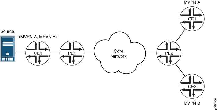
자세한 내용은 VRF 테이블 조회를 위한 가상 루프백 터널 구성을 참조하십시오 .
개요
이 주제에서는 P2MP LDP LSP를 AS 내 선택적 공급자 터널의 데이터 플레인으로 구성하는 방법에 대해 설명합니다. 선택적 P2MP LSP는 특정 고객의 멀티캐스트 스트림의 대역폭 임계값에 의해서만 트리거됩니다. PE 라우터에 의해 지정된 고객 소스 및 고객 그룹 쌍(C-S, C-G)에 대해 별도의 P2MP LDP LSP가 설정됩니다. C-S는 발신자 사이트 집합에 속하는 PE 라우터 뒤에 있습니다. MVPN에서 AS 내 선택적 프로바이더 터널의 어그리게이션은 지원되지 않습니다.
선택적 프로바이더 터널을 구성할 때 리프는 다음과 같이 P2MP LSP 루트를 발견합니다. 고객 멀티캐스트 스트림용 수신기가 뒤에 있는 PE 라우터는 그 뒤에 고객 멀티캐스트 스트림의 소스와 함께 PE 라우터의 ID(및 프로바이더 터널 정보)를 검색해야 합니다. 이 정보는 C-S가 뒤에 있는 PE 라우터에 의해 시작된 S-PMSI AD 경로를 사용하여 동적으로 자동 검색됩니다.
또한 Junos OS는 AS 내 포함 프로바이더 터널의 데이터 플레인으로 P2MP LDP LSP를 지원합니다. 이러한 터널은 MVPN 구성에 따라 트리거됩니다. 발신자 사이트 집합에 속하는 PE 라우터에 의해 지정된 MVPN에 대해 별도의 P2MP LSP LSP가 설정됩니다. 이 PE 라우터는 P2MP LSP의 루트입니다. MVPN에서 AS 내 포함 프로바이더 터널의 어그리게이션은 지원되지 않습니다.
포괄적 프로바이더 터널을 구성할 때, 리프는 다음과 같이 P2MP LSP 루트를 발견합니다. 특정 MVPN에 대한 수신자 사이트가 있는 PE 라우터는 해당 MVPN에 대한 발신자 사이트와 함께 PE 라우터의 ID(및 프로바이더 터널 정보)를 검색해야 합니다. 이 정보는 발신자 사이트가 있는 PE 라우터에서 시작된 AS 내 자동 검색 경로를 사용하여 동적으로 자동 검색됩니다.
위상수학
그림 2 는 이 예에서 사용된 토폴로지를 보여줍니다.
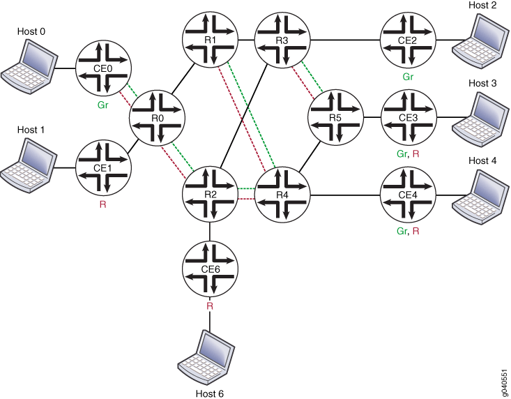
그림 2에서 라우터는 다음과 같은 기능을 수행합니다.
R1 및 R2는 프로바이더(P) 라우터입니다.
R0, R3, R4 및 R5는 프로바이더 에지(PE) 라우터입니다.
MBGP MVPN은 모든 PE 라우터에서 구성됩니다.
녹색과 빨간색의 두 가지 VPN이 정의됩니다.
라우터 R0은 별도의 라우팅 인스턴스에서 녹색 및 빨간색 CE 라우터를 모두 제공합니다.
라우터 R3은 녹색 CE 라우터에 연결됩니다.
라우터 R5는 단일 라우팅 인스턴스에서 중복 녹색 및 빨간색 CE 라우터에 연결됩니다.
라우터 R4는 단일 라우팅 인스턴스에서 중첩되는 녹색 및 빨간색 CE 라우터에 연결됩니다.
OSPF 및 멀티포인트 LDP(mLDP)가 코어에서 실행되고 있습니다.
라우터 R1은 경로 리플렉터(RR)이고 라우터 R2는 중복 RR입니다.
라우터 R0, R3, R4 및 R5는 클라이언트 내부 BGP(IBGP) 피어입니다.
구성
CLI 빠른 구성
이 예를 빠르게 구성하려면, 아래 명령을 복사하여 텍스트 파일로 붙여 넣은 다음 모든 라인브레이크를 제거하고, 네트워크 구성을 일치하는 데 필요한 세부 사항을 변경한 다음, 계층 수준에서 명령을 CLI로 [edit] 복사해 붙여 넣습니다.
set protocols ldp interface fe-0/2/1.0
set protocols ldp interface fe-0/2/3.0
set protocols ldp p2mp
set routing-instance red instance-type vrf
set routing-instance red interface vt-0/1/0.1
set routing-instance red interface lo0.1
set routing-instance red  route-distinguisher 10.254.1.1:1
set routing-instance red provider-tunnel ldp-p2mp
set routing-instance red provider-tunnel selective group 224.1.1.1/32 source 192.168.1.1/32 ldp-p2mp
절차
단계별 절차
다음 예제에서는 구성 계층의 다양한 수준을 탐색해야 합니다. CLI 탐색에 대한 자세한 내용은 Junos OS CLI 사용자 가이드의 구성 모드에서 CLI 편집기 사용을 참조하십시오.
P2MP LDP LSP를 AS 내 MBGP MVPN의 데이터 플레인으로 구성하려면,
모든 라우터에서 LDP를 구성합니다.
[edit protocols ldp]
user@host# set interface fe-0/2/1.0
user@host# set interface fe-0/2/3.0
user@host# set p2mp
프로바이더 터널을 구성합니다.
[edit routing-instance red ]
user@host# set instance-type vrf
user@host# set interface vt-0/1/0.1
user@host# set interface lo0.1
user@host# set route-distinguisher 10.254.1.1:1
user@host# set provider-tunnel ldp-p2mp
선택적 제공자 터널을 구성합니다.
user@host# set provider-tunnel selective group 224.1.1.1/32 source 192.168.1.1/32 ldp-p2mp
디바이스 구성을 완료하면 구성을 커밋합니다.
user@host# commit
결과
구성 모드에서 및 show routing-intances 명령을 입력하여 show protocols 구성을 확인합니다. 출력이 의도한 구성을 표시하지 않으면, 이 예의 구성 지침을 반복하여 수정합니다.
user@host# show protocols
ldp {
    interface fe-0/2/1.0;
    interface fe-0/2/3.0;
    p2mp;
}
user@host# show routing-instances
red {
    instance-type vrf;
    interface vt-0/1/0.1;
    interface lo0.1;
    route-distinguisher 10.254.1.1:1;
    provider-tunnel {
        ldp-p2mp;
    }
    selective {
        group 224.1.1.1/32 {
            source 192.168.1.1/32 {
                ldp-p2mp;
            }
        }
    }
    }
}
확인
구성을 확인하려면 다음 명령을 실행합니다.
mpls ldp p2mp를 ping 하여 P2MP LSP의 엔드포인트를 ping합니다.
show ldp database 를 사용하여 LDP P2MP 레이블 바인딩을 표시하고 LDP P2MP LSP가 신호를 받도록 합니다.
show ldp session detail - 피어와 교환되는 LDP 기능을 표시합니다. 보급된 기능 및 수신된 기능 필드에는 p2mp가 포함되어야 합니다.
show ldp traffic-statistics p2mp - P2MP LSP에 대한 데이터 트래픽 통계를 표시합니다.
멀티캐스트 VPN 라우팅 인스턴스 정보를 표시하고 LDP P2MP LSP가 S-PMSI로 MVPN과 연결되었는지 확인하기 위해 show mvpn instance, show mvpn neighbor 및 show mvpn c-multicast를 표시합니다.
PE 라우터에 멀티캐스트 경로 인스턴스 세부 정보를 표시하여 모든 호스트가 트래픽을 수신하도록 하고 수신기에 통계를 표시합니다.
show route label label detail : 레이블이 LDP P2MP LSP에 대한 입력 레이블인 경우 P2MP FEC(Forwarding Equivalence Class)를 표시합니다.
예: MBGP MVPN을 사용하여 IP 멀티캐스트를 위한 수신 복제 구성
요구 사항
이 예에서 사용되는 라우터는 주니퍼 네트웍스 M 시리즈 멀티서비스 에지 라우터, T 시리즈 코어 라우터 또는 MX 시리즈 5G 유니버설 라우팅 플랫폼입니다. IP 멀티캐스트에 수신 복제를 사용할 때, 각 참여 라우터는 컨트롤 플레인 절차를 위한 BGP와 MPLS 포인트 투 포인트 LSP의 풀 메시를 형성하는 데이터 공급자 터널에 대한 수신 복제로 구성되어야 합니다. 수신 복제 터널은 라우팅 인스턴스의 프로바이더 터널 구성에 따라 선택적이거나 포괄적일 수 있습니다.
개요
ingress-replication 프로바이더 터널 유형은 라우터 간의 유니캐스트 터널을 사용하여 멀티캐스트 배포 트리를 생성합니다.
mpls-internet-multicast 라우팅 인스턴스 유형은 수신 복제 공급자 터널을 사용하여 MBGP(또는 차세대) MVPN을 사용하여 MPLS 클라우드를 통해 라우터 간에 IP 멀티캐스트 데이터를 전송합니다. 또한 MVPN을 사용하여 PE 라우터 간에 멀티캐스트 데이터를 전송할 때 수신 복제를 구성할 수 있습니다.
mpls-internet-multicast 라우팅 인스턴스는 컨트롤 플레인 절차에만 사용되는 비포워딩 인스턴스입니다. 인터페이스 구성은 지원하지 않습니다. 논리적 시스템에 대해 하나의 mpls-internet-multicast 라우팅 인스턴스만 정의할 수 있습니다. IP 멀티캐스트에 사용되는 모든 멀티캐스트 및 유니캐스트 경로는 구성된 라우팅 인스턴스가 아닌 기본 라우팅 인스턴스(inet.0)에만 연결됩니다. mpls-internet-multicast 라우팅 인스턴스 유형은 각 라우터의 기본 마스터 인스턴스에 대해 구성되며 기본 인스턴스의 계층 수준에도 포함됩니다[edit protocols pim].
각 mpls-internet-multicast 라우팅 인스턴스에 ingress-replication 대해 문은 문과 계층 수준 아래에 provider-tunnel [edit routing-instances routing-instance-name provider-tunnel selective group source] 필요합니다.
수신 복제 제공자 터널에 새 대상을 추가해야 하는 경우 수신 복제 제공자 터널이 구성된 방식에 따라 결과 동작이 달라집니다.
create-new-ucast-tunnel- 이 명령문이 구성되면 대상에 대한 새로운 유니캐스트 터널이 생성되고 대상이 더 이상 필요하지 않을 때 삭제됩니다. 수신 복제를 사용하는 RSVP LSP에 이 모드를 사용합니다.label-switched-path-template (Multicast)—이 문이 구성되면 수신 복제를 위한 point-to-multipoint LSP에 LSP 템플릿이 사용됩니다.
위상수학
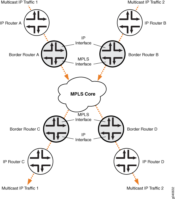
IP 토폴로지는 IP 멀티캐스트 도메인의 에지에 있는 라우터로 구성됩니다. 각 라우터에는 MPLS 클라우드를 향해 구성된 IP 인터페이스 집합과 IP 라우터를 향해 구성된 인터페이스 집합이 있습니다. 그림 3을 참조하십시오. 인터넷 멀티캐스트 트래픽은 데이터 플레인용 수신 복제 터널과 컨트롤 플레인용 풀 메시 IBGP 세션을 사용하여 MPLS 클라우드를 통해 IP 라우터 간에 전송됩니다.
구성
절차
CLI 빠른 구성
이 예를 빠르게 구성하려면, 아래 명령을 복사하여 텍스트 파일로 붙여 넣은 다음 모든 라인브레이크를 제거하고, 네트워크 구성을 일치하는 데 필요한 세부 사항을 변경한 다음, 계층 수준에서 명령을 CLI로 [edit] 복사해 붙여 넣습니다.
경계 라우터 C
set protocols mpls ipv6-tunneling
set protocols mpls interface all
set protocols bgp group ibgp type internal
set protocols bgp group ibgp local-address 10.255.10.61
set protocols bgp group ibgp family inet unicast
set protocols bgp group ibgp family inet-vpn any
set protocols bgp group ibgp family inet6 unicast
set protocols bgp group ibgp family inet6-vpn any
set protocols bgp group ibgp family inet-mvpn signaling
set protocols bgp group ibgp family inet6-mvpn signaling
set protocols bgp group ibgp export to-bgp
set protocols bgp group ibgp neighbor 10.255.10.97
set protocols bgp group ibgp neighbor 10.255.10.55
set protocols bgp group ibgp neighbor 10.255.10.57
set protocols bgp group ibgp neighbor 10.255.10.59
set protocols ospf traffic-engineering
set protocols ospf area 0.0.0.0 interface fxp0.0 disable
set protocols ospf area 0.0.0.0 interface lo0.0
set protocols ospf area 0.0.0.0 interface so-1/3/1.0
set protocols ospf area 0.0.0.0 interface so-0/3/0.0
set protocols ospf3 area 0.0.0.0 interface lo0.0
set protocols ospf3 area 0.0.0.0 interface so-1/3/1.0
set protocols ospf3 area 0.0.0.0 interface so-0/3/0.0
set protocols ldp interface all
set protocols pim rp static address 192.0.2.2
set protocols pim rp static address 2::192.0.2.2
set protocols pim interface fe-0/1/0.0
set protocols pim mpls-internet-multicast
set routing-instances test instance-type mpls-internet-multicast
set routing-instances test provider-tunnel ingress-replication label-switched-path
set routing-instances test protocols mvpn
단계별 절차
다음 예제에서는 구성 계층의 다양한 수준을 탐색해야 합니다. CLI 탐색에 대한 정보는 CLI 사용자 가이드의 구성 모드에서 CLI 편집기 사용을 참조하십시오.
다음 예에서는 라우팅 인스턴스 유형이 mpls-internet-multicast인 IP 멀티캐스트 인스턴스에서 수신 복제를 구성하는 방법을 보여 줍니다. 또한 이 예에서는 멀티캐스트 배포 트리에 새 대상을 추가해야 할 때마다 새 유니캐스트 터널을 선택하는 선택적 프로바이더 터널을 구성하는 방법을 보여줍니다.
이 예에서는 경계 라우터 C와 경계 라우터 C가 PIM 조인 메시지를 수신하는 경계 IP 라우터 C 간의 링크 구성을 보여 줍니다.
MPLS를 활성화합니다.
[edit protocols mpls]
user@Border_Router_C# set ipv6-tunneling
user@Border_Router_C# set interface all
RSVP 또는 LDP와 같은 신호 프로토콜을 구성합니다.
[edit protocols ldp]
user@Border_Router_C# set interface all
IBGP 피어링 세션의 풀 메시를 구성합니다.
[edit protocols bgp group ibgp]
user@Border_Router_C# set type internal
user@Border_Router_C# set local-address 10.255.10.61
user@Border_Router_C# set neighbor 10.255.10.97
user@Border_Router_C# set neighbor 10.255.10.55
user@Border_Router_C# set neighbor 10.255.10.57
user@Border_Router_C# set neighbor 10.255.10.59
user@Border_Router_C# set export to-bgp
BGP 세션이 필요한 NLRI를 전달하도록 멀티프로토콜 BGP 관련 설정을 구성합니다.
[edit protocols bgp group ibgp]
user@Border_Router_C# set family inet unicast
user@Border_Router_C# set family inet-vpn any
user@Border_Router_C# set family inet6 unicast
user@Border_Router_C# set family inet6-vpn any
user@Border_Router_C# set family inet-mvpn signaling
user@Border_Router_C# set family inet6-mvpn signaling
내부 게이트웨이 프로토콜(IGP)을 구성합니다.
이 예에서는 인터페이스에 OSPF 및 OSPF 버전 3이 구성된 이중 스택 구성을 보여 줍니다.
[edit protocols ospf3]
user@Border_Router_C# set area 0.0.0.0 interface lo0.0
user@Border_Router_C# set area 0.0.0.0 interface so-1/3/1.0
user@Border_Router_C# set area 0.0.0.0 interface so-0/3/0.0
[edit protocols ospf]
user@Border_Router_C# set traffic-engineering
user@Border_Router_C# set area 0.0.0.0 interface fxp0.0 disable
user@Border_Router_C# set area 0.0.0.0 interface lo0.0
user@Border_Router_C# set area 0.0.0.0 interface so-1/3/1.0
user@Border_Router_C# set area 0.0.0.0 interface so-0/3/0.0
에지 디바이스를 향하는 인터페이스에 글로벌 PIM 인스턴스를 구성합니다.
PIM은 코어에서 구성되지 않습니다.
[edit protocols pim]
user@Border_Router_C# set rp static address 192.0.2.2
user@Border_Router_C# set rp static address 2::192.0.2.2
user@Border_Router_C# set interface fe-0/1/0.0
user@Border_Router_C# set mpls-internet-multicast
대상을 멀티캐스트 배포 트리에 추가해야 할 때마다 새 유니캐스트 터널을 생성하도록 수신 복제 제공자 터널을 구성합니다.
[edit routing-instances test]
user@Border_Router_C# set instance-type mpls-internet-multicast
user@Border_Router_C# set provider-tunnel ingress-replication label-switched-path
user@Border_Router_C# set protocols mvpn
메모:또는 문을 사용하여 label-switched-path-template 수신 터널에 대한 지점 간 LSP를 구성합니다.
기본 템플릿 설정을 사용하도록 포인트 투 포인트 LSP를 구성합니다(RSVP 터널을 사용할 때만 필요). 예를 들어:
[edit routing-instances test provider-tunnel]
user@Border_Router_C# set ingress-replication label-switched-path label-switched-path-template default-template
user@Border_Router_C# set selective group 203.0.113.0/24 source 192.168.195.145/32 ingress-replication label-switched-path
구성을 커밋합니다.
user@Border_Router_C# commit
결과
구성 모드에서 및 show routing-instances 명령을 실행하여 show protocols 구성을 확인합니다. 출력에 의도한 구성이 표시되지 않으면 이 예의 지침을 반복하여 구성을 수정하십시오.
user@Border_Router_C# show protocols
mpls {
    ipv6-tunneling;
    interface all;
}
bgp {
    group ibgp {
        type internal;
        local-address 10.255.10.61;
        family inet {
            unicast;
        }
        family inet-vpn {
            any;
        }
        family inet6 {
            unicast;
        }
        family inet6-vpn {
            any;
        }
        family inet-mvpn {
            signaling;
        }
        family inet6-mvpn {
            signaling;
        }
        export to-bgp; ## 'to-bgp' is not defined
        neighbor 10.255.10.97;
        neighbor 10.255.10.55;
        neighbor 10.255.10.57;
        neighbor 10.255.10.59;
    }
}
ospf {
    traffic-engineering;
    area 0.0.0.0 {
        interface fxp0.0 {
            disable;
        }
        interface lo0.0;
        interface so-1/3/1.0;
        interface so-0/3/0.0;
    }
}
ospf3 {
    area 0.0.0.0 {
        interface lo0.0;
        interface so-1/3/1.0;
        interface so-0/3/0.0;
    }
}
ldp {
    interface all;
}
pim {
    rp {
        static {
            address 192.0.2.2;
            address 2::192.0.2.2;
        }
    }
    interface fe-0/1/0.0;
    mpls-internet-multicast;
}
user@Border_Router_C# show routing-instances
test {
    instance-type mpls-internet-multicast;
    provider-tunnel {
        ingress-replication {
            label-switched-path;
        }
    }
    protocols {
        mvpn;
    }
}
확인
구성이 올바르게 작동하고 있는지 확인합니다. 다음은 LDP 수신 복제 SPT 전용 모드에 대한 작동 출력입니다. IP 라우터 B 뒤에 있는 멀티캐스트 소스입니다. 멀티캐스트 수신기는 IP 라우터 C 뒤에 있습니다.
- 경계 라우터 C에서 수신 복제 상태 확인
- 경계 라우터 C에서 MVPN 라우팅 인스턴스에 대한 라우팅 테이블 확인
- 경계 라우터 C에서 MVPN 인접 라우터 확인
- 경계 라우터 C에서 PIM 가입 상태 확인
- 경계 라우터 C에서 멀티캐스트 경로 상태 확인
- 경계 라우터 B에서 수신 복제 상태 확인
- 경계 라우터 B에서 MVPN 라우팅 인스턴스에 대한 라우팅 테이블 확인
- 경계 라우터 B에서 MVPN 인접 라우터 확인
- 경계 라우터 B에서 PIM 가입 상태 확인
- 경계 라우터 B에서 멀티캐스트 경로 상태 확인
경계 라우터 C에서 수신 복제 상태 확인
목적
show ingress-replication mvpn 명령을 사용하여 수신 복제 상태를 확인합니다.
행동
user@Border_Router_C> show ingress-replication mvpn

Ingress Tunnel: mvpn:1
  Application: MVPN
  Unicast tunnels
    Leaf Address       Tunnel-type      Mode         State
    10.255.10.61       P2P LSP          Existing     Up
의미
수신 복제는 포인트 투 포인트 LSP를 사용하며 Up 상태입니다.
경계 라우터 C에서 MVPN 라우팅 인스턴스에 대한 라우팅 테이블 확인
목적
show route table 명령을 사용하여 경로 상태를 확인합니다.
행동
user@Border_Router_C> show route table test.mvpn

test.mvpn.0: 5 destinations, 7 routes (5 active, 1 holddown, 0 hidden)
+ = Active Route, - = Last Active, * = Both

1:0:0:10.255.10.61/240
                   *[BGP/170] 00:45:55, localpref 100, from 10.255.10.61
                      AS path: I, validation-state: unverified
                    > via so-2/0/1.0
1:0:0:10.255.10.97/240
                   *[MVPN/70] 00:47:19, metric2 1
                      Indirect
5:0:0:32:192.168.195.106:32:198.51.100.1/240
                   *[PIM/105] 00:06:35
                      Multicast (IPv4) Composite
                    [BGP/170] 00:06:35, localpref 100, from 10.255.10.61
                      AS path: I, validation-state: unverified
                    > via so-2/0/1.0
6:0:0:1000:32:192.0.2.2:32:198.51.100.1/240
                   *[PIM/105] 00:07:03
                      Multicast (IPv4) Composite
7:0:0:1000:32:192.168.195.106:32:198.51.100.1/240
                   *[MVPN/70] 00:06:35, metric2 1
                      Multicast (IPv4) Composite
                    [PIM/105] 00:05:35
                      Multicast (IPv4) Composite

test.mvpn-inet6.0: 2 destinations, 2 routes (2 active, 0 holddown, 0 hidden)
+ = Active Route, - = Last Active, * = Both

1:0:0:10.255.10.61/432
                   *[BGP/170] 00:45:55, localpref 100, from 10.255.10.61
                      AS path: I, validation-state: unverified
                    > via so-2/0/1.0
1:0:0:10.255.10.97/432
                   *[MVPN/70] 00:47:19, metric2 1
                      Indirect
의미
예상 경로가 test.mvpn 라우팅 테이블을 채우고 있습니다.
경계 라우터 C에서 MVPN 인접 라우터 확인
목적
show mvpn neighbor 명령을 사용하여 인접 디바이스 상태를 확인합니다.
행동
user@Border_Router_C> show mvpn neighbor

MVPN instance:
Legend for provider tunnel
S-    Selective provider tunnel

Legend for c-multicast routes properties (Pr)
DS -- derived from (*, c-g)          RM -- remote VPN route
Family : INET

Instance : test
  MVPN Mode : SPT-ONLY
  Neighbor                              Inclusive Provider Tunnel
  10.255.10.61                          INGRESS-REPLICATION:MPLS Label 16:10.255.10.61

MVPN instance:
Legend for provider tunnel
S-    Selective provider tunnel

Legend for c-multicast routes properties (Pr)
DS -- derived from (*, c-g)          RM -- remote VPN route
Family : INET6

Instance : test
  MVPN Mode : SPT-ONLY
  Neighbor                              Inclusive Provider Tunnel
  10.255.10.61                          INGRESS-REPLICATION:MPLS Label 16:10.255.10.61
경계 라우터 C에서 PIM 가입 상태 확인
목적
show pim join extensive 명령을 사용하여 PIM 가입 상태를 확인합니다.
행동
user@Border_Router_C> show pim join extensive
Instance: PIM.master Family: INET
R = Rendezvous Point Tree, S = Sparse, W = Wildcard

Group: 198.51.100.1
    Source: *
    RP: 192.0.2.2
    Flags: sparse,rptree,wildcard
    Upstream interface: Local
    Upstream neighbor: Local
    Upstream state: Local RP
    Uptime: 00:07:49
    Downstream neighbors:
        Interface: ge-3/0/6.0
            192.0.2.2 State: Join Flags: SRW  Timeout: Infinity
            Uptime: 00:07:49 Time since last Join: 00:07:49
    Number of downstream interfaces: 1

Group: 198.51.100.1
    Source: 192.168.195.106
    Flags: sparse
    Upstream protocol: BGP
    Upstream interface: Through BGP
    Upstream neighbor: Through MVPN
    Upstream state: Local RP, Join to Source, No Prune to RP
    Keepalive timeout: 69
    Uptime: 00:06:21
    Number of downstream interfaces: 0

Instance: PIM.master Family: INET6
R = Rendezvous Point Tree, S = Sparse, W = Wildcard
경계 라우터 C에서 멀티캐스트 경로 상태 확인
목적
show multicast route extensive 명령을 사용하여 멀티캐스트 경로 상태를 확인합니다.
행동
user@Border_Router_C> show multicast route extensive
Instance: master Family: INET

Group: 198.51.100.1
    Source: 192.168.195.106/32
    Upstream interface: lsi.0
    Downstream interface list:
        ge-3/0/6.0
    Number of outgoing interfaces: 1
    Session description: NOB Cross media facilities
    Statistics: 18 kBps, 200 pps, 88907 packets
    Next-hop ID: 1048577
    Upstream protocol: MVPN
    Route state: Active
    Forwarding state: Forwarding
    Cache lifetime/timeout: forever
    Wrong incoming interface notifications: 0
    Uptime: 00:07:25

Instance: master Family: INET6
경계 라우터 B에서 수신 복제 상태 확인
목적
show ingress-replication mvpn 명령을 사용하여 수신 복제 상태를 확인합니다.
행동
user@Border_Router_B> show ingress-replication mvpn

Ingress Tunnel: mvpn:1
  Application: MVPN
  Unicast tunnels
    Leaf Address       Tunnel-type      Mode         State
    10.255.10.97       P2P LSP          Existing     Up
의미
수신 복제는 포인트 투 포인트 LSP를 사용하며 Up 상태입니다.
경계 라우터 B에서 MVPN 라우팅 인스턴스에 대한 라우팅 테이블 확인
목적
show route table 명령을 사용하여 경로 상태를 확인합니다.
행동
user@Border_Router_B> show route table test.mvpn

test.mvpn.0: 5 destinations, 7 routes (5 active, 0 holddown, 0 hidden)
+ = Active Route, - = Last Active, * = Both

1:0:0:10.255.10.61/240
                   *[MVPN/70] 00:49:26, metric2 1
                      Indirect
1:0:0:10.255.10.97/240
                   *[BGP/170] 00:48:22, localpref 100, from 10.255.10.97
                      AS path: I, validation-state: unverified
                    > via so-1/3/1.0
5:0:0:32:192.168.195.106:32:198.51.100.1/240
                   *[PIM/105] 00:09:02
                      Multicast (IPv4) Composite
                    [BGP/170] 00:09:02, localpref 100, from 10.255.10.97
                      AS path: I, validation-state: unverified
                    > via so-1/3/1.0
7:0:0:1000:32:192.168.195.106:32:198.51.100.1/240
                   *[PIM/105] 00:09:02
                      Multicast (IPv4) Composite
                    [BGP/170] 00:09:02, localpref 100, from 10.255.10.97
                      AS path: I, validation-state: unverified
                    > via so-1/3/1.0

test.mvpn-inet6.0: 2 destinations, 2 routes (2 active, 0 holddown, 0 hidden)
+ = Active Route, - = Last Active, * = Both

1:0:0:10.255.10.61/432
                   *[MVPN/70] 00:49:26, metric2 1
                      Indirect
1:0:0:10.255.10.97/432
                   *[BGP/170] 00:48:22, localpref 100, from 10.255.10.97
                      AS path: I, validation-state: unverified
                    > via so-1/3/1.0
의미
예상 경로가 test.mvpn 라우팅 테이블을 채우고 있습니다.
경계 라우터 B에서 MVPN 인접 라우터 확인
목적
show mvpn neighbor 명령을 사용하여 인접 디바이스 상태를 확인합니다.
행동
user@Border_Router_B> show mvpn neighbor

MVPN instance:
Legend for provider tunnel
S-    Selective provider tunnel

Legend for c-multicast routes properties (Pr)
DS -- derived from (*, c-g)          RM -- remote VPN route
Family : INET

Instance : test
  MVPN Mode : SPT-ONLY
  Neighbor                              Inclusive Provider Tunnel
  10.255.10.97                          INGRESS-REPLICATION:MPLS Label 16:10.255.10.97

MVPN instance:
Legend for provider tunnel
S-    Selective provider tunnel

Legend for c-multicast routes properties (Pr)
DS -- derived from (*, c-g)          RM -- remote VPN route
Family : INET6

Instance : test
  MVPN Mode : SPT-ONLY
  Neighbor                              Inclusive Provider Tunnel
  10.255.10.97                          INGRESS-REPLICATION:MPLS Label 16:10.255.10.97
경계 라우터 B에서 PIM 가입 상태 확인
목적
show pim join extensive 명령을 사용하여 PIM 가입 상태를 확인합니다.
행동
user@Border_Router_B> show pim join extensive
Instance: PIM.master Family: INET
R = Rendezvous Point Tree, S = Sparse, W = Wildcard

Group: 198.51.100.1
    Source: 192.168.195.106
    Flags: sparse,spt
    Upstream interface: fe-0/1/0.0
    Upstream neighbor: Direct
    Upstream state: Local Source
    Keepalive timeout: 0
    Uptime: 00:09:39
    Downstream neighbors:
        Interface: Pseudo-MVPN
            Uptime: 00:09:39 Time since last Join: 00:09:39
    Number of downstream interfaces: 1


Instance: PIM.master Family: INET6
R = Rendezvous Point Tree, S = Sparse, W = Wildcard
경계 라우터 B에서 멀티캐스트 경로 상태 확인
목적
show multicast route extensive 명령을 사용하여 멀티캐스트 경로 상태를 확인합니다.
행동
user@Border_Router_B> show multicast route extensive
Instance: master Family: INET

Group: 198.51.100.1
    Source: 192.168.195.106/32
    Upstream interface: fe-0/1/0.0
    Downstream interface list:
        so-1/3/1.0
    Number of outgoing interfaces: 1
    Session description: NOB Cross media facilities
    Statistics: 18 kBps, 200 pps, 116531 packets
    Next-hop ID: 1048580
    Upstream protocol: MVPN
    Route state: Active
    Forwarding state: Forwarding
    Cache lifetime/timeout: forever
    Wrong incoming interface notifications: 0
    Uptime: 00:09:43
예: MBGP 멀티캐스트 VPN 구성
이 예는 멀티프로토콜 BGP(MBGP) 레이어 3 가상 프라이빗 네트워크에서 멀티캐스트 서비스를 구성하는 단계별 절차를 제공합니다. (차세대 레이어 3 멀티캐스트 VPN이라고도 함)
요구 사항
이 예에서 사용되는 하드웨어 및 소프트웨어 구성 요소는 다음과 같습니다.
Junos OS 릴리스 9.2 이상
M 시리즈, T 시리즈, TX 시리즈 또는 MX 시리즈 주니퍼 라우터 5개
멀티캐스트 트래픽을 전송하고 IGMP(Internet Group Management Protocol)를 지원할 수 있는 단일 호스트 시스템
멀티캐스트 트래픽을 수신하고 IGMP를 지원할 수 있는 단일 호스트 시스템
사용 중인 디바이스에 따라 다음과 같이 정적 경로를 구성해야 할 수 있습니다.
멀티캐스트 발신자
멀티캐스트 수신기에서 발신자가 연결된 고속 이더넷 인터페이스
멀티캐스트 수신기
멀티캐스트 발신자에서 수신자가 연결된 고속 이더넷 인터페이스
개요 및 토폴로지
이 예에서는 다음 기술을 구성하는 방법을 보여 줍니다.
IPv4 (영어)
증권 시세 표시기
최단 경로 우선(OSPF)
증권 시세 표시기
증권 시세 표시기
PIM Sparse 모드
정적 RP
구성
모든 구성 세션에서 명령을 사용하여 commit check 구성을 커밋할 수 있는지 주기적으로 확인하는 것이 좋습니다.
이 예에서 구성 중인 라우터는 다음 명령 프롬프트를 사용하여 식별됩니다.
CE1고객 에지 1(CE1) 라우터 식별PE1은(는) 공급자 에지 1(PE1) 라우터를 식별합니다P은(는) 공급자 코어(P) 라우터를 식별합니다CE2고객 에지 2(CE2) 라우터 식별PE2은(는) 공급자 에지 2(PE2) 라우터를 식별합니다
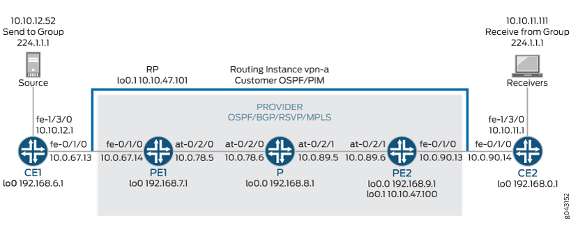
그림 4에 표시된 네트워크에 대해 MBGP 멀티캐스트 VPN을 구성하려면 다음 단계를 수행합니다.
인터페이스 구성
단계별 절차
다음 예제에서는 구성 계층의 다양한 수준을 탐색해야 합니다. CLI 탐색에 대한 정보는 CLI 사용자 가이드의 구성 모드에서 CLI 편집기 사용을 참조하십시오.
각 라우터에서 루프백 논리적 인터페이스 0(
lo0.0)에 IP 주소를 구성합니다.[edit interfaces] user@CE1# set lo0 unit 0 family inet address 192.168.6.1/32 primary user@PE1# set lo0 unit 0 family inet address 192.168.7.1/32 primary user@P# set lo0 unit 0 family inet address 192.168.8.1/32 primary user@PE2# set lo0 unit 0 family inet address 192.168.9.1/32 primary user@CE2# set lo0 unit 0 family inet address 192.168.0.1/32 primary
show interfaces terse명령을 사용하여 루프백 논리적 인터페이스에서 IP 주소가 정확한지 확인합니다.PE 및 CE 라우터의 고속 이더넷 인터페이스에서 IP 주소 및 프로토콜 제품군을 구성합니다.
inet프로토콜 제품군 유형을 지정합니다.[edit interfaces] user@CE1# set fe-1/3/0 unit 0 family inet address 10.10.12.1/24 user@CE1# set fe-0/1/0 unit 0 family inet address 10.0.67.13/30 [edit interfaces] user@PE1# set fe-0/1/0 unit 0 family inet address 10.0.67.14/30 [edit interfaces] user@PE2# set fe-0/1/0 unit 0 family inet address 10.0.90.13/30 [edit interfaces] user@CE2# set fe-0/1/0 unit 0 family inet address 10.0.90.14/30 user@CE2# set fe-1/3/0 unit 0 family inet address 10.10.11.1/24
show interfaces terse명령을 사용하여 고속 이더넷 인터페이스에서 IP 주소가 올바른지 확인합니다.PE 및 P 라우터에서 ATM 인터페이스의 VPI 및 최대 가상 회로를 구성합니다. 직접 연결된 ATM 인터페이스에서 기본 PIC 유형이 다른 경우 PIC 유형을 동일하게 구성합니다. 논리적 인터페이스 VCI, 프로토콜 제품군, 로컬 IP 주소 및 대상 IP 주소를 구성합니다.
[edit interfaces]
user@PE1# set at-0/2/0 atm-options pic-type atm1
user@PE1# set at-0/2/0 atm-options vpi 0 maximum-vcs 256
user@PE1# set at-0/2/0 unit 0 vci 0.128
user@PE1# set at-0/2/0 unit 0 family inet address 10.0.78.5/32 destination 10.0.78.6

[edit interfaces]
user@P# set at-0/2/0 atm-options pic-type atm1
user@P# set at-0/2/0 atm-options vpi 0 maximum-vcs 256
user@P# set at-0/2/0 unit 0 vci 0.128
user@P# set at-0/2/0 unit 0 family inet address 10.0.78.6/32 destination 10.0.78.5
user@P# set at-0/2/1 atm-options pic-type atm1
user@P# set at-0/2/1 atm-options vpi 0 maximum-vcs 256
user@P# set at-0/2/1 unit 0 vci 0.128
user@P# set at-0/2/1 unit 0 family inet address 10.0.89.5/32 destination 10.0.89.6

[edit interfaces]
user@PE2# set at-0/2/1 atm-options pic-type atm1
user@PE2# set at-0/2/1 atm-options vpi 0 maximum-vcs 256
user@PE2# set at-0/2/1 unit 0 vci 0.128
user@PE2# set at-0/2/1 unit 0 family inet address 10.0.89.6/32 destination 10.0.89.5
show configuration interfaces명령을 사용하여 ATM 인터페이스의 VPI 및 최대 VC가 올바른지, 논리적 인터페이스 VCI, 프로토콜 제품군, 로컬 IP 주소 및 대상 IP 주소가 올바른지 확인합니다.
OSPF 구성
단계별 절차
P 및 PE 라우터에서 OSPF의 공급자 인스턴스를 구성합니다.
lo0.0및 ATM 코어 대면 논리적 인터페이스를 지정합니다. PE 라우터에 있는 OSPF의 공급자 인스턴스는 다른 PE 라우터 및 라우터 P에 있는 OSPF neighbor와 인접성을 형성합니다.user@PE1# set protocols ospf area 0.0.0.0 interface at-0/2/0.0 user@PE1# set protocols ospf area 0.0.0.0 interface lo0.0 user@P# set protocols ospf area 0.0.0.0 interface lo0.0 user@P# set protocols ospf area 0.0.0.0 interface all user@P# set protocols ospf area 0.0.0.0 interface fxp0 disable user@PE2# set protocols ospf area 0.0.0.0 interface lo0.0 user@PE2# set protocols ospf area 0.0.0.0 interface at-0/2/1.0
show ospf interfaces명령을 사용하여 및 ATM 코어 대면 논리적 인터페이스가 OSPF에 대해 구성되었는지lo0.0확인합니다.CE 라우터에서 OSPF의 고객 인스턴스를 구성합니다. 루프백 및 고속 이더넷 논리적 인터페이스를 지정합니다. CE 라우터에서 OSPF의 고객 인스턴스는 PE 라우터에서 OSPF의 VPN 라우팅 인스턴스 내의 인접 항목과 인접성을 형성합니다.
user@CE1# set protocols ospf area 0.0.0.0 interface fe-0/1/0.0
user@CE1# set protocols ospf area 0.0.0.0 interface fe-1/3/0.0
user@CE1# set protocols ospf area 0.0.0.0 interface lo0.0

user@CE2# set protocols ospf area 0.0.0.0 interface fe-0/1/0.0
user@CE2# set protocols ospf area 0.0.0.0 interface fe-1/3/0.0
user@CE2# set protocols ospf area 0.0.0.0 interface lo0.0
show ospf interfaces명령을 사용하여 올바른 루프백 및 고속 이더넷 논리적 인터페이스가 OSPF 프로토콜에 추가되었는지 확인합니다.P 및 PE 라우터에서 OSPF의 프로바이더 인스턴스에 대한 OSPF 트래픽 엔지니어링 지원을 구성합니다.
명령문은
shortcutsOSPF의 마스터 인스턴스가 레이블 전환 경로를 다음 홉으로 사용할 수 있도록 합니다.user@PE1# set protocols ospf traffic-engineering shortcuts user@P# set protocols ospf traffic-engineering shortcuts user@PE2# set protocols ospf traffic-engineering shortcuts
또는
show configuration protocols ospf명령을show ospf overview사용하여 트래픽 엔지니어링 지원이 활성화되었는지 확인합니다.
BGP 구성
단계별 절차
라우터 P에서 VPN에 대한 BGP를 구성합니다. 로컬 주소는 로컬
lo0.0주소입니다. 이웃 주소는 PE 라우터lo0.0의 주소입니다.명령문은 라우터가
unicastBGP를 사용하여 NLRI(Network Layer Reachability Information)를 보급할 수 있도록 합니다. 명령문은 라우터가signalingBGP를 VPN의 신호 프로토콜로 사용할 수 있도록 합니다.user@P# set protocols bgp group group-mvpn type internal user@P# set protocols bgp group group-mvpn local-address 192.168.8.1 user@P# set protocols bgp group group-mvpn family inet unicast user@P# set protocols bgp group group-mvpn family inet-mvpn signaling user@P# set protocols bgp group group-mvpn neighbor 192.168.9.1 user@P# set protocols bgp group group-mvpn neighbor 192.168.7.1
show configuration protocols bgp명령을 사용하여 라우터가 BGP를 사용하여 NLRI를 보급하도록 구성되었는지 확인합니다.PE 및 P 라우터에서 BGP 로컬 AS(Autonomous System) 번호를 구성합니다.
user@PE1# set routing-options autonomous-system 0.65010

user@P# set routing-options autonomous-system 0.65010

user@PE2# set routing-options autonomous-system 0.65010
show configuration routing-options명령을 사용하여 BGP 로컬 자동 시스템 번호가 올바른지 확인합니다.PE 라우터에서 VPN용 BGP를 구성합니다. 로컬 주소를 로컬
lo0.0주소로 구성합니다. 이웃 주소는 라우터 P와 다른 PE 라우터인 PE2의 주소입니다lo0.0.user@PE1# set protocols bgp group group-mvpn type internal user@PE1# set protocols bgp group group-mvpn local-address 192.168.7.1 user@PE1# set protocols bgp group group-mvpn family inet-vpn unicast user@PE1# set protocols bgp group group-mvpn family inet-mvpn signaling user@PE1# set protocols bgp group group-mvpn neighbor 192.168.9.1 user@PE1# set protocols bgp group group-mvpn neighbor 192.168.8.1 user@PE2# set protocols bgp group group-mvpn type internal user@PE2# set protocols bgp group group-mvpn local-address 192.168.9.1 user@PE2# set protocols bgp group group-mvpn family inet-vpn unicast user@PE2# set protocols bgp group group-mvpn family inet-mvpn signaling user@PE2# set protocols bgp group group-mvpn neighbor 192.168.7.1 user@PE2# set protocols bgp group group-mvpn neighbor 192.168.8.1
show bgp group명령을 사용하여 BGP 구성이 올바른지 확인합니다.PE 라우터에서 BGP 경로를 OSPF로 내보내는 정책을 구성합니다.
user@PE1# set policy-options policy-statement bgp-to-ospf from protocol bgp
user@PE1# set policy-options policy-statement bgp-to-ospf then accept

user@PE2# set policy-options policy-statement bgp-to-ospf from protocol bgp
user@PE2# set policy-options policy-statement bgp-to-ospf then accept
show policy bgp-to-ospf명령을 사용하여 정책이 올바른지 확인합니다.
RSVP 구성
단계별 절차
PE 라우터에서 LSP에 참여하는 인터페이스에서 RSVP를 활성화합니다. 고속 이더넷 및 ATM 논리적 인터페이스를 구성합니다.
user@PE1# set protocols rsvp interface fe-0/1/0.0
user@PE1# set protocols rsvp interface at-0/2/0.0

user@PE2# set protocols rsvp interface fe-0/1/0.0
user@PE2# set protocols rsvp interface at-0/2/1.0
라우터 P에서 LSP에 참여하는 인터페이스에 RSVP를 활성화합니다. ATM 논리적 인터페이스를 구성합니다.
user@P# set protocols rsvp interface at-0/2/0.0
user@P# set protocols rsvp interface at-0/2/1.0
show configuration protocols rsvp명령을 사용하여 RSVP 구성이 올바른지 확인합니다.
MPLS 구성
단계별 절차
PE 라우터에서 LSP 송신 지점인 PE 라우터에 MPLS LSP를 구성합니다. LSP의
lo0.0다른 쪽 끝에 있는 라우터에 있는 인터페이스의 IP 주소를 지정합니다. ATM, 고속 이더넷 및lo0.0인터페이스에서 MPLS를 구성합니다.문제 해결 시 각 LSP를 식별하려면 각 PE 라우터에서 다른 LSP 이름을 구성합니다. 이 예에서는 PE1에 구성된 LSP의 이름으로 이름을
to-pe2사용하고to-pe1PE2에 구성된 LSP의 이름으로 사용합니다.user@PE1# set protocols mpls label-switched-path to-pe2 to 192.168.9.1 user@PE1# set protocols mpls interface fe-0/1/0.0 user@PE1# set protocols mpls interface at-0/2/0.0 user@PE1# set protocols mpls interface lo0.0 user@PE2# set protocols mpls label-switched-path to-pe1 to 192.168.7.1 user@PE2# set protocols mpls interface fe-0/1/0.0 user@PE2# set protocols mpls interface at-0/2/1.0 user@PE2# set protocols mpls interface lo0.0
및
show route label-switched-path to-pe1명령을show configuration protocols mpls사용하여 MPLS 및 LSP 구성이 올바른지 확인합니다.구성이 커밋된 후 및
show mpls lsp name to-pe2명령을 사용하여show mpls lsp name to-pe1LSP가 작동하는지 확인합니다.라우터 P에서 MPLS를 활성화합니다. PE 라우터에 연결된 ATM 인터페이스를 지정합니다.
user@P# set protocols mpls interface at-0/2/0.0
user@P# set protocols mpls interface at-0/2/1.0
show mpls interface명령을 사용하여 ATM 인터페이스에서 MPLS가 사용하도록 설정되었는지 확인합니다.PE 및 P 라우터에서 LSP와 연결된 ATM 인터페이스에 프로토콜 패밀리를 구성합니다.
mpls프로토콜 제품군 유형을 지정합니다.user@PE1# set interfaces at-0/2/0 unit 0 family mpls user@P# set interfaces at-0/2/0 unit 0 family mpls user@P# set interfaces at-0/2/1 unit 0 family mpls user@PE2# set interfaces at-0/2/1 unit 0 family mpls
show mpls interface명령을 사용하여 LSP와 연결된 ATM 인터페이스에서 MPLS 프로토콜 패밀리가 활성화되었는지 확인합니다.
VRF 라우팅 인스턴스 구성
단계별 절차
PE 라우터에서 VPN에 대한 라우팅 인스턴스를 구성하고 인스턴스 유형을 지정합니다
vrf. 고속 이더넷 및lo0.1고객 대면 인터페이스를 추가합니다. OSPF의 VPN 인스턴스를 구성하고 BGP-OSPF 내보내기 정책을 포함합니다.user@PE1# set routing-instances vpn-a instance-type vrf user@PE1# set routing-instances vpn-a interface lo0.1 user@PE1# set routing-instances vpn-a interface fe-0/1/0.0 user@PE1# set routing-instances vpn-a protocols ospf export bgp-to-ospf user@PE1# set routing-instances vpn-a protocols ospf area 0.0.0.0 interface all user@PE2# set routing-instances vpn-a instance-type vrf user@PE2# set routing-instances vpn-a interface lo0.1 user@PE2# set routing-instances vpn-a interface fe-0/1/0.0 user@PE2# set routing-instances vpn-a protocols ospf export bgp-to-ospf user@PE2# set routing-instances vpn-a protocols ospf area 0.0.0.0 interface all
show configuration routing-instances vpn-a명령을 사용하여 라우팅 인스턴스 구성이 올바른지 확인합니다.PE 라우터에서 라우팅 인스턴스에 대한 경로 식별자를 구성합니다. 경로 구분자를 사용하면 라우터가 VPN 경로로 사용되는 두 개의 동일한 IP 접두사를 구별할 수 있습니다. 각 PE 라우터에서 다른 경로 식별자를 구성합니다. 이 예에서는 PE1에서 65010:1, PE2에서 65010:2를 사용합니다.
user@PE1# set routing-instances vpn-a route-distinguisher 65010:1

user@PE2# set routing-instances vpn-a route-distinguisher 65010:2
show configuration routing-instances vpn-a명령을 사용하여 경로 구분자가 올바른지 확인합니다.PE 라우터에서 기본 VRF 가져오기 및 내보내기 정책을 구성합니다. 이 구성을 기반으로 BGP는 VRF 가져오기 정책에서 참조되는 경로 대상에 해당하는 로컬 경로를 자동으로 생성합니다. 이 예에서는 2:1을 경로 대상으로 사용합니다.
메모:지정된 VPN 라우팅 인스턴스에 대해 각 PE 라우터에서 동일한 경로 대상을 구성해야 합니다.
user@PE1# set routing-instances vpn-a vrf-target target:2:1

user@PE2# set routing-instances vpn-a vrf-target target:2:1
show configuration routing-instances vpn-a명령을 사용하여 경로 대상이 올바른지 확인합니다.PE 라우터에서 멀티캐스트 지원을 위한 VPN 라우팅 인스턴스를 구성합니다.
user@PE1# set routing-instances vpn-a protocols mvpn

user@PE2# set routing-instances vpn-a protocols mvpn
show configuration routing-instance vpn-a명령을 사용하여 VPN 라우팅 인스턴스가 멀티캐스트 지원을 위해 구성되었는지 확인합니다.PE 라우터에서 고객 라우팅 인스턴스 VPN에 사용되는 루프백 논리적 인터페이스 1(
lo0.1)의 IP 주소를 구성합니다.user@PE1# set interfaces lo0 unit 1 family inet address 10.10.47.101/32 user@PE2# set interfaces lo0 unit 1 family inet address 10.10.47.100/32
show interfaces terse명령을 사용하여 루프백 인터페이스의 IP 주소가 올바른지 확인합니다.
PIM 구성
단계별 절차
PE 라우터에서 PIM을 활성화합니다.
lo0.1고객 대면 고속 이더넷 인터페이스를 구성합니다. 모드를 로sparse지정하고 버전을 로2지정합니다.user@PE1# set routing-instances vpn-a protocols pim interface lo0.1 mode sparse user@PE1# set routing-instances vpn-a protocols pim interface lo0.1 version 2 user@PE1# set routing-instances vpn-a protocols pim interface fe-0/1/0.0 mode sparse user@PE1# set routing-instances vpn-a protocols pim interface fe-0/1/0.0 version 2 user@PE2# set routing-instances vpn-a protocols pim interface lo0.1 mode sparse user@PE2# set routing-instances vpn-a protocols pim interface lo0.1 version 2 user@PE2# set routing-instances vpn-a protocols pim interface fe-0/1/0.0 mode sparse user@PE2# set routing-instances vpn-a protocols pim interface fe-0/1/0.0 version 2
show pim interfaces instance vpn-a명령을 사용하여 인터페이스 및 고객 대면 고속 이더넷 인터페이스에서 PIM 스파스 모드가 활성화lo0.1되었는지 확인합니다.CE 라우터에서 PIM을 활성화합니다. 이 예에서는 모든 인터페이스를 구성합니다. 모드를 로
sparse지정하고 버전을 로2지정합니다.user@CE1# set protocols pim interface all user@CE2# set protocols pim interface all mode sparse user@CE2# set protocols pim interface all version 2
show pim interfaces명령을 사용하여 모든 인터페이스에서 PIM 스파스 모드가 사용하도록 설정되었는지 확인합니다.
프로바이더 터널 구성
단계별 절차
라우터 PE1에서 프로바이더 터널을 구성합니다. 사용할 멀티캐스트 주소를 지정합니다.
명령문은 라우터에
provider-tunnel터널을 통해 멀티캐스트 트래픽을 전송하도록 지시합니다.user@PE1# set routing-instances vpn-a provider-tunnel rsvp-te label-switched-path-template default-template
show configuration routing-instance vpn-a명령을 사용하여 공급자 터널이 기본 LSP 템플릿을 사용하도록 구성되었는지 확인합니다.라우터 PE2에서 프로바이더 터널을 구성합니다. 사용할 멀티캐스트 주소를 지정합니다.
user@PE2# set routing-instances vpn-a provider-tunnel rsvp-te label-switched-path-template default-template
show configuration routing-instance vpn-a명령을 사용하여 공급자 터널이 기본 LSP 템플릿을 사용하도록 구성되었는지 확인합니다.
랑데부 지점 구성
단계별 절차
라우터 PE1을 랑데부 지점으로 구성합니다. 라우터 PE1의
lo0.1주소를 지정합니다. 사용할 멀티캐스트 주소를 지정합니다.user@PE1# set routing-instances vpn-a protocols pim rp local address 10.10.47.101 user@PE1# set routing-instances vpn-a protocols pim rp local group-ranges 224.1.1.1/32
show pim rps instance vpn-a명령을 사용하여 RP에 대해 올바른 로컬 IP 주소가 구성되었는지 확인합니다.라우터 PE2에서 정적 랑데부 지점을 구성합니다. 라우터 PE1의
lo0.1주소를 지정합니다.user@PE2# set routing-instances vpn-a protocols pim rp static address 10.10.47.101
show pim rps instance vpn-a명령을 사용하여 RP에 대해 올바른 정적 IP 주소가 구성되었는지 확인합니다.CE 라우터에서 정적 랑데부 지점을 구성합니다. 라우터 PE1의
lo0.1주소를 지정합니다.user@CE1# set protocols pim rp static address 10.10.47.101 version 2 user@CE2# set protocols pim rp static address 10.10.47.101 version 2
show pim rps명령을 사용하여 RP에 대해 올바른 정적 IP 주소가 구성되었는지 확인합니다.commit check명령을 사용하여 구성이 성공적으로 커밋될 수 있는지 확인합니다. 구성이 검사를 통과하면 구성을 커밋합니다.CE1에 연결된 멀티캐스트 발신자 디바이스를 시작합니다.
CE2에 연결된 멀티캐스트 수신기 디바이스를 시작합니다.
수신기가 멀티캐스트 스트림을 수신하고 있는지 확인합니다.
명령을 사용하여
show라우팅, VPN 및 멀티캐스트 작업을 확인합니다.
결과
이 예의 구성 및 확인 부분이 완료되었습니다. 다음 섹션은 참조용입니다.
라우터 CE1에 대한 관련 샘플 구성은 다음과 같습니다.
라우터 CE1
interfaces {
    lo0 {
        unit 0 {
            family inet {
                address 192.168.6.1/32 {
                    primary;
                }
            }
        }
    }
    fe-0/1/0 {
        unit 0 {
            family inet {
                address 10.0.67.13/30;
            }
        }
    }
    fe-1/3/0 {
        unit 0 {
            family inet {
                address 10.10.12.1/24;
            }
        }
    }
}
protocols {
    ospf {
        area 0.0.0.0 {
            interface fe-0/1/0.0;
            interface lo0.0;
            interface fe-1/3/0.0;
        }
    }
    pim {
        rp {
            static {
                address 10.10.47.101 {
                    version 2;
                }
            }
        }
        interface all;
    }
}
라우터 PE1에 대한 관련 샘플 구성은 다음과 같습니다.
라우터 PE1
interfaces {
    lo0 {
        unit 0 {
            family inet {
                address 192.168.7.1/32 {
                    primary;
                }
            }
        }
    }
    fe-0/1/0 {
        unit 0 {
            family inet {
                address 10.0.67.14/30;
            }
        }
    }
    at-0/2/0 {
        atm-options {
            pic-type atm1;
            vpi 0 {
                maximum-vcs 256;
            }
        }
        unit 0 {
            vci 0.128;
            family inet {
                address 10.0.78.5/32 {
                    destination 10.0.78.6;
                }
            }
            family mpls;
        }
    }
    lo0 {
        unit 1 {
            family inet {
                address 10.10.47.101/32;
            }
        }
    }
}
routing-options {
    autonomous-system 0.65010;
}
protocols {
    rsvp {
        interface fe-0/1/0.0;
        interface at-0/2/0.0;
    }
    mpls {
        label-switched-path to-pe2 {
            to 192.168.9.1;
        }
        interface fe-0/1/0.0;
        interface at-0/2/0.0;
        interface lo0.0;
    }
    bgp {
        group group-mvpn {
            type internal;
            local-address 192.168.7.1;
            family inet-vpn {
                unicast;
            }
            family inet-mvpn {
                signaling;
            }
            neighbor 192.168.9.1;
            neighbor 192.168.8.1;
        }
    }
    ospf {
        traffic-engineering {
            shortcuts;
        }
        area 0.0.0.0 {
            interface at-0/2/0.0;
            interface lo0.0;
        }
    }
}
policy-options {
    policy-statement bgp-to-ospf {
        from protocol bgp;
        then accept;
    }
}
routing-instances {
    vpn-a {
        instance-type vrf;
        interface lo0.1;
        interface fe-0/1/0.0;
        route-distinguisher 65010:1;
        provider-tunnel {
            rsvp-te {
                label-switched-path-template {
                    default-template;
                }
            }
        }
        vrf-target target:2:1;
        protocols {
            ospf {
                export bgp-to-ospf;
                area 0.0.0.0 {
                    interface all;
                }
            }
            pim {
                rp {
                    local {
                        address 10.10.47.101;
                        group-ranges {
                            224.1.1.1/32;
                        }
                    }
                }
                interface lo0.1 {
                    mode sparse;
                    version 2;
                }
                interface fe-0/1/0.0 {
                    mode sparse;
                    version 2;
                }
            }
            mvpn;
        }
    }
}
라우터 P에 대한 관련 샘플 구성은 다음과 같습니다.
라우터 P
interfaces {
    lo0 {
        unit 0 {
            family inet {
                address 192.168.8.1/32 {
                    primary;
                }
            }
        }
    }
    at-0/2/0 {
        atm-options {
            pic-type atm1;
            vpi 0 {
                maximum-vcs 256;
            }
        }
        unit 0 {
            vci 0.128;
            family inet {
                address 10.0.78.6/32 {
                    destination 10.0.78.5;
                }
            }
            family mpls;
        }
    }
    at-0/2/1 {
        atm-options {
            pic-type atm1;
            vpi 0 {
                maximum-vcs 256;
            }
        }
        unit 0 {
            vci 0.128;
            family inet {
                address 10.0.89.5/32 {
                    destination 10.0.89.6;
                }
            }
            family mpls;
        }
    }
}
routing-options {
    autonomous-system 0.65010;
}
protocols {
    rsvp {
        interface at-0/2/0.0;
        interface at-0/2/1.0;
    }
    mpls {
        interface at-0/2/0.0;
        interface at-0/2/1.0;
    }
    bgp {
        group group-mvpn {
            type internal;
            local-address 192.168.8.1;
            family inet {
                unicast;
            }
            family inet-mvpn {
                signaling;
            }
            neighbor 192.168.9.1;
            neighbor 192.168.7.1;
        }
    }
    ospf {
        traffic-engineering {
            shortcuts;
        }
        area 0.0.0.0 {
            interface lo0.0;
            interface all;
            interface fxp0.0 {
                disable;
            }
        }
    }
}
라우터 PE2에 대한 관련 샘플 구성은 다음과 같습니다.
라우터 PE2
interfaces {
    lo0 {
        unit 0 {
            family inet {
                address 192.168.9.1/32 {
                    primary;
                }
            }
        }
    }
    fe-0/1/0 {
        unit 0 {
            family inet {
                address 10.0.90.13/30;
            }
        }
    }
    at-0/2/1 {
        atm-options {
            pic-type atm1;
            vpi 0 {
                maximum-vcs 256;
            }
        }
        unit 0 {
            vci 0.128;
            family inet {
                address 10.0.89.6/32 {
                    destination 10.0.89.5;
                }
            }
            family mpls;
        }
    }
    lo0 {
        unit 1 {
            family inet {
                address 10.10.47.100/32;
            }
        }
    }
}
routing-options {
    autonomous-system 0.65010;
}
protocols {
    rsvp {
        interface fe-0/1/0.0;
        interface at-0/2/1.0;
    }
    mpls {
        label-switched-path to-pe1 {
            to 192.168.7.1;
        }
        interface lo0.0;
        interface fe-0/1/0.0;
        interface at-0/2/1.0;
    }
    bgp {
        group group-mvpn {
            type internal;
            local-address 192.168.9.1;
            family inet-vpn {
                unicast;
            }
            family inet-mvpn {
                signaling;
            }
            neighbor 192.168.7.1;
            neighbor 192.168.8.1;
        }
    }
    ospf {
        traffic-engineering {
            shortcuts;
        }
        area 0.0.0.0 {
            interface lo0.0;
            interface at-0/2/1.0;
        }
    }
}
policy-options {
    policy-statement bgp-to-ospf {
        from protocol bgp;
        then accept;
    }
}
routing-instances {
    vpn-a {
        instance-type vrf;
        interface fe-0/1/0.0;
        interface lo0.1;
        route-distinguisher 65010:2;
        provider-tunnel {
            rsvp-te {
                label-switched-path-template {
                    default-template;
                }
            }
        }
        vrf-target target:2:1;
        protocols {
            ospf {
                export bgp-to-ospf;
                area 0.0.0.0 {
                    interface all;
                }
            }
            pim {
                rp {
                    static {
                        address 10.10.47.101;
                    }
                }
                interface fe-0/1/0.0 {
                    mode sparse;
                    version 2;
                }
                interface lo0.1 {
                    mode sparse;
                    version 2;
                }
            }
            mvpn;
        }
    }
}
라우터 CE2에 대한 관련 샘플 구성은 다음과 같습니다.
라우터 CE2
interfaces {
    lo0 {
        unit 0 {
            family inet {
                address 192.168.0.1/32 {
                    primary;
                }
            }
        }
    }
    fe-0/1/0 {
        unit 0 {
            family inet {
                address 10.0.90.14/30;
            }
        }
    }
    fe-1/3/0 {
        unit 0 {
            family inet {
                address 10.10.11.1/24;
            }
            family inet6 {
                address fe80::205:85ff:fe88:ccdb/64;
            }
        }
    }
}
protocols {
    ospf {
        area 0.0.0.0 {
            interface fe-0/1/0.0;
            interface lo0.0;
            interface fe-1/3/0.0;
        }
    }
    pim {
        rp {
            static {
                address 10.10.47.101 {
                    version 2;
                }
            }
        }
        interface all {
            mode sparse;
            version 2;
        }
    }
}
예: MBGP MVPN을 위한 PIM-SSM 프로바이더 터널 구성
이 예는 MBGP MVPN에 대한 PIM-SSM 공급자 터널을 구성하는 방법을 보여줍니다. 이 구성을 통해 서비스 프로바이더는 고객 데이터를 코어에 전달할 수 있습니다. 이 예에서는 PIM-SSM 터널을 포괄적인 PMSI로 구성하는 방법을 보여주며, 단일 포워더를 결정하기 위한 메트릭으로 유니캐스트 라우팅 기본 설정을 사용합니다(기본 메트릭인 route-import 커뮤니티의 전역 관리자 필드의 IP 주소 대신).
요구 사항
시작하기 전에:
-
라우터 인터페이스를 구성합니다. 라우팅 디바이스용 Junos OS 네트워크 인터페이스 라이브러리를 참조하십시오.
-
BGP-OSPF 라우팅 정책을 구성합니다. 라우팅 정책, 방화벽 필터 및 트래픽 폴리서 사용자 가이드를 참조하십시오.
개요
PE가 CE로부터 고객 참가 또는 정리 메시지를 수신하면 메시지는 특정 멀티캐스트 플로우가 소스별 트리(S,G) 또는 공유 트리(*,G)에 속하는 것으로 식별합니다. 멀티캐스트 소스 또는 RP에 대한 경로가 VPN 백본을 통과하는 경우 PE는 (S,G) 또는 (*,G) 흐름에 대한 업스트림 멀티캐스트 홉(UMH)을 식별해야 합니다. 일반적으로 UMH는 멀티캐스트 소스 또는 RP에 대한 유니캐스트 경로에 의해 결정됩니다.
그러나 경우에 따라 CE는 경로 가져오기 커뮤니티를 사용하여 업스트림 멀티캐스트 홉 선택 목적으로만 사용되는 특별한 경로 집합을 PE에 배포할 수 있습니다. 둘 이상의 경로가 적격할 수 있으며 PE는 적격 UMH에서 단일 포워더를 선택해야 합니다.
단일 전달자 선택에 대한 기본 메트릭은 route-import 커뮤니티의 전역 관리자 필드에 있는 IP 주소입니다. 유니캐스트 경로 기본 설정을 사용하도록 라우터를 구성하여 단일 포워더 선택을 결정할 수 있습니다.
이 예제에는 다음 설정이 포함되어 있습니다.
-
provider-tunnel family inet pim-ssm group-address - 유효한 SSM VPN 그룹 주소를 지정합니다. SSM VPN 그룹 주소 및 소스 주소는 type-1 자동 검색 라우팅에 의해 보급됩니다. SSM VPN 그룹 주소와 소스 주소가 포함된 자동 검색 경로를 수신하면 PE 라우터는 자동 검색 경로를 광고하는 PE에 공급자 공간의 (S,G) 조인을 보냅니다. 모든 PE 라우터는 PIM-SSM VPN 그룹 주소를 교환하여 I-PMSI(Inclusive Provider Multicast Service Interface)를 완료합니다. PIM-ASM 공급자 터널과 달리 PE 라우터는 (S, G) 조인이 소스 PE로 직접 전송되기 때문에 다른 VPN 그룹 주소를 선택할 수 있습니다.
메모:PIM-ASM 제공자 터널과 마찬가지로 PIM은 기본 마스터 인스턴스에서 구성해야 합니다.
-
unicast-umh-election - PE 라우터가 유니캐스트 경로 기본 설정을 사용하여 단일 포워더 선택을 결정하도록 지정합니다.
구성
절차
CLI 빠른 구성
이 예를 빠르게 구성하려면, 아래 명령을 복사하여 텍스트 파일로 붙여 넣은 다음 모든 라인브레이크를 제거하고, 네트워크 구성을 일치하는 데 필요한 세부 사항을 변경한 다음, 계층 수준에서 명령을 CLI로 [edit] 복사해 붙여 넣습니다.
set interfaces fe-0/2/0 unit 0 family inet address 192.168.195.109/30
set interfaces fe-0/2/1 unit 0 family inet address 192.168.195.5/27
set interfaces fe-0/2/2 unit 0 family inet address 10.20.1.1/30
set interfaces fe-0/2/2 unit 0 family iso
set interfaces fe-0/2/2 unit 0 family mpls
set interfaces lo0 unit 1 family inet address 10.10.47.100/32
set interfaces lo0 unit 1 family inet address 192.168.195.1/32 primary
set interfaces lo0 unit 2 family inet address 10.10.48.100/32
set protocols mpls interface all set protocols bgp group ibgp type internal
set protocols bgp group ibgp local-preference 120
set protocols bgp group ibgp family inet-vpn any
set protocols bgp group ibgp family inet-mvpn signaling
set protocols bgp group ibgp neighbor 10.255.112.155
set protocols isis level 1 disable set protocols isis interface all
set protocols isis interface fxp0.0 disable
set protocols ospf traffic-engineering
set protocols ospf area 0.0.0.0 interface all
set protocols ospf area 0.0.0.0 interface fxp0.0 disable
set protocols ldp interface all
set protocols pim rp static address 10.255.112.155
set protocols pim interface all mode sparse-dense
set protocols pim interface all version 2
set protocols pim interface fxp0.0 disable
set routing-instances VPN-A instance-type vrf
set routing-instances VPN-A interface fe-0/2/1.0
set routing-instances VPN-A interface lo0.1
set routing-instances VPN-A route-distinguisher 10.255.112.199:100
set routing-instances VPN-A provider-tunnel family inet pim-ssm group-address 233.252.0.1
set routing-instances VPN-A vrf-target target:10:100
set routing-instances VPN-A vrf-table-label
set routing-instances VPN-A routing-options auto-export
set routing-instances VPN-A protocols ospf export bgp-to-ospf
set routing-instances VPN-A protocols ospf area 0.0.0.0 interface lo0.1
set routing-instances VPN-A protocols ospf area 0.0.0.0 interface fe-0/2/1.0
set routing-instances VPN-A protocols pim rp static address 10.10.47.101
set routing-instances VPN-A protocols pim interface lo0.1 mode sparse-dense
set routing-instances VPN-A protocols pim interface lo0.1 version 2
set routing-instances VPN-A protocols pim interface fe-0/2/1.0 mode sparse-dense
set routing-instances VPN-A protocols pim interface fe-0/2/1.0 version 2
set routing-instances VPN-A protocols mvpn unicast-umh-election
set routing-instances VPN-B instance-type vrf
set routing-instances VPN-B interface fe-0/2/0.0
set routing-instances VPN-B interface lo0.2
set routing-instances VPN-B route-distinguisher 10.255.112.199:200
set routing-instances VPN-B provider-tunnel family inet pim-ssm group-address 233.252.0.2
set routing-instances VPN-B vrf-target target:10:200
set routing-instances VPN-B vrf-table-label
set routing-instances VPN-B routing-options auto-export
set routing-instances VPN-B protocols ospf export bgp-to-ospf
set routing-instances VPN-B protocols ospf area 0.0.0.0 interface lo0.2
set routing-instances VPN-B protocols ospf area 0.0.0.0 interface fe-0/2/0.0
set routing-instances VPN-B protocols pim rp static address 10.10.48.101
set routing-instances VPN-B protocols pim interface lo0.2 mode sparse-dense
set routing-instances VPN-B protocols pim interface lo0.2 version 2
set routing-instances VPN-B protocols pim interface fe-0/2/0.0 mode sparse-dense
set routing-instances VPN-B protocols pim interface fe-0/2/0.0 version 2
set routing-instances VPN-B protocols mvpn unicast-umh-election
set routing-options autonomous-system 65100
단계별 절차
다음 예제에서는 구성 계층의 다양한 수준을 탐색해야 합니다. CLI 탐색에 대한 자세한 내용은 Junos OS CLI 사용자 가이드의 구성 모드에서 CLI 편집기 사용을 참조하십시오.
MBGP MVPN에 대한 PIM-SSM 공급자 터널을 구성하려면 다음을 수행합니다.
-
PE 라우터의 마스터 라우팅 인스턴스에서 인터페이스를 구성합니다. 이 예에서는 하나의 PE 라우터에 대한 인터페이스를 보여줍니다.
[edit interfaces]
user@host# set fe-0/2/0 unit 0 family inet address 192.168.195.109/30
user@host# set fe-0/2/1 unit 0 family inet address 192.168.195.5/27
user@host# set fe-0/2/2 unit 0 family inet address 10.20.1.1/30
user@host# set fe-0/2/2 unit 0 family iso
user@host# set fe-0/2/2 unit 0  family mpls
user@host# set lo0 unit 1 family inet address 10.10.47.100/32
user@host# set lo0 unit 2 family inet address 10.10.48.100/32
-
글로벌 라우팅 옵션에서 AS(Autonomous System) 번호를 구성합니다. 이는 MBGP MVPN에서 필요합니다.
[edit routing-options]
user@host# set autonomous-system 65100
-
PE 라우터의 마스터 라우팅 인스턴스에서 라우팅 프로토콜을 구성합니다.
[edit protocols bgp group ibgp]
user@host# set type internal
user@host# set family inet-vpn any
user@host# set family inet-mvpn signaling
user@host# set neighbor 10.255.112.155
[edit protocols isis]
user@host# set level 1 disable
user@host# set interface all
user@host# set interface fxp0.0 disable
[edit protocols ospf]
user@host# set traffic-engineering
user@host# set area 0.0.0.0 interface all
user@host# set area 0.0.0.0 interface fxp0.0 disable
user@host# set protocols ldp interface all
[edit protocols pim]
user@host# set rp static address 10.255.112.155
user@host# set interface all mode sparse-dense
user@host# set interface all version 2
user@host# set interface fxp0.0 disable
-
라우팅 인스턴스 VPN-A를 구성합니다.
[edit routing-instances VPN-A]
user@host# set instance-type vrf
user@host# set interface fe-0/2/1.0
user@host# set interface lo0.1
user@host# set route-distinguisher 10.255.112.199:100
user@host# set provider-tunnel family inet pim-ssm group-address 232.252.0.1
user@host# set vrf-target target:10:100
user@host# set vrf-table-label
user@host# set routing-options auto-export
user@host# set protocols ospf export bgp-to-ospf
user@host# set protocols ospf area 0.0.0.0 interface lo0.1
user@host# set protocols ospf area 0.0.0.0 interface fe-0/2/1.0
user@host# set protocols pim rp static address 10.10.47.101
user@host# set protocols pim interface lo0.1 mode sparse-dense
user@host# set protocols pim interface lo0.1 version 2
user@host# set protocols pim interface fe-0/2/1.0 mode sparse-dense
user@host# set protocols pim interface fe-0/2/1.0  version 2
user@host# set protocols mvpn unicast-umh-election
-
라우팅 인스턴스 VPN-B를 구성합니다.
[edit routing-instances VPN-B]
user@host# set instance-type vrf
user@host# set interface fe-0/2/0.0
user@host# set interface lo0.2
user@host# set route-distinguisher 10.255.112.199:200
user@host# set provider-tunnel family inet pim-ssm group-address 232.252.0.2
user@host# set vrf-target target:10:200
user@host# set vrf-table-label
user@host# set routing-options auto-export
user@host# set protocols ospf export bgp-to-ospf
user@host# set protocols ospf area 0.0.0.0 interface lo0.2
user@host# set protocols ospf area 0.0.0.0 interface fe-0/2/0.0
user@host# set protocols pim rp static address 10.10.48.101
user@host# set protocols pim interface lo0.2 mode sparse-dense
user@host# set protocols pim interface lo0.2 version 2
user@host# set protocols pim interface fe-0/2/0.0 mode sparse-dense
user@host# set protocols pim interface fe-0/2/0.0  version 2
user@host# set protocols mvpn unicast-umh-election
-
PE1에 의해 보급된 소스에 대한 BGP 경로가 PE2에 의해 보급된 소스에 대한 BGP 경로보다 더 높은 선호도를 갖도록 토폴로지를 구성합니다.
[edit protocols bgp]
user@host# set group ibgp local-preference 120
-
PE1보다 PE2에서 더 높은 기본 루프백 주소를 구성합니다. 이를 통해 PE2가 MBGP MVPN 단일 포워더 선거에서 승자가 됩니다.
[edit]
user@host# set interface lo0 unit 1 family inet address 192.168.195.1/32 primary
-
PE3에서
unicast-umh-election명령문을 구성합니다.[edit] user@host# set routing-instances VPN-A protocols mvpn unicast-umh-election user@host# set routing-instances VPN-B protocols mvpn unicast-umh-election
-
디바이스 구성을 완료하면 구성을 커밋합니다.
user@host# commit
결과
구성 모드에서 , show protocols, show routing-instances및 show routing-options 명령을 입력하여 show interfaces구성을 확인합니다. 출력에 의도한 구성이 표시되지 않으면 이 예의 지침을 반복하여 구성을 수정하십시오.
user@host# show interfaces
fe-0/2/0 {
    unit 0 {
        family inet {
            address 192.168.195.109/30;
        }
    }
}
fe-0/2/1 {
    unit 0 {
        family inet {
            address 192.168.195.5/27;
        }
    }
}
fe-0/2/2 {
    unit 0 {
        family inet {
            address 10.20.1.1/30;
        }
        family iso;
        family mpls;
    }
}
lo0 {
    unit 1 {
        family inet {
            address 10.10.47.100/32;
            address 192.168.195.1/32 {
                primary;
            }
        }
    }
    unit 2 {
        family inet {
            address 10.10.48.100/32;
        }
    }
}
user@host# show protocols
mpls {
    interface all;
}
bgp {
    group ibgp {
        type internal;
        local-preference 120;
        family inet-vpn {
            any;
        }
        family inet-mvpn {
            signaling;
        }
        neighbor 10.255.112.155;
    }
}
isis {
    level 1 disable;
    interface all;
    interface fxp0.0 {
        disable;
    }
}
ospf {
    traffic-engineering;
    area 0.0.0.0 {
        interface all;
        interface fxp0.0 {
            disable;
        }
    }
}
ldp {
    interface all;
}
pim {
    rp {
        static {
            address 10.255.112.155;
        }
    }
    interface all {
        mode sparse-dense;
        version 2;
    }
    interface fxp0.0 {
        disable;
    }
}
user@host# show routing-instances
VPN-A {
    instance-type vrf;
    interface fe-0/2/1.0;
    interface lo0.1;
    route-distinguisher 10.255.112.199:100;
    provider-tunnel {
        family inet
            pim-ssm {
            group-address 233.252.0.1;
        }
    }
    vrf-target target:10:100;
    vrf-table-label;
    routing-options {
        auto-export;
    }
    protocols {
        ospf {
            export bgp-to-ospf;
            area 0.0.0.0 {
                interface lo0.1;
                interface fe-0/2/1.0;
            }
        }
        pim {
            rp {
                static {
                    address 10.10.47.101;
                }
            }
            interface lo0.1 {
                mode sparse-dense;
                version 2;
            }
            interface fe-0/2/1.0 {
                mode sparse-dense;
                version 2;
            }
        }
        mvpn {
            unicast-umh-election;
        }
    }
}
VPN-B {
    instance-type vrf;
    interface fe-0/2/0.0;
    interface lo0.2;
    route-distinguisher 10.255.112.199:200;
    provider-tunnel {
        family inet {
            pim-ssm {
            group-address 233.252.0.2;
        }
    }
    vrf-target target:10:200;
    vrf-table-label;
    routing-options {
        auto-export;
    }
    protocols {
        ospf {
            export bgp-to-ospf;
            area 0.0.0.0 {
                interface lo0.2;
                interface fe-0/2/0.0;
            }
        }
        pim {
            rp {
                static {
                    address 10.10.48.101;
                }
            }
            interface lo0.2 {
                mode sparse-dense;
                version 2;
            }
            interface fe-0/2/0.0 {
                mode sparse-dense;
                version 2;
            }
        }
        mvpn {
            unicast-umh-election;
        }
    }
}
fe-0/2/0 {
    unit 0 {
        family inet {
            address 192.168.195.109/30;
        }
    }
}
fe-0/2/1 {
    unit 0 {
        family inet {
            address 192.168.195.5/27;
        }
    }
}
user@host# show routing-options
autonomous-system 65100;
확인
구성을 확인하려면 수신기와 소스를 시작합니다. PE3는 로컬 조인에서 유형 7 고객 멀티캐스트 경로를 만들어야 합니다. 모든 PE 라우터에서 소스 트리 고객 멀티캐스트 항목을 확인합니다. PE3는 소스에 대한 업스트림 PE로 PE1을 선택해야 합니다. PE1은 송신 PE로부터 고객 멀티캐스트 경로를 수신하고 PSMI의 데이터를 PE3으로 전달합니다.
구성을 확인하려면 다음 명령을 실행합니다.
-
show route table VPN-A.mvpn.0 extensive
-
show multicast route extensive instance VPN-A
예: MBGP MVPN 원격 소스 허용
이 예는 업스트림 라우터에 대한 PIM 인접 항목이 없는 경우에도 원격 소스를 허용하는 MBGP MVPN을 구성하는 방법을 보여줍니다.
요구 사항
시작하기 전에:
라우터 인터페이스를 구성합니다. 라우팅 디바이스용 Junos OS 네트워크 인터페이스 라이브러리를 참조하십시오.
내부 게이트웨이 프로토콜 또는 정적 라우팅을 구성합니다. 라우팅 디바이스용 Junos OS 라우팅 프로토콜 라이브러리를 참조하십시오.
point-to-multipoint 정적 LSP를 구성합니다. MBGP MVPN에 대한 Point-to-Multipoint LSP 구성을 참조하십시오.
개요
이 예에서 원격 CE 라우터는 멀티캐스트 소스입니다. MBGP MVPN에서 PE 라우터는 PIM 인터페이스 hello interval이 0으로 설정되어 PIM 인접 항목이 생성되지 않습니다. PIM 업스트림 상태는 없음입니다. 이 시나리오에서 직접 연결된 수신기는 원격 소스를 허용하도록 수신 PE의 업스트림 논리적 인터페이스를 구성하는 경우에만 MBGP MVPN에서 트래픽을 수신합니다. 원격 소스를 수용하도록 수신 PE의 논리적 인터페이스를 구성하지 않으면 멀티캐스트 경로가 삭제되고 로컬 수신기가 더 이상 플러딩 다음 홉에 연결되지 않습니다.
이 예는 수신 PE 라우터의 구성을 보여줍니다. 정적 LSP는 원격 소스에서 트래픽을 수신하는 데 사용됩니다.
구성
CLI 빠른 구성
이 예를 빠르게 구성하려면, 아래 명령을 복사하여 텍스트 파일로 붙여 넣은 다음 모든 라인브레이크를 제거하고, 네트워크 구성을 일치하는 데 필요한 세부 사항을 변경한 다음, 계층 수준에서 명령을 CLI로 [edit] 복사해 붙여 넣습니다.
set routing-instances vpn-A instance-type vrf
set routing-instances vpn-A interface ge-1/0/0.213
set routing-instances vpn-A interface ge-1/0/0.484
set routing-instances vpn-A interface ge-1/0/1.200
set routing-instances vpn-A interface ge-1/0/2.0
set routing-instances vpn-A interface ge-1/0/7.0
set routing-instances vpn-A interface vt-1/1/0.0
set routing-instances vpn-A route-distinguisher 10.0.0.10:04
set routing-instances vpn-A provider-tunnel rsvp-te label-switched-path-template mvpn-dynamic
set routing-instances vpn-A provider-tunnel selective group 224.0.9.0/32 source 10.1.1.2/32 rsvp-te static-lsp mvpn-static
set routing-instances vpn-A vrf-target target:65000:04
set routing-instances vpn-A protocols bgp group 1a type external
set routing-instances vpn-A protocols bgp group 1a peer-as 65213
set routing-instances vpn-A protocols bgp group 1a neighbor 10.2.213.9
set routing-instances vpn-A protocols pim interface all hello-interval 0
set routing-instances vpn-A protocols pim interface ge-1/0/2.0 accept-remote-source
set routing-instances vpn-A protocols mvpn
set routing-options autonomous-system 100
절차
단계별 절차
다음 예제에서는 구성 계층의 다양한 수준을 탐색해야 합니다. CLI 탐색에 대한 자세한 내용은 Junos OS CLI 사용자 가이드의 구성 모드에서 CLI 편집기 사용을 참조하십시오.
원격 원본을 허용하려면:
수신 PE 라우터에서 라우팅 인스턴스의 인터페이스를 구성합니다.
[edit routing-instances vpn-A]
user@host# set instance-type vrf
user@host# set interface ge-1/0/0.213
user@host# set interface ge-1/0/0.484
user@host# set interface ge-1/0/1.200
user@host# set interface ge-1/0/2.0
user@host# set interface ge-1/0/7.0
user@host# set interface vt-1/1/0.0
글로벌 라우팅 옵션에서 AS(Autonomous System) 번호를 구성합니다. 이는 MBGP MVPN에서 필요합니다.
user@host# set routing-options autonomous-system 100
경로 구분자 및 VRF 대상을 구성합니다.
[edit routing-instances vpn-A]
user@host# set route-distinguisher 10.0.0.10:04
user@host# set vrf-target target:65000:04
프로바이더 터널을 구성합니다.
[edit routing-instances vpn-A]
user@host# set provider-tunnel rsvp-te label-switched-path-template mvpn-dynamic
user@host# set provider-tunnel selective group 224.0.9.0/32 source 10.1.1.2/32 rsvp-te static-lsp mvpn-static
라우팅 인스턴스에서 BGP를 구성합니다.
[edit routing-instances vpn-A]
user@host# set protocols bgp group 1a type external
user@host# set protocols bgp group 1a peer-as 65213
user@host# set protocols bgp group 1a neighbor 10.2.213.9
들어오는 논리적 인터페이스의 문을 포함하여 라우팅 인스턴스에서 PIM을
accept-remote-source구성합니다.[edit routing-instances vpn-A] user@host# set protocols pim interface all hello-interval 0 user@host# set protocols pim interface ge-1/0/2.0 accept-remote-source
라우팅 인스턴스에서 MVPN 프로토콜을 활성화합니다.
[edit routing-instances vpn-A]
user@host# set protocols mvpn
디바이스 구성을 완료하면 구성을 커밋합니다.
user@host# commit
결과
구성 모드에서 및 show routing-options 명령을 입력하여 show routing-instances 구성을 확인합니다. 출력에 의도한 구성이 표시되지 않으면 이 예의 지침을 반복하여 구성을 수정하십시오.
user@host# show routing-instances
routing-instances {
    vpn-A {
        instance-type vrf;
        interface ge-1/0/0.213;
        interface ge-1/0/0.484;
        interface ge-1/0/1.200;
        interface vt-1/1/0.0;
        interface ge-1/0/2.0;
        interface ge-1/0/7.0;
        route-distinguisher 10.0.0.10:04;
        provider-tunnel {
            rsvp-te {
                label-switched-path-template {
                    mvpn-dynamic;
                }
            }
            selective {
                group 224.0.9.0/32 {
                    source 10.1.1.2/32 {
                        rsvp-te {
                            static-lsp mvpn-static;
                        }
                    }
                }
            }
        }
        vrf-target target:65000:04;
        protocols {
            bgp {
                group 1a {
                    type external;
                    peer-as 65213;
                    neighbor 10.2.213.9;
                }
            }
            pim {
                interface all {
                    hello-interval 0;
                }
                interface ge-1/0/2.0 {
                    accept-remote-source;
                }
            }
            mvpn;
        }
    }
user@host# show routing-options
autonomous-system 100;
확인
구성을 확인하려면 다음 명령을 실행합니다.
mpls lsp p2mp 표시
show multicast route instance vpn-A extensive
mvpn c-multicast 표시
show pim join instance vpn-A extensive
show route forwarding-table destination destination
경로 테이블 vpn-A.mvpn.0 표시
예: MBGP MVPN 주소 패밀리를 기반으로 BGP 경로 플랩 감쇠 구성
이 예는 BGP 경로 플랩 댐핑을 사용하여 멀티프로토콜 BGP 멀티캐스트 VPN(차세대 MVPN이라고도 함)을 구성하는 방법을 보여줍니다.
요구 사항
이 예에서는 Junos OS 릴리스 12.2를 사용합니다. 특히 MBGP MVPN에 대한 BGP 경로 플랩 댐핑 지원은 Junos OS 릴리스 12.2에서 소개되었습니다.
개요
BGP 경로 플랩 댐핑은 링크가 간헐적으로 실패할 때 반복적으로 철회되고 재보급되는 경로로 인해 발생하는 경로 불안정성을 줄이는 데 도움이 됩니다.
이 예에서는 기본 감쇠 매개변수를 사용하여 3개의 프로바이더 에지(PE) 라우팅 디바이스, 3개의 고객 에지(CE) 라우팅 디바이스 및 1개의 프로바이더(P) 라우팅 디바이스가 있는 MBGP MVPN 시나리오를 보여줍니다.
위상수학
그림 7 은 이 예에서 사용된 토폴로지를 보여줍니다.
 를 사용하는 MBGP MVPN
PE 디바이스 R4에서 BGP 경로 플랩 댐핑은 주소 패밀리 inet-mvpn에 대해 구성됩니다. 라는 dampPolicy 라우팅 정책은 일치 조건을 사용하여 nlri-route-type MVPN 경로 유형 3, 4, 5만 감쇠합니다. 다른 모든 MVPN 경로 유형은 감쇠되지 않습니다.
이 예는 CLI 빠른 구성 섹션의 모든 디바이스에 대한 전체 구성을 보여줍니다. 디바이스 R4 구성 섹션은 PE 디바이스 R4에 대한 단계별 구성을 보여줍니다.
구성
CLI 빠른 구성
이 예를 빠르게 구성하려면, 아래 명령을 복사하여 텍스트 파일로 붙여 넣은 다음 모든 라인브레이크를 제거하고, 네트워크 구성을 일치하는 데 필요한 세부 사항을 변경한 다음, 계층 수준에서 명령을 CLI로 [edit] 복사해 붙여 넣습니다.
디바이스 R1
set interfaces ge-1/2/0 unit 1 family inet address 10.1.1.1/30
set interfaces ge-1/2/0 unit 1 family mpls
set interfaces lo0 unit 1 family inet address 172.16.1.1/32
set protocols ospf area 0.0.0.0 interface lo0.1 passive
set protocols ospf area 0.0.0.0 interface ge-1/2/0.1
set protocols pim rp static address 172.16.100.1
set protocols pim interface all
set routing-options router-id 172.16.1.1
디바이스 R2
set interfaces ge-1/2/0 unit 2 family inet address 10.1.1.2/30
set interfaces ge-1/2/0 unit 2 family mpls
set interfaces ge-1/2/1 unit 5 family inet address 10.1.1.5/30
set interfaces ge-1/2/1 unit 5 family mpls
set interfaces vt-1/2/0 unit 2 family inet
set interfaces lo0 unit 2 family inet address 172.16.1.2/32
set interfaces lo0 unit 102 family inet address 172.16.100.1/32
set protocols mpls interface ge-1/2/1.5
set protocols bgp group ibgp type internal
set protocols bgp group ibgp local-address 172.16.1.2
set protocols bgp group ibgp family inet-vpn any
set protocols bgp group ibgp family inet-mvpn signaling
set protocols bgp group ibgp neighbor 172.16.1.4
set protocols bgp group ibgp neighbor 172.16.1.5
set protocols ospf area 0.0.0.0 interface lo0.2 passive
set protocols ospf area 0.0.0.0 interface ge-1/2/1.5
set protocols ldp interface ge-1/2/1.5
set protocols ldp p2mp
set policy-options policy-statement parent_vpn_routes from protocol bgp
set policy-options policy-statement parent_vpn_routes then accept
set routing-instances vpn-1 instance-type vrf
set routing-instances vpn-1 interface ge-1/2/0.2
set routing-instances vpn-1 interface vt-1/2/0.2
set routing-instances vpn-1 interface lo0.102
set routing-instances vpn-1 route-distinguisher 100:100
set routing-instances vpn-1 provider-tunnel ldp-p2mp
set routing-instances vpn-1 vrf-target target:1:1
set routing-instances vpn-1 protocols ospf export parent_vpn_routes
set routing-instances vpn-1 protocols ospf area 0.0.0.0 interface lo0.102 passive
set routing-instances vpn-1 protocols ospf area 0.0.0.0 interface ge-1/2/0.2
set routing-instances vpn-1 protocols pim rp static address 172.16.1.2 with 172.16.4.1100.1
set routing-instances vpn-1 protocols pim interface ge-1/2/0.2 mode sparse
set routing-instances vpn-1 protocols mvpn
set routing-options router-id 172.16.1.2
set routing-options autonomous-system 1001
디바이스 R3
set interfaces ge-1/2/0 unit 6 family inet address 10.1.1.6/30
set interfaces ge-1/2/0 unit 6 family mpls
set interfaces ge-1/2/1 unit 9 family inet address 10.1.1.9/30
set interfaces ge-1/2/1 unit 9 family mpls
set interfaces ge-1/2/2 unit 13 family inet address 10.1.1.13/30
set interfaces ge-1/2/2 unit 13 family mpls
set interfaces lo0 unit 3 family inet address 172.16.1.3/32
set protocols mpls interface ge-1/2/0.6
set protocols mpls interface ge-1/2/1.9
set protocols mpls interface ge-1/2/2.13
set protocols ospf area 0.0.0.0 interface lo0.3 passive
set protocols ospf area 0.0.0.0 interface ge-1/2/0.6
set protocols ospf area 0.0.0.0 interface ge-1/2/1.9
set protocols ospf area 0.0.0.0 interface ge-1/2/2.13
set protocols ldp interface ge-1/2/0.6
set protocols ldp interface ge-1/2/1.9
set protocols ldp interface ge-1/2/2.13
set protocols ldp p2mp
set routing-options router-id 172.16.1.3
디바이스 R4
set interfaces ge-1/2/0 unit 10 family inet address 10.1.1.10/30
set interfaces ge-1/2/0 unit 10 family mpls
set interfaces ge-1/2/1 unit 17 family inet address 10.1.1.17/30
set interfaces ge-1/2/1 unit 17 family mpls
set interfaces vt-1/2/0 unit 4 family inet
set interfaces lo0 unit 4 family inet address 172.16.1.4/32
set interfaces lo0 unit 104 family inet address 172.16.100.1/32
set protocols rsvp interface all aggregate
set protocols mpls interface all
set protocols mpls interface ge-1/2/0.10
set protocols bgp group ibgp type internal
set protocols bgp group ibgp local-address 172.16.1.4
set protocols bgp group ibgp family inet-vpn unicast
set protocols bgp group ibgp family inet-vpn any
set protocols bgp group ibgp family inet-mvpn signaling damping
set protocols bgp group ibgp neighbor 172.16.1.2 import dampPolicy
set protocols bgp group ibgp neighbor 172.16.1.5
set protocols ospf traffic-engineering
set protocols ospf area 0.0.0.0 interface all
set protocols ospf area 0.0.0.0 interface lo0.4 passive
set protocols ospf area 0.0.0.0 interface ge-1/2/0.10
set protocols ldp interface ge-1/2/0.10
set protocols ldp p2mp
set policy-options policy-statement dampPolicy term term1 from family inet-mvpn
set policy-options policy-statement dampPolicy term term1 from nlri-route-type 3
set policy-options policy-statement dampPolicy term term1 from nlri-route-type 4
set policy-options policy-statement dampPolicy term term1 from nlri-route-type 5
set policy-options policy-statement dampPolicy term term1 then accept
set policy-options policy-statement dampPolicy then damping no-damp
set policy-options policy-statement dampPolicy then accept
set policy-options policy-statement parent_vpn_routes from protocol bgp
set policy-options policy-statement parent_vpn_routes then accept
set policy-options damping no-damp disable
set routing-instances vpn-1 instance-type vrf
set routing-instances vpn-1 interface vt-1/2/0.4
set routing-instances vpn-1 interface ge-1/2/1.17
set routing-instances vpn-1 interface lo0.104
set routing-instances vpn-1 route-distinguisher 100:100
set routing-instances vpn-1 vrf-target target:1:1
set routing-instances vpn-1 protocols ospf export parent_vpn_routes
set routing-instances vpn-1 protocols ospf area 0.0.0.0 interface lo0.104 passive
set routing-instances vpn-1 protocols ospf area 0.0.0.0 interface ge-1/2/1.17
set routing-instances vpn-1 protocols pim rp static address 172.16.100.1
set routing-instances vpn-1 protocols pim interface ge-1/2/1.17 mode sparse
set routing-instances vpn-1 protocols mvpn
set routing-options router-id 172.16.1.4
set routing-options autonomous-system 64501
디바이스 R5
set interfaces ge-1/2/0 unit 14 family inet address 10.1.1.14/30
set interfaces ge-1/2/0 unit 14 family mpls
set interfaces ge-1/2/1 unit 21 family inet address 10.1.1.21/30
set interfaces ge-1/2/1 unit 21 family mpls
set interfaces vt-1/2/0 unit 5 family inet
set interfaces lo0 unit 5 family inet address 172.16.1.5/32
set interfaces lo0 unit 105 family inet address 172.16.100.5/32
set protocols mpls interface ge-1/2/0.14
set protocols bgp group ibgp type internal
set protocols bgp group ibgp local-address 172.16.1.5
set protocols bgp group ibgp family inet-vpn any
set protocols bgp group ibgp family inet-mvpn signaling
set protocols bgp group ibgp neighbor 172.16.1.2
set protocols bgp group ibgp neighbor 172.16.1.4
set protocols ospf area 0.0.0.0 interface lo0.5 passive
set protocols ospf area 0.0.0.0 interface ge-1/2/0.14
set protocols ldp interface ge-1/2/0.14
set protocols ldp p2mp
set policy-options policy-statement parent_vpn_routes from protocol bgp
set policy-options policy-statement parent_vpn_routes then accept
set routing-instances vpn-1 instance-type vrf
set routing-instances vpn-1 interface vt-1/2/0.5
set routing-instances vpn-1 interface ge-1/2/1.21
set routing-instances vpn-1 interface lo0.105
set routing-instances vpn-1 route-distinguisher 100:100
set routing-instances vpn-1 vrf-target target:1:1
set routing-instances vpn-1 protocols ospf export parent_vpn_routes
set routing-instances vpn-1 protocols ospf area 0.0.0.0 interface lo0.105 passive
set routing-instances vpn-1 protocols ospf area 0.0.0.0 interface ge-1/2/1.21
set routing-instances vpn-1 protocols pim rp static address 172.16.100.2
set routing-instances vpn-1 protocols pim interface ge-1/2/1.21 mode sparse
set routing-instances vpn-1 protocols mvpn
set routing-options router-id 172.16.1.5
set routing-options autonomous-system 1001
디바이스 R6
set interfaces ge-1/2/0 unit 18 family inet address 10.1.1.18/30
set interfaces ge-1/2/0 unit 18 family mpls
set interfaces lo0 unit 6 family inet address 172.16.1.6/32
set protocols sap listen 233.1.1.1
set protocols ospf area 0.0.0.0 interface lo0.6 passive
set protocols ospf area 0.0.0.0 interface ge-1/2/0.18
set protocols pim rp static address 172.16.100.2
set protocols pim interface all
set routing-options router-id 172.16.1.6
디바이스 R7
set interfaces ge-1/2/0 unit 22 family inet address 10.1.1.22/30
set interfaces ge-1/2/0 unit 22 family mpls
set interfaces lo0 unit 7 family inet address 172.16.1.7/32
set protocols ospf area 0.0.0.0 interface lo0.7 passive
set protocols ospf area 0.0.0.0 interface ge-1/2/0.22
set protocols pim rp static address 172.16.100.2
set protocols pim interface all
set routing-options router-id 172.16.1.7
디바이스 R4 구성
단계별 절차
다음 예제에서는 구성 계층의 다양한 수준을 탐색해야 합니다. CLI 탐색에 대한 자세한 내용은 Junos OS CLI 사용자 가이드의 구성 모드에서 CLI 편집기 사용을 참조하십시오.
디바이스 R4 구성:
인터페이스를 구성합니다.
[edit interfaces]
user@R4# set ge-1/2/0 unit 10 family inet address 10.1.1.10/30
user@R4# set ge-1/2/0 unit 10 family mpls
user@R4# set ge-1/2/1 unit 17 family inet address 10.1.1.17/30
user@R4# set ge-1/2/1 unit 17 family mpls
user@R4# set vt-1/2/0 unit 4 family inet
user@R4# set lo0 unit 4 family inet address 172.16.1.4/32
user@R4# set lo0 unit 104 family inet address 172.16.100.4/32
인터페이스에서 MPLS 및 신호 프로토콜을 구성합니다.
[edit protocols]
user@R4# set mpls interface all
user@R4# set mpls interface ge-1/2/0.10
user@R4# set rsvp interface all aggregate
user@R4# set ldp interface ge-1/2/0.10
user@R4# set ldp p2mp
BGP를 구성합니다.
BGP 구성은 주소 패밀리에 대한 BGP 경로 플랩 댐핑을
inet-mvpn활성화합니다. 또한 BGP 구성은 라는 라우팅 정책을dampPolicy라우팅 테이블로 가져옵니다. 이 정책은 인접 PE 디바이스 R2에 적용됩니다.[edit protocols bgp group ibgp] user@R4# set type internal user@R4# set local-address 172.16.1.4 user@R4# set family inet-vpn unicast user@R4# set family inet-vpn any user@R4# set family inet-mvpn signaling damping user@R4# set neighbor 172.16.1.2 import dampPolicy user@R4# set neighbor 172.16.1.5
내부 게이트웨이 프로토콜을 구성합니다.
[edit protocols ospf]
user@R4# set traffic-engineering
[edit protocols ospf area 0.0.0.0]
user@R4# set interface all
user@R4# set interface lo0.4 passive
user@R4# set interface ge-1/2/0.10
MVPN 경로 유형 3, 4, 5만 감쇠하도록 일치 조건을 사용하는
nlri-route-type감쇠 정책을 구성합니다.[edit policy-options policy-statement dampPolicy term term1] user@R4# set from family inet-mvpn user@R4# set from nlri-route-type 3 user@R4# set from nlri-route-type 4 user@R4# set from nlri-route-type 5 user@R4# set then accept
BGP 경로 플랩 감쇠를
damping비활성화하도록 정책을 구성합니다.정책(
damping no-damp disable)은no-damp라우팅 테이블에 존재하는 모든 감쇠 상태가 삭제되도록 합니다. 문은then damping no-damp정책을 작업으로 적용no-damp하며 일치 조건은 없습니다from. 따라서 로term1일치하지 않는 모든 경로는 이 용어로 일치하며, 그 결과 다른 모든 MVPN 경로 유형은 감쇠되지 않습니다.[edit policy-options policy-statement dampPolicy] user@R4# set then damping no-damp user@R4# set then accept [edit policy-options] user@R4# set damping no-damp disable
parent_vpn_routes주소 패밀리에 속하지 않는 다른 모든 BGP 경로를 허용하도록 을(를)inet-mvpn구성합니다.이 정책은 라우팅 인스턴스에서 OSPF 내보내기 정책으로 적용됩니다.
[edit policy-options policy-statement parent_vpn_routes]
user@R4# set from protocol bgp
user@R4# set then accept
VPN 라우팅 및 포워딩(VRF) 인스턴스를 구성합니다.
[edit routing-instances vpn-1]
user@R4# set instance-type vrf
user@R4# set interface vt-1/2/0.4
user@R4# set interface ge-1/2/1.17
user@R4# set interface lo0.104
user@R4# set route-distinguisher 100:100
user@R4# set vrf-target target:1:1
user@R4# set protocols ospf export parent_vpn_routes
user@R4# set protocols ospf area 0.0.0.0 interface lo0.104 passive
user@R4# set protocols ospf area 0.0.0.0 interface ge-1/2/1.17
user@R4# set protocols pim rp static address 172.16.100.2
user@R4# set protocols pim interface ge-1/2/1.17 mode sparse
user@R4# set protocols mvpn
라우터 ID 및 AS(Autonomous System) 번호를 구성합니다.
[edit routing-options]
user@R4# set router-id 172.16.1.4
user@R4# set autonomous-system 1001
디바이스 구성을 완료하면 구성을 커밋합니다.
user@R4# commit
결과
구성 모드에서 , show protocols, show policy-options, show routing-instances및 show routing-options 명령을 입력하여 show interfaces구성을 확인합니다. 출력에 의도한 구성이 표시되지 않으면 이 예의 지침을 반복하여 구성을 수정하십시오.
user@R4# show interfaces
ge-1/2/0 {
    unit 10 {
        family inet {
            address 10.1.1.10/30;
        }
        family mpls;
    }
}
ge-1/2/1 {
    unit 17 {
        family inet {
            address 10.1.1.17/30;
        }
        family mpls;
    }
}
vt-1/2/0 {
    unit 4 {
        family inet;
    }
}
lo0 {
    unit 4 {
        family inet {
            address 172.16.1.4/32;
        }
    }
    unit 104 {
        family inet {
            address 172.16.100.4/32;
        }
    }
}
user@R4# show protocols
rsvp {
    interface all {
        aggregate;
    }
}
mpls {
    interface all;
    interface ge-1/2/0.10;
}
bgp {
    group ibgp {
        type internal;
        local-address 172.16.1.4;
        family inet-vpn {
            unicast;
            any;
        }
        family inet-mvpn {
            signaling {
                damping;
            }
        }
        neighbor 172.16.1.2 {
            import dampPolicy;
        }
        neighbor 172.16.1.5;
    }
}
ospf {
    traffic-engineering;
    area 0.0.0.0 {
        interface all;
        interface lo0.4 {
            passive;
        }
        interface ge-1/2/0.10;
    }
}
ldp {
    interface ge-1/2/0.10;
    p2mp;
}
user@R4# show policy-options
policy-statement dampPolicy {
    term term1 {
        from {
            family inet-mvpn;
            nlri-route-type [ 3 4 5 ];
        }
        then accept;
    }
    then {
        damping no-damp;
        accept;
    }
}
policy-statement parent_vpn_routes {
    from protocol bgp;
    then accept;
}
damping no-damp {
    disable;
}
user@R4# show routing-instances
vpn-1 {
    instance-type vrf;
    interface vt-1/2/0.4;
    interface ge-1/2/1.17;
    interface lo0.104;
    route-distinguisher 100:100;
    vrf-target target:1:1;
    protocols {
        ospf {
            export parent_vpn_routes;
            area 0.0.0.0 {
                interface lo0.104 {
                    passive;
                }
                interface ge-1/2/1.17;
            }
        }
        pim {
            rp {
                static {
                    address 172.16.100.2;
                }
            }
            interface ge-1/2/1.17 {
                mode sparse;
            }
        }
        mvpn;
    }
}
user@R4# show routing-optons
router-id 172.16.1.4;
autonomous-system 1001;
확인
구성이 올바르게 작동하고 있는지 확인합니다.
경로 플랩 감쇠가 비활성화되었는지 확인하기
목적
3, 4, 5 이외의 MVPN 경로 유형에 대한 감쇠를 비활성화하는 정책이 있는지 no-damp 확인합니다.
행동
운영 모드에서 명령을 입력합니다 show policy damping .
user@R4> show policy damping
Default damping information:
  Halflife: 15 minutes
  Reuse merit: 750 Suppress/cutoff merit: 3000
  Maximum suppress time: 60 minutes
  Computed values:
    Merit ceiling: 12110
    Maximum decay: 6193
Damping information for "no-damp":
  Damping disabled
의미
출력은 기본 감쇠 매개변수가 적용되며 no-damp 정책이 지정된 경로 유형에도 적용됨을 보여줍니다.
경로 플랩 감쇠 확인
목적
BGP 경로가 감쇄되었는지 확인합니다.
행동
운영 모드에서 명령을 입력합니다 show bgp summary .
user@R4> show bgp summary
Groups: 1 Peers: 2 Down peers: 0
Table          Tot Paths  Act Paths Suppressed    History Damp State    Pending
bgp.l3vpn.0
                       6          6          0          0          0          0
bgp.l3vpn.2
                       0          0          0          0          0          0
bgp.mvpn.0
                       2          2          0          0          0          0
Peer                     AS      InPkt     OutPkt    OutQ   Flaps Last Up/Dwn State|#Active/Received/Accepted/Damped...
172.16.1.2                1001       3159       3155       0       0    23:43:47 Establ
  bgp.l3vpn.0: 3/3/3/0
  bgp.l3vpn.2: 0/0/0/0
  bgp.mvpn.0: 1/1/1/0
  vpn-1.inet.0: 3/3/3/0
  vpn-1.mvpn.0: 1/1/1/0
172.16.1.5                1001       3157       3154       0       0    23:43:40 Establ
  bgp.l3vpn.0: 3/3/3/0
  bgp.l3vpn.2: 0/0/0/0
  bgp.mvpn.0: 1/1/1/0
  vpn-1.inet.0: 3/3/3/0
  vpn-1.mvpn.0: 1/1/1/0
의미
Damp State(감쇠 상태) 필드는 bgp.mvpn.0 라우팅 테이블의 경로가 감쇄된 것을 0개로 보여줍니다. 더 아래로 내려가면 State(상태) 필드의 마지막 숫자는 BGP 피어 172.16.1.2에 대해 0개의 경로가 감쇠되었음을 보여줍니다.
예: MBGP 멀티캐스트 VPN 토폴로지 변형 구성
이 섹션에서는 MBGP(Multiprotocol BGP)(차세대 MVPN)를 사용하여 MVPN(Multicast Virtual Private Networks)을 구성하는 방법을 설명합니다.
- 요구 사항
- 개요 및 토폴로지
- 풀 메시 MBGP MVPN 구성
- PIM ASM 제공자 터널을 사용하여 발신자 전용 및 수신자 전용 사이트 구성
- 발신자 전용, 수신자 전용 및 발신자-수신자 MVPN 사이트 구성
- 허브 앤 스포크 MVPN 구성
요구 사항
멀티프로토콜 BGP 기반의 멀티캐스트 VPN, auto-RP, BSR(Bootstrap Router) RP 및 PIM 고집적 모드를 구현하려면 JUNOS Release 9.2 이상이 필요합니다.
멀티프로토콜 BGP 기반 멀티캐스트 VPN, 발신자 전용 사이트 및 수신자 전용 사이트를 구현하려면 JUNOS 릴리스 8.4 이상이 필요합니다.
개요 및 토폴로지
차세대 멀티캐스트 VPN 네트워크를 위해 PIM auto-RP, 부트스트랩 라우터(BSR) RP, PIM 고집적 모드 및 mtrace를 구성할 수 있습니다. Auto-RP는 PIM 고밀도 모드를 사용하여 제어 메시지를 전파하고 RP 매핑을 설정합니다. auto-RP 노드는 검색 모드, 알림 모드 및 매핑 모드의 세 가지 모드 중 하나로 구성할 수 있습니다. BSR은 RP 설정을 위한 IETF 표준입니다. 네트워크에서 선택된 라우터는 BSR의 역할을 하며, BSR은 다른 그룹 범위에 대해 고유한 RP를 선택합니다. BSR 메시지는 PE 라우터 간의 데이터 터널을 사용하여 플러딩됩니다. PIM 고집적 모드를 활성화하면 데이터 패킷이 수신 인터페이스를 제외한 모든 인터페이스로 전달됩니다. 데이터 패킷이 다운스트림으로 전송되기 위해 명시적 조인이 필요한 PIM Sparse 모드와 달리, 데이터 패킷은 PIM 고집적 모드에서 라우팅 인스턴스의 모든 라우터로 플러딩됩니다.
이 섹션에서는 MBGP를 사용하여 MVPN을 구성하는 방법을 보여줍니다. draft-rosen을 기반으로 하는 멀티캐스트 VPN이 있는 경우 이전과 같이 계속 작동하며 MBGP를 사용하는 MVPN 구성의 영향을 받지 않습니다.
이 섹션에 있는 대부분의 예에서 사용되는 네트워크 구성은 그림 8에 나와 있습니다.
그림에서 VPN A와 VPN B라는 두 개의 VPN은 여러 사이트에서 동일한 프로바이더에 의해 서비스되고 있으며, 그 중 두 개는 VPN A와 VPN B 모두에 대한 CE 라우터를 가지고 있습니다(사이트 2는 표시되지 않음). PE 라우터는 라우팅 정보가 있는 VPN CE에 대한 VRF 테이블과 함께 표시됩니다. 네트워크의 PE 라우터 간에 멀티캐스트 프로토콜이 필요하지 않다는 점에 유의해야 합니다. 멀티캐스트 라우팅 정보는 PE 라우터 간에 MBGP에 의해 전달됩니다. 네트워크에는 하나 이상의 BGP 경로 리플렉터가 있을 수 있습니다. 두 VPN은 독립적으로 작동하며 별도로 구성됩니다.
PE 및 CE 라우터 모두 PIM Sparse 모드를 실행하고 고객 소스(C-S) 및 고객 그룹(C-G) 멀티캐스트 구성 요소에 대한 포워딩 상태 정보를 유지합니다. CE 라우터는 그림과 같이 여전히 고객의 PIM Join 메시지(PIM C-Join)를 CE에서 PE로, PE에서 CE로 보냅니다. 그러나 프로바이더의 백본 네트워크에서는 모든 멀티캐스트 정보가 MBGP에 의해 전달됩니다. 일반적으로 사용되는 유니캐스트 VPN 구성 외에 유일하게 추가된 것은 네트워크의 공급자 노드 간에 PIM 스파스 모드 메시지 콘텐츠를 전달하기 위해 특수 공급자 터널(공급자-터널)을 사용하는 것입니다.
고객 사이트에 멀티캐스트 트래픽 발신자(소스)가 있는지, 멀티캐스트 트래픽 수신자가 있는지, 발신자와 수신자가 혼합되어 있는지에 따라 MBGP를 사용하는 MVPN 구성에 대한 몇 가지 시나리오가 있습니다. MVPN은 다음과 같습니다.
풀 메시(각 MVPN 사이트에는 발신자와 수신자가 모두 있음)
발신자 전용 사이트와 수신자 전용 사이트의 혼합
발신자 전용, 수신자 전용 및 발신자-수신자 사이트의 혼합
허브 및 스포크(허브 PE와 허브 CE 간의 두 인터페이스, 모든 스포크는 발신자-수신기 사이트임)
각 유형의 MVPN은 프로바이더 터널 구성보다 구성 VPN 문에서 더 많이 다릅니다. VPN 구성에 대한 자세한 내용은 라우팅 디바이스용 Junos OS VPN 라이브러리를 참조하십시오.
풀 메시 MBGP MVPN 구성
이 예에서는 풀 메시 MBGP MVPN을 구성하는 방법을 설명합니다.
구성 단계
단계별 절차
이 예에서 PE-1은 사이트 1의 VPN A 및 VPN B에 연결하고, PE-4는 사이트 4의 VPN A에 연결하고, PE-2는 사이트 3의 VPN B에 연결합니다. VPN A 및 VPN B에 대한 풀 메시 MVPN을 구성하려면 다음 단계를 수행합니다.
PE-1을 구성합니다(사이트 1의 VPN A 및 VPN B 모두).
[edit]
routing-instances {
    VPN-A {
        instance-type vrf;
        interface so-6/0/0.0;
        interface so-6/0/1.0;
        provider-tunnel {
            pim-asm {
                group-address 224.1.1.1;
            }
        }
        protocols {
            mvpn;
        }
        route-distinguisher 65535:0;
        vrf-target target:1:1;

    }
    VPN-B {
        instance-type vrf;
        interface ge-0/3/0.0;
        provider-tunnel {
            pim-asm {
                group-address 224.1.1.2;
            }
        }
        protocols {
            mvpn;
        }
        route-distinguisher 65535:1;
        vrf-target target:1:2;
    }
PE-4 구성(사이트 4의 VPN A):
[edit]
routing-instances {
    VPN-A {
        instance-type vrf;
        interface so-1/0/0.0;
        provider-tunnel {
            pim-asm {
                group-address 224.1.1.1;
            }
        }
        protocols {
            mvpn;
        }
        route-distinguisher 65535:4;
        vrf-target target:1:1;

    }
PE-2 구성(사이트 3의 VPN B):
[edit]
routing-instances {
    VPN-B {
        instance-type vrf;
        interface ge-1/3/0.0;
        provider-tunnel {
            pim-asm {
                group-address 224.1.1.2;
            }
        }
        protocols {
            mvpn;
        }
        route-distinguisher 65535:3;
        vrf-target target:1:2;
    }
PIM ASM 제공자 터널을 사용하여 발신자 전용 및 수신자 전용 사이트 구성
이 예에서는 PIM-ASM 공급자 터널을 사용하여 발신자 전용 사이트와 수신자 전용 사이트가 혼합된 MBGP MVPN을 구성하는 방법을 설명합니다.
구성 단계
단계별 절차
이 예에서 PE-1은 사이트 1의 VPN A(발신자 전용) 및 VPN B(수신자 전용)에 연결하고, PE-4는 사이트 4의 VPN A(수신자 전용)에 연결하고, PE-2는 사이트 3의 VPN A(수신자 전용) 및 VPN B(발신자 전용)에 연결합니다.
VPN A와 VPN B에서 발신자 전용 사이트와 수신자 전용 사이트의 혼합에 대해 MVPN을 구성하려면 다음 단계를 수행합니다.
PE-1을 구성합니다(사이트 1에서 VPN A 발신자 전용 및 VPN B 수신자 전용):
[edit]
routing-instances {
    VPN-A {
        instance-type vrf;
        interface so-6/0/0.0;
        interface so-6/0/1.0;
        provider-tunnel {
            pim-asm {
                group-address 224.1.1.1;
            }
        }
        protocols {
            mvpn {
                sender-site;
                route-target {
                    export-target unicast;
                    import-target target target:1:4;
                }

            }
        }
        route-distinguisher 65535:0;
        vrf-target target:1:1;
        routing-options {
            auto-export;
        }
    }
    VPN-B {
        instance-type vrf;
        interface ge-0/3/0.0;
        provider-tunnel {
            pim-asm {
                group-address 224.1.1.2;
            }
        }
        protocols {
            mvpn {
                receiver-site;
                route-target {
                    export-target target target:1:5;
                    import-target unicast;
                }
            }
        }
        route-distinguisher 65535:1;
        vrf-target target:1:2;
        routing-options {
            auto-export;
        }
    }
PE-4 구성(사이트 4의 VPN A 수신기 전용):
[edit]
routing-instances {
    VPN-A {
        instance-type vrf;
        interface so-1/0/0.0;
        provider-tunnel {
            pim-asm {
                group-address 224.1.1.1;
            }
        }
        protocols {
            mvpn {
                receiver-site;
                route-target {
                    export-target target target:1:4;
                    import-target unicast;
                }
            }
        }
        route-distinguisher 65535:2;
        vrf-target target:1:1;
        routing-options {
            auto-export;
        }
    }
PE-2를 구성합니다(사이트 3에서 VPN A 수신자 전용 및 VPN B 발신자 전용).
[edit]
routing-instances {
    VPN-A {
        instance-type vrf;
        interface so-2/0/1.0;
        provider-tunnel {
            pim-asm {
                group-address 224.1.1.1;
            }
        }
        protocols {
            mvpn {
                receiver-site;
                route-target {
                    export-target target target:1:4;
                    import-target unicast;
                }

            }
        }
        route-distinguisher 65535:3;
        vrf-target target:1:1;
        routing-options {
            auto-export;
        }
    }
    VPN-B {
        instance-type vrf;
        interface ge–1/3/0.0;
        provider-tunnel {
            pim-asm {
                group-address 224.1.1.2;
            }
        }
        protocols {
            mvpn {
                sender-site;
                route-target {
                    export-target unicast
                    import-target target target:1:5;
                }
            }
        }
        route-distinguisher 65535:4;
        vrf-target target:1:2;
        routing-options {
            auto-export;
        }
    }
발신자 전용, 수신자 전용 및 발신자-수신자 MVPN 사이트 구성
이 예에서는 발신자 전용, 수신자 전용 및 발신자-수신자 사이트를 혼합하여 MBGP MVPN을 구성하는 방법을 설명합니다.
구성 단계
단계별 절차
이 예에서 PE-1은 사이트 1의 VPN A(발신자-수신자) 및 VPN B(수신자 전용)에 연결하고, PE-4는 사이트 4의 VPN A(수신자 전용)에 연결하고, PE-2는 사이트 3의 VPN A(발신자 전용) 및 VPN B(발신자 전용)에 연결합니다. VPN A 및 VPN B에 대해 발신자 전용, 수신자 전용 및 발신자-수신자 사이트의 혼합에 대해 MVPN을 구성하려면 다음 단계를 수행합니다.
PE-1을 구성합니다(사이트 1에서 VPN A 발신자-수신자 및 VPN B 수신자 전용):
[edit]
routing-instances {
    VPN-A {
        instance-type vrf;
        interface so-6/0/0.0;
        interface so-6/0/1.0;
        provider-tunnel {
            pim-asm {
                group-address 224.1.1.1;
            }
        }
        protocols {
            mvpn {
                route-target {
                    export-target unicast target target:1:4;
                    import-target unicast target target:1:4 receiver;
                }
            }
        }
        route-distinguisher 65535:0;
        vrf-target target:1:1;
        routing-options {
            auto-export;
        }
    }
    VPN-B {
        instance-type vrf;
        interface ge-0/3/0.0;
        provider-tunnel {
            pim-asm {
                group-address 224.1.1.2;
            }
        }
        protocols {
            mvpn {
                receiver-site;
                route-target {
                    export-target target target:1:5;
                    import-target unicast;
                }

            }
        }
        route-distinguisher 65535:1;
        vrf-target target:1:2;
        routing-options {
            auto-export;
        }
    }
PE-4 구성(사이트 4의 VPN A 수신기 전용):
[edit]
routing-instances {
    VPN-A {
        instance-type vrf;
        interface so-1/0/0.0;
        provider-tunnel {
            pim-asm {
                group-address 224.1.1.1;
            }
        }
        protocols {
            mvpn {
                receiver-site;
                    route-target {
                    export-target target target:1:4;
                    import-target unicast;
                }
            }
        }
        route-distinguisher 65535:2;
        vrf-target target:1:1;
        routing-options {
            auto-export;
        }
    }
PE-2(사이트 3에서 VPN-A 발신자 전용 및 VPN-B 발신자 전용)를 구성합니다.
[edit]
routing-instances {
    VPN-A {
        instance-type vrf;
        interface so-2/0/1.0;
        provider-tunnel {
            pim-asm {
                group-address 224.1.1.1;
            }
        }
        protocols {
            mvpn {
                receiver-site;
                    route-target {
                    export-target target target:1:4;
                    import-target unicast;
                }

            }
        }
        route-distinguisher 65535:3;
        vrf-target target:1:1;
        routing-options {
            auto-export;
        }
    }
    VPN-B {
        instance-type vrf;
        interface ge-1/3/0.0;
        provider-tunnel {
            pim-asm {
                group-address 224.1.1.2;
            }
        }
        protocols {
            mvpn {
                sender-site;
                route-target {
                    export-target unicast;
                    import-target target target:1:5;
                }
            }
        }
        route-distinguisher 65535:4;
        vrf-target target:1:2;
        routing-options {
            auto-export;
        }
    }
허브 앤 스포크 MVPN 구성
이 예에서는 허브 및 스포크 토폴로지에서 MBGP MVPN을 구성하는 방법을 설명합니다.
구성 단계
단계별 절차
VPN A만 구성하는 이 예에서 PE-1은 사이트 1의 VPN A(스포크 사이트)에 연결하고, PE-4는 사이트 4의 VPN A(허브 사이트)에 연결하고, PE-2는 사이트 3의 VPN A(스포크 사이트)에 연결합니다. 현재 지원은 허브 사이트 CE와 PE 사이에 두 개의 인터페이스가 있는 경우로 제한됩니다. VPN A에 대한 허브 앤 스포크 MVPN을 구성하려면 다음 단계를 수행합니다.
VPN A(스포크 사이트)에 대한 PE-1 구성:
[edit]
routing-instances {
    VPN-A {
        instance-type vrf;
        interface so-6/0/0.0;
        interface so-6/0/1.0;
        provider-tunnel {
            rsvp-te {
                label-switched-path-template {
                    default-template;
                }
            }
        }
        protocols {
            mvpn {
                route-target {
                    export-target unicast;
                    import-target unicast target target:1:4;
                }
            }
        }
        route-distinguisher 65535:0;
        vrf-target {
            import target:1:1;
            export target:1:3;
        }
        routing-options {
            auto-export;
        }
    }
VPN A(허브 사이트)에 대한 PE-4 구성:
[edit]
routing-instances {
    VPN-A-spoke-to-hub {
        instance-type vrf;
        interface so-1/0/0.0; #receives data and joins from the CE
        protocols {
            mvpn {
                receiver-site;
                route-target {
                    export-target target target:1:4;
                    import-target unicast;
                }
            }
            ospf {
                export redistribute-vpn; #redistributes VPN routes to CE
                area 0.0.0.0 {
                    interface so-1/0/0;
                }
            }
        }
        route-distinguisher 65535:2;
        vrf-target {
            import target:1:3;
        }
        routing-options {
            auto-export;
        }
    }
    VPN-A-hub-to-spoke {
        instance-type vrf;
        interface so-2/0/0.0;  #receives data and joins from the CE
        provider-tunnel {
            rsvp-te {
                label-switched-path-template {
                    default-template;
                }
            }
        }
        protocols {
            mvpn {
                sender-site;
                route-target {
                    import-target target target:1:3;
                    export-target unicast;
                }
            }
            ospf {
                export redistribute-vpn;  #redistributes VPN routes to CE
                area 0.0.0.0 {
                    interface so-2/0/0;
                }
            }
        }
        route-distinguisher 65535:2;
        vrf-target {
            import target:1:1;
        }
        routing-options {
            auto-export;
        }
    }
VPN A(스포크 사이트)에 대한 PE-2 구성:
[edit]
routing-instances {
    VPN-A {
        instance-type vrf;
        interface so-2/0/1.0;
        provider-tunnel {
            rsvp-te {
                label-switched-path-template {
                    default-template;
                }
            }
        }
        protocols {
            mvpn {
                route–target {
                    import-target target target:1:4;
                    export-target unicast;
                }
            }
        }
        route-distinguisher 65535:3;
        vrf-target {
            import target:1:1;
            export target:1:3;
        }
        routing-options {
            auto-export;
        }
    }
BGP 멀티캐스트 VPN을 위한 무중단 활성 라우팅 구성
BGP MVPN(Multicast Virtual Private Network)은 PIM(Protocol Independent Multicast), BGP, RSVP 및 LDP와 같은 다양한 유니캐스트 및 멀티캐스트 라우팅 프로토콜 위에 구축된 레이어 3 VPN 애플리케이션입니다. BGP MVPN에 대해 NSR(Nonstop Active Routing)을 활성화하려면 이러한 모든 프로토콜에 대해 NSR 지원을 활성화해야 합니다.
시작하기 전에:
라우터 인터페이스를 구성합니다. 인터페이스 기본 사항을 참조하십시오.
내부 게이트웨이 프로토콜 또는 정적 라우팅을 구성합니다. Junos OS 라우팅 프로토콜 라이브러리를 참조하십시오.
멀티캐스트 그룹 멤버십 프로토콜(IGMP 또는 MLD)을 구성합니다. IGMP 이해 및 MLD 이해를 참조하십시오.
이 기능이 IPv6에서 작동하려면 라우팅 디바이스에서 Junos OS 릴리스 10.4 이상을 실행해야 합니다.
MVPN이 유지 관리하는 상태에는 MVPN 경로, cmcast, 프로바이더-터널 및 포워딩 정보가 포함됩니다. BGP MVPN NSR은 기본 라우팅 엔진과 백업 라우팅 엔진 간에 이 MVPN 상태를 동기화합니다. 백업 라우팅 엔진의 상태 중 일부는 구성에 따라 로컬에서 구축되지만, 대부분은 MVPN이 상호 작용하는 다른 프로토콜의 트리거를 기반으로 구축됩니다. 이러한 프로토콜의 트리거는 차례로 이러한 모듈에서 수행한 상태 복제의 결과입니다. 여기에는 유니캐스트 프로토콜에 의한 경로 변경 알림, PIM의 조인 및 정리 트리거, BGP에 의한 원격 MVPN 경로 알림, RSVP 및 LDP의 프로바이더-터널 관련 알림이 포함됩니다.
BGP MVPN 프로토콜에 대한 NSR 및 통합 ISSU(In-Service Software Upgrade) 지원을 구성하면 다양한 프로바이더 터널 유형, 다양한 MVPN 모드(소스 트리, 공유 트리) 및 PIM 기능과 같은 기능이 제공됩니다. 그 결과, 수신 PE에서 동적 LSP에 대한 복제가 켜집니다. 따라서 NSR이 구성되면 동적 LSP의 상태도 백업 라우팅 엔진에 복제됩니다. 백업 라우팅 엔진에서 상태가 해결된 후 RSVP는 필요한 알림을 MVPN으로 보냅니다.
BGP MVPN NSR 지원을 advertise-from-main-vpn-tables 활성화하려면 구성 문을 계층 수준에서 구성해야 [edit protocols bgp] 합니다.
논스톱 액티브 라우팅 구성에는 라우팅 엔진 페일오버 중에 라우팅이 중단되지 않도록 정보를 공유하는 두 개의 라우팅 엔진이 포함됩니다. NSR이 이중 라우팅 엔진 플랫폼에 구성되면 PIM 제어 상태는 두 라우팅 엔진 모두에 복제됩니다.
이 PIM 상태 정보에는 다음이 포함됩니다.
인접 관계
조인 및 정보 정리
RP 설정 정보
경로와 다음 홉 간의 동기화 및 두 라우팅 엔진 간의 포워딩 상태
Junos OS는 다음 PIM 시나리오에서 NSR을 지원합니다.
고밀도 모드
스파스 모드
증권 시세 표시기
정적 RP
Auto-RP(IPv4 전용)
부트스트랩 라우터
비 RP 라우터에 내장된 RP(IPv6 전용)
BFD 지원
로젠 멀티캐스트 VPN 및 BGP 멀티캐스트 VPN 초안
인접 정책, 부트스트랩 라우터 내보내기 및 가져오기 정책, 범위 정책, 플로우 맵, RPF(Reverse Path Forwarding) 확인 정책과 같은 정책 기능
무중단 활성 라우팅 구성 방법:
또한보십시오
변경 내역 테이블
기능 지원은 사용 중인 플랫폼 및 릴리스에 따라 결정됩니다. 기능 탐색기 를 사용하여 플랫폼에서 기능이 지원되는지 확인합니다.
vrf-table-label 내부 레이블을 특정 VRF(Virtual Routing and Forwarding)에 매핑할 수 있습니다. 이 매핑을 사용하면 송신 VPN 라우터에서 캡슐화된 IP 헤더를 검사할 수 있습니다. SRX 시리즈 방화벽의
vrf-table-label 경우, 문은 현재 물리적 인터페이스에서만 지원됩니다. 해결 방법으로 물리적 인터페이스를 비활성화
vrf-table-label 하거나 사용합니다.