ON THIS PAGE
Configuring Shared-Tree Data Distribution Across Provider Cores for Providers of MBGP MVPNs
Configuring SPT-Only Mode for Multiprotocol BGP-Based Multicast VPNs
Configuring Internet Multicast Using Ingress Replication Provider Tunnels
Understanding Wildcards to Configure Selective Point-to-Multipoint LSPs for an MBGP MVPN
Example: Configuring Selective Provider Tunnels Using Wildcards
MVPN Route Distribution
This topic provides information and examples on configuring routing instances to support multicast in a Layer 3 VPN.
Configuring Routing Instances for an MBGP MVPN
To configure MBGP MVPNs, include the mvpn statement:
mvpn {
    mvpn-mode (rpt-spt | spt-only);
    receiver-site
    route-target {
        export-target {
            target target-community;
            unicast;
        }
        import-target {
            target {
                target-value;
                receiver target-value;
                sender target-value;
            }
            unicast {
                receiver;
                sender;
            }
        }
    }
    sender-site;
    traceoptions {
        file filename <files number> <size size> <world-readable | no-world-readable>;
        flag flag <flag-modifier> <disable>;
    }
}
You can include this statement at the following hierarchy levels:
[edit routing-instances routing-instance-name protocols][edit logical-systems logical-system-name routing-instances routing-instance-name protocols]
By default an MBGP MVPN routing instance is associated with both the multicast sender and the
receiver sites. If you configure the receiver-site option, the
routing instance is associated with only multicast receiver sites. Configuring the
sender-site option associates the routing instance with only
multicast sender sites.
When you configure the routing instance for the MBGP MVPN, you must configure MPLS LSPs (either RSVP-signaled or LDP-signaled) between the PE routers of the routing instance to ensure VPN unicast connectivity. Point-to-multipoint LSPs are used for multicast data forwarding only.
RPT- SPT Mode with Direct Sources and Receivers
Configure RPT-SPT mode with sources and receivers directly connected to the PE router, without the need for a CE router.
In RPT-SPT mode, the MVPN protocol installs a (*,G) forwarding entry on PE routers where there is an MVPN Type 6 route. If this is on the ingress or egress PE, the traffic gets forwarded via the installed (*,G) forwarding entry, which means the router is unaware of the source sending traffic to the multicast group and is therefore unable to create register states or (S, G) joins by itself.
There may be situations where the multicast source and receivers are connected directly to
the ingress/egress PE router. For example, with EVPN being used in PE routers to achieve Layer
2 redundancy, the source and receivers are connected via Layer 2 switches making the CE router
unnecessary. Due to the default installation of the (*,G) forwarding entry on the PE routers,
traffic flowing through these PE routers are forwarded directly through the (*,G) entry and
resolve requests are not generated. Therefore, the process of register state creation and
switching to the shortest-path tree is not triggered. This situation can be averted by
configuring the sg-forwarding-only
statement on the PE routers.
By enabling the sg-forwarding-only statement on the egress PE routers under
the edit routing-instances <routing-instance-name> protocols mvpn mvpn-mode
rpt-spt hierarchy, the (*, G) forwarding entries are not installed on the egress PE
router.
As a result, the multicast traffic triggers resolve requests since there is no matching forwarding state in the PFE. Based on these resolve requests, the PIM protocol triggers (S, G) joins and the corresponding MVPN type 7 route if the PE router is the Last Hop Router (LHR) with the directly connected receiver. If it’s not the LHR, the resolve requests trigger the creation of the (S, G) forwarding state to forward traffic.
Similarly, when multicast sources are directly connected to the ingress PE router, the
sg-forwarding-only configuration statement ensures the generation of
registers to the Rendezvous Point (RP), allowing receivers behind the RP to discover the
source and join the source tree.
It is recommended to add the sg-forwarding-only configuration statement to
all Junos Evolved based ACX PE devices involved in the deployment instead of configuring
only the PE device which is connected directly to a source or receiver.
Configuring SPT-Only Mode for Multiprotocol BGP-Based Multicast VPNs
For MBGP MVPNs (also referred to as next-generation Layer 3 multicast VPNs), the default mode of operation is shortest path tree only (SPT-only) mode. In SPT-only mode, the active multicast sources are learned through multicast VPN source-active routes. This mode of operation is described in section 14 of the BGP-MVPN draft (draft-ietf-l3vpn-2547bis-mcast-bgp-00.txt).
In contrast to SPT-only mode, rendezvous point tree (RPT)-SPT mode (also known as shared-tree data distribution) supports the native PIM model of transmitting (*,G) messages from the receiver to the RP for intersite shared-tree join messages.
In SPT-only mode, when a PE router receives a (*, C-G) join message, the router looks for an active source transmitting data to the customer group. If the PE router has a source-active route for the customer group, the router creates a source tree customer multicast route and sends the route to the PE router connected to the VPN site with the source. The source is determined by MVPN's single-forwarder election. When a receiver sends a (*,G) join message in a VPN site, the (*,G) join message only travels as far as the PE router. After the join message is converted to a type 7 multicast route, which is equivalent to a (S,G) join message, the route is installed with the no-advertise community setting.
The MVPN single-forwarder election follows the rule documented in section 9.1.1 of the BGP-MVPN draft (draft-ietf-l3vpn-2547bis-mcast-bgp-00.txt). The single-forwarder election winner is based on the following rules:
If the active unicast route to the source is through the interface, then this route is used to determine the upstream multicast hop (UMH).
If the active unicast route to the source is a VPN route, MVPN selects the UMH based on the highest IP address in the route import community for the VPN routes, and the local primary loopback address for local VRF routes.
Single-forwarder election guarantees selection of a unique forwarder for a given customer source (C-S). The upstream PE router might differ for the source tree and the shared tree because the election is based on the customer source and C-RP, respectively. Although the single-forwarder election is sufficient for SPT-only mode, the alternative RPT-SPT mode involves procedures to prevent duplicate traffic from being sent on the shared tree and the source tree. These procedures might require administrator-configured parameters to reduce duplicate traffic and reduce null routes during RPT to SPT switch and the reverse.
In SPT-only mode, when a source is active, PIM creates a register state for the source both on the DR and on the C-RP (or on a PE router that is running Multicast Source Discovery Protocol [MSDP] between itself and the C-RP). After the register states are created, MVPN creates a source-active route. These type 5 source-active routes are installed on all PE routers. When the egress PE router with the (*,G) join message receives the source-active route, it has two routes that it can combine to produce the (S,G) multicast route. The type 7 route informs the PE router that a receiver is interested in group G. The source active route informs the PE router that a source S is transmitting data to group G. MVPN combines this information to produce a multicast join message and advertises this to the ingress PE router, as determined by the single-forwarder election.
For some service providers, the SPT-only implementation is not ideal because it creates a restriction on C-RP configuration. For a PE router to create customer multicast routes from (*, C-G) join messages, the router must learn about active sources through MVPN type 5 source-active routes. These source-active routes can be originated only by a PE router. This means that a PE router in the MVPN must learn about all PIM register messages sent to the RP, which is possible only in the following cases:
The C-RP is colocated on one of the PEs in the MVPN.
MSDP is run between the C-RP and the VRF instance on one of the PE routers in the MVPN.
If this restriction is not acceptable, providers can use RPT-SPT mode instead of the default SPT-only mode. However, because SPT-only mode does not transmit (*,G) routes between VPN sites, SPT-only mode has the following advantages over RPT-SPT mode:
Simplified operations by exchanging and processing only source-tree customer multicast routes among PE routers
Simplified operations by eliminating the need for the service provider to suppress MVPN transient duplicates during the switch from RPT to SPT
Less control plane overhead in the service provider space by limiting the type of customer multicast routes exchanged, which results in more scalable deployments
More stable traffic patterns in the backbone without the traffic shifts involved in the RPT-SPT mode
Easier maintenance in the service provider space due to less state information
To configure SPT-only mode:
Configuring Internet Multicast Using Ingress Replication Provider Tunnels
The routing instance type mpls-internet-multicast uses ingress replication provider tunnels to carry IP multicast
data between routers through an MPLS cloud, enabling a faster path
for multicast traffic between sender and receiver routers in large-scale
implementations.
The mpls-internet-multicast routing instance is a non-forwarding
instance used only for control plane procedures; it does not support
any interface configurations. Only one mpls-internet-multicast routing instance can be defined for a logical system. All
multicast and unicast routes used for Internet multicast are associated
only with the master instance (inet.0), not with the routing instance.
Each router participating in Internet multicast must be configured with BGP MPLS-based Internet multicast for control plane procedures and with ingress replication for the data provider tunnel, which forms a full mesh of MPLS point-to-point LSPs. The ingress replication tunnel can be selective or inclusive, matching the configuration of the provider tunnel in the routing instance.
The topology consists of routers on the edge of the IP multicast domain that have a set of IP interfaces and a set of MPLS core-facing interfaces, see Figure 1. Internet multicast traffic is carried between the IP routers, through the MPLS cloud, using ingress replication tunnels for the data plane and a full-mesh IGBP session for the control plane.
The mpls-internet-multicast routing
instance type is configured for the default master instance on each
router to support Internet multicast over MPLS. When using PIM as
the multicast protocol, the mpls-internet-multicast configuration
statement is also included at the [edit protocols pim] hierarchy
level in the master instance. This creates a pseudo-interface that
associates PIM with the mpls-internet-multicast routing
instance.
When a new destination needs to be added to the ingress replication provider tunnel, the resulting behavior differs depending on how the ingress replication provider tunnel is configured:
create-new-ucast-tunnel—When this statement is configured, a new unicast tunnel to the destination is created, and is deleted when the destination is no longer needed. Use this mode for RSVP LSPs using ingress replication.label-switched-path-template (Multicast)—When this statement is configured, an LSP template is used for the for the point-to-multipoint LSP for ingress replication.
Example: Configure Internet Multicast Using Ingress Replication Tunnels
This example configures VPN-B with the instance type mpls-internet-multicast. This example also uses PIM for the multicast protocol.
See Also
Provider Tunnel Selection In Ingress Replication
Fine-tune the match criteria of unicast tunnels to RSVP/MLDP provider tunnels.
- Configure Regular Expressions to Select RSVP Tunnels During Ingress Replication
- Configure a colored inet.3 table for Ingress Replication
- Fine-tuning RSVP Tunnel Selection by Combining Regular Expressions with Colored Tables
- Configure a Root Address for MLDP Tunnels
Configure Regular Expressions to Select RSVP Tunnels During Ingress Replication
Regular expression support for unicast tunnels enhances the match criteria of unicast tunnels to RSVP provider tunnels, enabling precise control over tunnel selection during ingress replication. You can fine-tune the selection criteria to determine which of the parallel provider tunnels towards an egress PE device is used for either a specific flow or for all flows, thus improving your multicast VPN (MVPN) deployments.
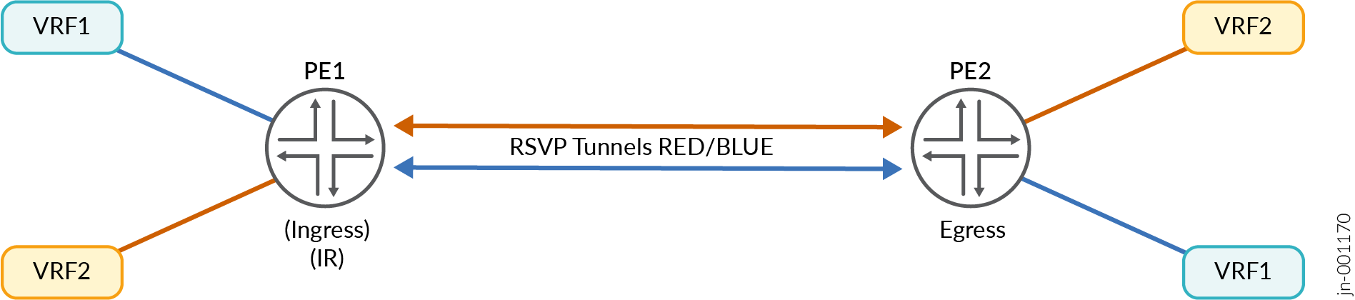
For example, in the illustration above, there are two sets of RSVP tunnels with names "red"
and "blue". You can further specify these names as a regular expression in the tunnel
configuration (be it inclusive or selective) to match the corresponding set of unicast
tunnels. When the regular expression of the unicast tunnel matches that of the RSVP tunnel
LSP in the inet.3 table, that specific LSP is selected for ingress replication. This is
applicable for both inclusive and selective PMSI. Use the
unicast-tunnel-name-regular-expression
configuration statement under the routing-instances provider-tunnel
ingress-replication hierarchy.
- To configure inclusive PMSI:
set routing-instances routing-instance-name provider-tunnel ingress-replication unicast-tunnel-name-regular-expression <reg-ex> - To configure selective PMSI:
set routing-instances routing-instance-name provider-tunnel selective group 228.1.1.1/32 source 0.0.0.0/0 ingress-replication unicast-tunnel-name-regular-expression
<reg-ex>
Configure a colored inet.3 table for Ingress Replication
By default, ingress replication uses the default inet.3 table to find the unicast tunnel to a tunnel leaf. Junos supports colored inet.3 tables for resolving BGP next hops, and they can also be used for ingress replication through unicast tunnels.
You can specify which RSVP tunnels are placed into specific colored inet.3 tables by using
the configuration statement
transport-class
under the routing-instances vrf provider-tunnel
ingress-replication hierarchy.
set routing-instances vrf provider-tunnel ingress-replication transport-class
<color>
Subsequently configure the MVPN tunnel for ingress replication to specify which corresponding colored inet.3 table to use.
Fine-tuning RSVP Tunnel Selection by Combining Regular Expressions with Colored Tables
By combining regular expressions with colored inet.3 tables, you can further fine-tune RSVP tunnel selection during ingress replication. Only RSVP tunnel names that match a specific regular expression and belong to a specific colored inet.3 table are selected, providing granular control over which provider tunnels are used to route multicast traffic over the core network towards egress PEs.
For example, there are four LSPs to the same ingress replication tunnel leaf named red1, red2, blue1 and blue2. They’re placed in red and blue colored inet.3 tables and the MVPN tunnel configuration for ingress replication is used to specify both a regular expression and the colored table to use. This ensures that only a tunnel in the specified table with the matching LSP name is used.
-
To configure inclusive PMSI:
set routing-instances vrf provider-tunnel ingress-replication transport-class <color> unicast-tunnel-name-regular-expression <reg-ex>
-
To configure selective PMSI:
set routing-instances vrf provider-tunnel selective group <group-address> source <source-address> ingress-replication transport-class <color> unicast-tunnel-name-regular-expression <reg-ex>
Configure a Root Address for MLDP Tunnels
IS-IS multi-instances can be used to create different topologies. By configuring the root address for MLDP tunnels, the lo.0 interface can be exported to different instances with different addresses. With this, egress PE devices can join tunnels in their corresponding topologies thereby achieving red/blue flow redundancy.
MVPN parses the configured root address and passes it to MLDP. In return, MLDP sends an MLDP FEC with different loopback addresses (as opposed to the default loopback) which is used by MVPN to advertise inclusive and selective tunnels via I-PMSI/S-PMSI routes. With different loopback addresses being exported into different instances, egress PE devices can join tunnels in its corresponding topologies.
Use the
root-address
configuration statement under the routing-instances provider tunnel
ldp-p2mp hierarchy.
set routing-instances vrf provider-tunnel ldp-p2mp root-address <root-address>
See Also
Controlling PIM Resources for Multicast VPNs Overview
A service provider network must protect itself from potential attacks from misconfigured or misbehaving customer edge (CE) devices and their associated VPN routing and forwarding (VRF) routing instances. Misbehaving CE devices can potentially advertise a large number of multicast routes toward a provider edge (PE) device, thereby consuming memory on the PE device and using other system resources in the network that are reserved for routes belonging to other VPNs.
To protect against potential misbehaving CE devices and VRF routing instances for specific multicast VPNs (MVPNs), you can control the following Protocol Independent Multicast (PIM) resources:
Limit the number of accepted PIM join messages for any-source groups (*,G) and source-specific groups (S,G).
Note how the device counts the PIM join messages:
Each (*,G) counts as one group toward the limit.
Each (S,G) counts as one group toward the limit.
Limit the number of PIM register messages received for a specific VRF routing instance. Use this configuration if the device is configured as a rendezvous point (RP) or has the potential to become an RP. When a source in a multicast network becomes active, the source’s designated router (DR) encapsulates multicast data packets into a PIM register message and sends them by means of unicast to the RP router.
Note how the device counts PIM register messages:
Each unique (S,G) join received by the RP counts as one group toward the configured register messages limit.
Periodic register messages sent by the DR for existing or already known (S,G) entries do not count toward the configured register messages limit.
Register messages are accepted until either the PIM register limit or the PIM join limit (if configured) is exceeded. Once either limit isreached, any new requests are dropped.
Limit the number of group-to-RP mappings allowed in a specific VRF routing instance. Use this configuration if the device is configured as an RP or has the potential to become an RP. This configuration can apply to devices configured for automatic RP announce and discovery (Auto-RP) or as a PIM bootstrap router. Every multicast device within a PIM domain must be able to map a particular multicast group address to the same RP. Both Auto-RP and the bootstrap router functionality are the mechanisms used to learn the set of group-to-RP mappings. Auto-RP is typically used in a PIM dense-mode deployment, and the bootstrap router is typically used in a PIM sparse-mode deployment.
Note:The group-to-RP mappings limit does not apply to static RP or embedded RP configurations.
Some important things to note about how the device counts group-to-RP mappings:
One group prefix mapped to five RPs counts as five group-to-RP mappings.
Five distinct group prefixes mapped to one RP count as five group-to-RP mappings.
Once the configured limits are reached, no new PIM join messages, PIM register messages, or group-to-RP mappings are accepted unless one of the following occurs:
You clear the current PIM join states by using the
clear pim joincommand. If you use this command on an RP configured for PIM register message limits, the register limit count is also restarted because the PIM join messages are unknown by the RP.Note:On the RP, you can also use the
clear pim registercommand to clear all of the PIM registers. This command is useful if the current PIM register count is greater than the newly configured PIM register limit. After you clear the PIM registers, new PIM register messages are received up to the configured limit.The traffic responsible for the excess PIM join messages and PIM register messages stops and is no longer present.
- CAUTION:
Never restart any of the software processes unless instructed to do so by a customer support engineer.
You restart the PIM routing process on the device. This restart clears all of the configured limits but disrupts routing and therefore requires a maintenance window for the change.
System Log Messages for PIM Resources
You can optionally configure a system log warning threshold for each of the PIM resources. With this configuration, you can generate and review system log messages to detect if an excessive number of PIM join messages, PIM register messages, or group-to-RP mappings have been received on the device. The system log warning thresholds are configured per PIM resource and are a percentage of the configured maximum limits of the PIM join messages, PIM register messages, and group-to-RP mappings. You can further specify a log interval for each configured PIM resource, which is the amount of time (in seconds) between the log messages.
The log messages convey when the configured limits have been exceeded, when the configured warning thresholds have been exceeded, and when the configured limits drop below the configured warning threshold. Table 1 describes the different types of PIM system messages that you might see depending on your system log warning and log interval configurations.
System Log Message |
Definition |
|---|---|
RPD_PIM_SG_THRESHOLD_EXCEED |
Records when the (S,G)/(*,G) routes exceed the configured warning threshold. |
RPD_PIM_REG_THRESH_EXCEED |
Records when the PIM registers exceed the configured warning threshold. |
RPD_PIM_GRP_RP_MAP_THRES_EXCEED |
Records when the group-to-RP mappings exceed the configured warning threshold. |
RPD_PIM_SG_LIMIT_EXCEED |
Records when the (S,G)/(*,G) routes exceed the configured limit, or when the configured log interval has been met and the routes exceed the configured limit. |
RPD_PIM_REGISTER_LIMIT_EXCEED |
Records when the PIM registers exceed the configured limit, or when the configured log interval has been met and the registers exceed the configured limit. |
RPD_PIM_GRP_RP_MAP_LIMIT_EXCEED |
Records when the group-to-RP mappings exceed the configured limit, or when the configured log interval has been met and the mapping exceeds the configured limit. |
RPD_PIM_SG_LIMIT_BELOW |
Records when the (S,G)/(*,G) routes drop below the configured limit and the configured log interval. |
RPD_PIM_REGISTER_LIMIT_BELOW |
Records when the PIM registers drop below the configured limit and the configured log interval. |
RPD_PIM_GRP_RP_MAP_LIMIT_BELOW |
Records when the group-to-RP mappings drop below the configured limit and the configured log interval. |
Example: Configuring PIM State Limits
This example shows how to set limits on the Protocol Independent Multicast (PIM) state information so that a service provider network can protect itself from potential attacks from misconfigured or misbehaving customer edge (CE) devices and their associated VPN routing and forwarding (VRF) routing instances.
Requirements
No special configuration beyond device initialization is required before configuring this example.
Overview
In this example, a multiprotocol BGP-based multicast VPN (next-generation MBGP MVPN) is configured with limits on the PIM state resources.
The sglimit maximum statement sets a limit for the
number of accepted (*,G) and (S,G) PIM join states received for the
vpn-1 routing instance.
The rp register-limit maximum statement configures
a limit for the number of PIM register messages received for the vpn-1
routing instance. You configure this statement on the rendezvuos point
(RP) or on all the devices that might become the RP.
The group-rp-mapping maximum statement configures
a limit for the number of group-to-RP mappings allowed in the vpn-1
routing instance.
For each configured PIM resource, the threshold statement
sets a percentage of the maximum limit at which to start generating
warning messages in the PIM log file.
For each configured PIM resource, the log-interval statement is an amount of time (in seconds) between system log message
generation.
Figure 3 shows the topology used in this example.
CLI Quick Configuration shows the configuration for all of the devices in Figure 3. The section Device PE1 below describes the steps for Device PE1.
Configuration
Procedure
CLI Quick Configuration
To quickly configure
this example, copy the following commands, paste them into a text
file, remove any line breaks, change any details necessary to match
your network configuration, and then copy and paste the commands into
the CLI at the [edit] hierarchy level.
Device CE1
set interfaces ge-1/2/0 unit 1 family inet address 10.1.1.1/30
set interfaces ge-1/2/0 unit 1 family mpls
set interfaces lo0 unit 1 family inet address 192.0.2.1/24
set protocols ospf area 0.0.0.0 interface lo0.1 passive
set protocols ospf area 0.0.0.0 interface ge-1/2/0.1
set protocols pim rp static address 203.0.113.1
set protocols pim interface all
set routing-options router-id 192.0.2.1
Device PE1
set interfaces ge-1/2/0 unit 2 family inet address 10.1.1.2/30
set interfaces ge-1/2/0 unit 2 family mpls
set interfaces ge-1/2/1 unit 5 family inet address 10.1.1.5/30
set interfaces ge-1/2/1 unit 5 family mpls
set interfaces vt-1/2/0 unit 2 family inet
set interfaces lo0 unit 2 family inet address 192.0.2.2/24
set interfaces lo0 unit 102 family inet address 203.0.113.1/24
set protocols mpls interface ge-1/2/1.5
set protocols bgp group ibgp type internal
set protocols bgp group ibgp local-address 192.0.2.2
set protocols bgp group ibgp family inet-vpn any
set protocols bgp group ibgp family inet-mvpn signaling
set protocols bgp group ibgp neighbor 192.0.2.4
set protocols bgp group ibgp neighbor 192.0.2.5
set protocols ospf area 0.0.0.0 interface lo0.2 passive
set protocols ospf area 0.0.0.0 interface ge-1/2/1.5
set protocols ldp interface ge-1/2/1.5
set protocols ldp p2mp
set policy-options policy-statement parent_vpn_routes from protocol bgp
set policy-options policy-statement parent_vpn_routes then accept
set routing-instances vpn-1 instance-type vrf
set routing-instances vpn-1 interface ge-1/2/0.2
set routing-instances vpn-1 interface vt-1/2/0.2
set routing-instances vpn-1 interface lo0.102
set routing-instances vpn-1 route-distinguisher 100:100
set routing-instances vpn-1 provider-tunnel ldp-p2mp
set routing-instances vpn-1 vrf-target target:1:1
set routing-instances vpn-1 protocols ospf export parent_vpn_routes
set routing-instances vpn-1 protocols ospf area 0.0.0.0 interface lo0.102 passive
set routing-instances vpn-1 protocols ospf area 0.0.0.0 interface ge-1/2/0.2
set routing-instances vpn-1 protocols pim sglimit family inet maximum 100
set routing-instances vpn-1 protocols pim sglimit family inet threshold 70
set routing-instances vpn-1 protocols pim sglimit family inet log-interval 10
set routing-instances vpn-1 protocols pim rp register-limit family inet maximum 100
set routing-instances vpn-1 protocols pim rp register-limit family inet threshold 80
set routing-instances vpn-1 protocols pim rp register-limit family inet log-interval 10
set routing-instances vpn-1 protocols pim rp group-rp-mapping family inet maximum 100
set routing-instances vpn-1 protocols pim rp group-rp-mapping family inet threshold 80
set routing-instances vpn-1 protocols pim rp group-rp-mapping family inet log-interval 10
set routing-instances vpn-1 protocols pim rp static address 203.0.113.1
set routing-instances vpn-1 protocols pim interface ge-1/2/0.2 mode sparse
set routing-instances vpn-1 protocols mvpn
set routing-options router-id 192.0.2.2
set routing-options autonomous-system 1001
Device P
set interfaces ge-1/2/0 unit 6 family inet address 10.1.1.6/30
set interfaces ge-1/2/0 unit 6 family mpls
set interfaces ge-1/2/1 unit 9 family inet address 10.1.1.9/30
set interfaces ge-1/2/1 unit 9 family mpls
set interfaces ge-1/2/2 unit 13 family inet address 10.1.1.13/30
set interfaces ge-1/2/2 unit 13 family mpls
set interfaces lo0 unit 3 family inet address 192.0.2.3/24
set protocols mpls interface ge-1/2/0.6
set protocols mpls interface ge-1/2/1.9
set protocols mpls interface ge-1/2/2.13
set protocols ospf area 0.0.0.0 interface lo0.3 passive
set protocols ospf area 0.0.0.0 interface ge-1/2/0.6
set protocols ospf area 0.0.0.0 interface ge-1/2/1.9
set protocols ospf area 0.0.0.0 interface ge-1/2/2.13
set protocols ldp interface ge-1/2/0.6
set protocols ldp interface ge-1/2/1.9
set protocols ldp interface ge-1/2/2.13
set protocols ldp p2mp
set routing-options router-id 192.0.2.3
Device PE2
set interfaces ge-1/2/0 unit 10 family inet address 10.1.1.10/30
set interfaces ge-1/2/0 unit 10 family mpls
set interfaces ge-1/2/1 unit 17 family inet address 10.1.1.17/30
set interfaces ge-1/2/1 unit 17 family mpls
set interfaces vt-1/2/0 unit 4 family inet
set interfaces lo0 unit 4 family inet address 192.0.2.4/24
set interfaces lo0 unit 104 family inet address 203.0.113.4/24
set protocols mpls interface ge-1/2/0.10
set protocols bgp group ibgp type internal
set protocols bgp group ibgp local-address 192.0.2.4
set protocols bgp group ibgp family inet-vpn any
set protocols bgp group ibgp family inet-mvpn signaling
set protocols bgp group ibgp neighbor 192.0.2.2
set protocols bgp group ibgp neighbor 192.0.2.5
set protocols ospf area 0.0.0.0 interface lo0.4 passive
set protocols ospf area 0.0.0.0 interface ge-1/2/0.10
set protocols ldp interface ge-1/2/0.10
set protocols ldp p2mp
set policy-options policy-statement parent_vpn_routes from protocol bgp
set policy-options policy-statement parent_vpn_routes then accept
set routing-instances vpn-1 instance-type vrf
set routing-instances vpn-1 interface vt-1/2/0.4
set routing-instances vpn-1 interface ge-1/2/1.17
set routing-instances vpn-1 interface lo0.104
set routing-instances vpn-1 route-distinguisher 100:100
set routing-instances vpn-1 vrf-target target:1:1
set routing-instances vpn-1 protocols ospf export parent_vpn_routes
set routing-instances vpn-1 protocols ospf area 0.0.0.0 interface lo0.104 passive
set routing-instances vpn-1 protocols ospf area 0.0.0.0 interface ge-1/2/1.17
set routing-instances vpn-1 protocols pim rp group-rp-mapping family inet maximum 100
set routing-instances vpn-1 protocols pim rp group-rp-mapping family inet threshold 80
set routing-instances vpn-1 protocols pim rp group-rp-mapping family inet log-interval 10
set routing-instances vpn-1 protocols pim rp static address 203.0.113.1
set routing-instances vpn-1 protocols pim interface ge-1/2/1.17 mode sparse
set routing-instances vpn-1 protocols mvpn
set routing-options router-id 192.0.2.4
set routing-options autonomous-system 1001
Device PE3
set interfaces ge-1/2/0 unit 14 family inet address 10.1.1.14/30
set interfaces ge-1/2/0 unit 14 family mpls
set interfaces ge-1/2/1 unit 21 family inet address 10.1.1.21/30
set interfaces ge-1/2/1 unit 21 family mpls
set interfaces vt-1/2/0 unit 5 family inet
set interfaces lo0 unit 5 family inet address 192.0.2.5/24
set interfaces lo0 unit 105 family inet address 203.0.113.5/24
set protocols mpls interface ge-1/2/0.14
set protocols bgp group ibgp type internal
set protocols bgp group ibgp local-address 192.0.2.5
set protocols bgp group ibgp family inet-vpn any
set protocols bgp group ibgp family inet-mvpn signaling
set protocols bgp group ibgp neighbor 192.0.2.2
set protocols bgp group ibgp neighbor 192.0.2.4
set protocols ospf area 0.0.0.0 interface lo0.5 passive
set protocols ospf area 0.0.0.0 interface ge-1/2/0.14
set protocols ldp interface ge-1/2/0.14
set protocols ldp p2mp
set policy-options policy-statement parent_vpn_routes from protocol bgp
set policy-options policy-statement parent_vpn_routes then accept
set routing-instances vpn-1 instance-type vrf
set routing-instances vpn-1 interface vt-1/2/0.5
set routing-instances vpn-1 interface ge-1/2/1.21
set routing-instances vpn-1 interface lo0.105
set routing-instances vpn-1 route-distinguisher 100:100
set routing-instances vpn-1 vrf-target target:1:1
set routing-instances vpn-1 protocols ospf export parent_vpn_routes
set routing-instances vpn-1 protocols ospf area 0.0.0.0 interface lo0.105 passive
set routing-instances vpn-1 protocols ospf area 0.0.0.0 interface ge-1/2/1.21
set routing-instances vpn-1 protocols pim rp static address 203.0.113.1
set routing-instances vpn-1 protocols pim interface ge-1/2/1.21 mode sparse
set routing-instances vpn-1 protocols mvpn
set routing-options router-id 192.0.2.5
set routing-options autonomous-system 1001
Device CE2
set interfaces ge-1/2/0 unit 18 family inet address 10.1.1.18/30
set interfaces ge-1/2/0 unit 18 family mpls
set interfaces lo0 unit 6 family inet address 192.0.2.6/24
set protocols sap listen 192.168.0.0
set protocols ospf area 0.0.0.0 interface lo0.6 passive
set protocols ospf area 0.0.0.0 interface ge-1/2/0.18
set protocols pim rp static address 203.0.113.1
set protocols pim interface all
set routing-options router-id 192.0.2.6
Device CE3
set interfaces ge-1/2/0 unit 22 family inet address 10.1.1.22/30
set interfaces ge-1/2/0 unit 22 family mpls
set interfaces lo0 unit 7 family inet address 192.0.2.7/24
set protocols ospf area 0.0.0.0 interface lo0.7 passive
set protocols ospf area 0.0.0.0 interface ge-1/2/0.22
set protocols pim rp static address 203.0.113.1
set protocols pim interface all
set routing-options router-id 192.0.2.7
Step-by-Step Procedure
The following example requires you to navigate various levels in the configuration hierarchy. For information about navigating the CLI, see Using the CLI Editor in Configuration Mode in the CLI User Guide.
To configure PIM state limits:
Configure the network interfaces.
[edit interfaces]
user@PE1# set ge-1/2/0 unit 2 family inet address 10.1.1.2/30
user@PE1# set ge-1/2/0 unit 2 family mpls
user@PE1# set ge-1/2/1 unit 5 family inet address 10.1.1.5/30
user@PE1# set ge-1/2/1 unit 5 family mpls
user@PE1# set vt-1/2/0 unit 2 family inet
user@PE1# set lo0 unit 2 family inet address 192.0.2.2/24
user@PE1# set lo0 unit 102 family inet address 203.0.113.1/24
Configure MPLS on the core-facing interface.
[edit protocols mpls]
user@PE1# set interface ge-1/2/1.5
Configure internal BGP (IBGP) on the main router.
The IBGP neighbors are the other PE devices.
[edit protocols bgp group ibgp]
user@PE1# set type internal
user@PE1# set local-address 192.0.2.2
user@PE1# set family inet-vpn any
user@PE1# set family inet-mvpn signaling
user@PE1# set neighbor 192.0.2.4
user@PE1# set neighbor 192.0.2.5
Configure OSPF on the main router.
[edit protocols ospf area 0.0.0.0]
user@PE1# set interface lo0.2 passive
user@PE1# set interface ge-1/2/1.5
Configure a signaling protocol (RSVP or LDP) on the main router.
[edit protocols ldp]
user@PE1# set interface ge-1/2/1.5
user@PE1# set p2mp
Configure the BGP export policy.
[edit policy-options policy-statement parent_vpn_routes]
user@PE1# set from protocol bgp
user@PE1# set then accept
Configure the routing instance.
The customer-facing interfaces and the BGP export policy are referenced in the routing instance.
[edit routing-instances vpn-1]
user@PE1# set instance-type vrf
user@PE1# set interface ge-1/2/0.2
user@PE1# set interface vt-1/2/0.2
user@PE1# set interface lo0.102
user@PE1# set route-distinguisher 100:100
user@PE1# set provider-tunnel ldp-p2mp
user@PE1# set vrf-target target:1:1
user@PE1# set protocols ospf export parent_vpn_routes
user@PE1# set protocols ospf area 0.0.0.0 interface lo0.102 passive
user@PE1# set protocols ospf area 0.0.0.0 interface ge-1/2/0.2
user@PE1# set protocols pim rp static address 203.0.113.1
user@PE1# set protocols pim interface ge-1/2/0.2 mode sparse
user@PE1# set protocols mvpn
Configure the PIM state limits.
[edit routing-instances vpn-1 protocols pim]
user@PE1# set sglimit family inet maximum 100
user@PE1# set sglimit family inet threshold 70
user@PE1# set sglimit family inet log-interval 10
user@PE1# set rp register-limit family inet maximum 100
user@PE1# set rp register-limit family inet threshold 80
user@PE1# set rp register-limit family inet log-interval 10
user@PE1# set rp group-rp-mapping family inet maximum 100
user@PE1# set rp group-rp-mapping family inet threshold 80
user@PE1# set rp group-rp-mapping family inet log-interval 10
Configure the router ID and AS number.
[edit routing-options]
user@PE1# set router-id 192.0.2.2
user@PE1# set autonomous-system 1001
Results
From configuration mode, confirm your configuration
by entering the show interfaces, show protocols, show policy-options, show routing-instances, and show routing-options commands. If the output does
not display the intended configuration, repeat the configuration instructions
in this example to correct it.
user@PE1# show interfaces
ge-1/2/0 {
    unit 2 {
        family inet {
            address 10.1.1.2/30;
        }
        family mpls;
    }
}
ge-1/2/1 {
    unit 5 {
        family inet {
            address 10.1.1.5/30;
        }
        family mpls;
    }
}
vt-1/2/0 {
    unit 2 {
        family inet;
    }
}
lo0 {
    unit 2 {
        family inet {
            address 192.0.2.2/24;
        }
    }
    unit 102 {
        family inet {
            address 203.0.113.1/24;
        }
    }
}
user@PE1# show protocols
mpls {
    interface ge-1/2/1.5;
}
bgp {
    group ibgp {
        type internal;
        local-address 192.0.2.2;
        family inet-vpn {
            any;
        }
        family inet-mvpn {
            signaling;
        }
        neighbor 192.0.2.4;
        neighbor 192.0.2.5;
    }
}
ospf {
    area 0.0.0.0 {
        interface lo0.2 {
            passive;
        }
        interface ge-1/2/1.5;
    }
}
ldp {
    interface ge-1/2/1.5;
    p2mp;
}
user@PE1# show policy-options
policy-statement parent_vpn_routes {
    from protocol bgp;
    then accept;
}
user@PE1# show routing-instances
vpn-1 {
    instance-type vrf;
    interface ge-1/2/0.2;
    interface vt-1/2/0.2;
    interface lo0.102;
    route-distinguisher 100:100;
    provider-tunnel {
        ldp-p2mp;
    }
    vrf-target target:1:1;
    protocols {
        ospf {
            export parent_vpn_routes;
            area 0.0.0.0 {
                interface lo0.102 {
                    passive;
                }
                interface ge-1/2/0.2;
            }
        }
        pim {
            sglimit {
                family inet {
                    maximum 100;
                    threshold 70;
                    log-interval 10;
                }
            }
            rp {
                register-limit {
                    family inet {
                        maximum 100;
                        threshold 80;
                        log-interval 10;
                    }
                }
                group-rp-mapping {
                    family inet {
                        maximum 100;
                        threshold 80;
                        log-interval 10;
                    }
                }
                static {
                    address 203.0.113.1;
                }
            }
            interface ge-1/2/0.2 {
                mode sparse;
            }
        }
        mvpn;
    }
}
user@PE1# show routing-options
router-id 192.0.2.2;
autonomous-system 1001;
If you are done configuring the device, enter commit from configuration mode.
Verification
Confirm that the configuration is working properly.
Monitoring the PIM State Information
Purpose
Verify that the counters are set as expected and are not exceeding the configured limits.
Action
From operational mode, enter the show pim statistics command.
user@PE1> show pim statistics instance vpn-1
PIM Message type        Received       Sent  Rx errors
V2 Hello                     393        390          0
...
V4 (S,G) Maximum                            100
V4 (S,G) Accepted                             0
V4 (S,G) Threshold                           70
V4 (S,G) Log Interval                        10
V4 (grp-prefix, RP) Maximum                 100
V4 (grp-prefix, RP) Accepted                  0
V4 (grp-prefix, RP) Threshold                80
V4 (grp-prefix, RP) Log Interval             10
V4 Register Maximum                         100
V4 Register Accepted                          0
V4 Register Threshold                        80
V4 Register Log Interval                     10
Meaning
The V4 (S,G) Maximum field shows the maximum number of (S,G) IPv4 multicast routes accepted for the VPN routing instance. If this number is met, additional (S,G) entries are not accepted.
The V4 (S,G) Accepted field shows the number of accepted (S,G) IPv4 multicast routes.
The V4 (S,G) Threshold field shows the threshold at which a warning message is logged (percentage of the maximum number of (S,G) IPv4 multicast routes accepted by the device).
The V4 (S,G) Log Interval field shows the time (in seconds) between consecutive log messages.
The V4 (grp-prefix, RP) Maximum field shows the maximum number of group-to-rendezvous point (RP) IPv4 multicast mappings accepted for the VRF routing instance. If this number is met, additional mappings are not accepted.
The V4 (grp-prefix, RP) Accepted field shows the number of accepted group-to-RP IPv4 multicast mappings.
The V4 (grp-prefix, RP) Threshold field shows the threshold at which a warning message is logged (percentage of the maximum number of group-to-RP IPv4 multicast mappings accepted by the device).
The V4 (grp-prefix, RP) Log Interval field shows the time (in seconds) between consecutive log messages.
The V4 Register Maximum field shows the maximum number of IPv4 PIM registers accepted for the VRF routing instance. If this number is met, additional PIM registers are not accepted. You configure the register limits on the RP.
The V4 Register Accepted field shows the number of accepted IPv4 PIM registers.
The V4 Register Threshold field shows the threshold at which a warning message is logged (percentage of the maximum number of IPv4 PIM registers accepted by the device).
The V4 Register Log Interval field shows the time (in seconds) between consecutive log messages.
Understanding Wildcards to Configure Selective Point-to-Multipoint LSPs for an MBGP MVPN
Selective LSPs are also referred to as selective provider tunnels. Selective provider tunnels carry traffic from some multicast groups in a VPN and extend only to the PE routers that have receivers for these groups. You can configure a selective provider tunnel for group prefixes and source prefixes, or you can use wildcards for the group and source, as described in the Internet draft draft-rekhter-mvpn-wildcard-spmsi-01.txt, Use of Wildcard in S-PMSI Auto-Discovery Routes.
The following sections describe the scenarios and special considerations when you use wildcards for selective provider tunnels.
- About S-PMSI
- Scenarios for Using Wildcard S-PMSI
- Types of Wildcard S-PMSI
- Differences Between Wildcard S-PMSI and (S,G) S-PMSI
- Wildcard (*,*) S-PMSI and PIM Dense Mode
- Wildcard (*,*) S-PMSI and PIM-BSR
- Wildcard Source and the 0.0.0.0/0 Source Prefix
About S-PMSI
The provider multicast service interface (PMSI) is a BGP tunnel attribute that contains the tunnel ID used by the PE router for transmitting traffic through the core of the provider network. A selective PMSI (S-PMSI) autodiscovery route advertises binding of a given MVPN customer multicast flow to a particular provider tunnel. The S-PMSI autodiscovery route advertised by the ingress PE router contains /32 IPv4 or /128 IPv6 addresses for the customer source and the customer group derived from the source-tree customer multicast route.
Figure 4 shows a simple MVPN topology. The ingress router, PE1, originates the S-PMSI autodiscovery route. The egress routers, PE2 and PE3, have join state as a result of receiving join messages from CE devices that are not shown in the topology. In response to the S-PMSI autodiscovery route advertisement sent by PE1, PE2, and PE3, elect whether or not to join the tunnel based on the join state. The selective provider tunnel configuration is configured in a VRF instance on PE1.
The MVPN mode configuration (RPT-SPT or SPT-only) is configured on all three PE routers for all VRFs that make up the VPN. If you omit the MVPN mode configuration, the default mode is SPT-only.
Scenarios for Using Wildcard S-PMSI
A wildcard S-PMSI has the source or the group (or both the source and the group) field set to the wildcard value of 0.0.0.0/0 and advertises binding of multiple customer multicast flows to a single provider tunnel in a single S-PMSI autodiscovery route.
The scenarios under which you might configure a wildcard S-PMSI are as follows:
When the customer multicast flows are PIM-SM in ASM-mode flows. In this case, a PE router connected to an MVPN customer's site that contains the customer's RP (C-RP) could bind all the customer multicast flows traveling along a customer's RPT tree to a single provider tunnel.
When a PE router is connected to an MVPN customer’s site that contains multiple sources, all sending to the same group.
When the customer multicast flows are PIM-bidirectional flows. In this case, a PE router could bind to a single provider tunnel all the customer multicast flows for the same group that have been originated within the sites of a given MVPN connected to that PE, and advertise such binding in a single S-PMSI autodiscovery route.
When the customer multicast flows are PIM-SM in SSM-mode flows. In this case, a PE router could bind to a single provider tunnel all the customer multicast flows coming from a given source located in a site connected to that PE router.
When you want to carry in the provider tunnel all the customer multicast flows originated within the sites of a given MVPN connected to a given PE router.
Types of Wildcard S-PMSI
The following types of wildcard S-PMSI are supported:
A (*,G) S-PMSI matches all customer multicast routes that have the group address. The customer source address in the customer multicast route can be any address, including 0.0.0.0/0 for shared-tree customer multicast routes. A (*, C-G) S-PMSI autodiscovery route is advertised with the source field set to 0 and the source address length set to 0. The multicast group address for the S-PMSI autodiscovery route is derived from the customer multicast joins.
A (*,*) S-PMSI matches all customer multicast routes. Any customer source address and any customer group address in a customer multicast route can be bound to the (*,*) S-PMSI. The S-PMSI autodiscovery route is advertised with the source address and length set to 0 and the group address and length set 0. The remaining fields in the S-PMSI autodiscovery route follow the same rule as (C-S, C-G) S-PMSI, as described in section 12.1 of the BGP-MVPN draft (draft-ietf-l3vpn-2547bis-mcast-bgp-00.txt).
Differences Between Wildcard S-PMSI and (S,G) S-PMSI
For dynamic provider tunnels, each customer multicast stream is bound to a separate provider tunnel, and each tunnel is advertised by a separate S-PMSI autodiscovery route. For static LSPs, multiple customer multicast flows are bound to a single provider tunnel by having multiple S-PMSI autodiscovery routes advertise the same provider tunnel.
When you configure a wildcard (*,G) or (*,*) S-PMSI, one or more matching customer multicast routes share a single S-PMSI. All customer multicast routes that have a matching source and group address are bound to the same (*,G) or (*,*) S-PMSI and share the same tunnel. The (*,G) or (*,*) S-PMSI is established when the first matching remote customer multicast join message is received in the ingress PE router, and deleted when the last remote customer multicast join is withdrawn from the ingress PE router. Sharing a single S-PMSI autodiscovery route improves control plane scalability.
Wildcard (*,*) S-PMSI and PIM Dense Mode
For (S,G) and (*,G) S-PMSI autodiscovery routes in PIM dense mode (PIM-DM), all downstream PE routers receive PIM-DM traffic. If a downstream PE router does not have receivers that are interested in the group address, the PE router instantiates prune state and stops receiving traffic from the tunnel.
Now consider what happens for (*,*) S-PMSI autodiscovery routes. If the PIM-DM traffic is not bound by a longer matching (S,G) or (*,G) S-PMSI, it is bound to the (*,*) S-PMSI. As is always true for dense mode, PIM-DM traffic is flooded to downstream PE routers over the provider tunnel regardless of the customer multicast join state. Because there is no group information in the (*,*) S-PMSI autodiscovery route, egress PE routers join a (*,*) S-PMSI tunnel if there is any configuration on the egress PE router indicating interest in PIM-DM traffic.
Interest in PIM-DM traffic is indicated if the egress PE router has one of the following configurations in the VRF instance that corresponds to the instance that imports the S-PMSI autodiscovery route:
At least one interface is configured in dense mode at the
[edit routing-instances instance-name protocols pim interface]hierarchy level.At least one group is configured as a dense-mode group at the
[edit routing-instances instance-name protocols pim dense-groups group-address]hierarchy level.
Wildcard (*,*) S-PMSI and PIM-BSR
For (S,G) and (*,G) S-PMSI autodiscovery routes in PIM bootstrap router (PIM-BSR) mode, an ingress PE router floods the PIM bootstrap message (BSM) packets over the provider tunnel to all egress PE routers. An egress PE router does not join the tunnel unless the message has the ALL-PIM-ROUTERS group. If the message has this group, the egress PE router joins the tunnel, regardless of the join state. The group field in the message determines the presence or absence of the ALL-PIM-ROUTERS address.
Now consider what would happen for (*,*) S-PMSI autodiscovery routes used with PIM-BSR mode. If the PIM BSM packets are not bound by a longer matching (S,G) or (*,G) S-PMSI, they are bound to the (*,*) S-PMSI. As is always true for PIM-BSR, BSM packets are flooded to downstream PE routers over the provider tunnel to the ALL-PIM-ROUTERS destination group. Because there is no group information in the (*,*) S-PMSI autodiscovery route, egress PE routers always join a (*,*) S-PMSI tunnel. Unlike PIM-DM, the egress PE routers might have no configuration suggesting use of PIM-BSR as the RP discovery mechanism in the VRF instance. To prevent all egress PE routers from always joining the (*,*) S-PMSI tunnel, the (*,*) wildcard group configuration must be ignored.
This means that if you configure PIM-BSR, a wildcard-group S-PMSI can be configured for all other group addresses. The (*,*) S-PMSI is not used for PIM-BSR traffic. Either a matching (*,G) or (S,G) S-PMSI (where the group address is the ALL-PIM-ROUTERS group) or an inclusive provider tunnel is needed to transmit data over the provider core. For PIM-BSR, the longest-match lookup is (S,G), (*,G), and the inclusive provider tunnel, in that order. If you do not configure an inclusive tunnel for the routing instance, you must configure a (*,G) or (S,G) selective tunnel. Otherwise, the data is dropped. This is because PIM-BSR functions like PIM-DM, in that traffic is flooded to downstream PE routers over the provider tunnel regardless of the customer multicast join state. However, unlike PIM-DM, the egress PE routers might have no configuration to indicate interest or noninterest in PIM-BSR traffic.
Wildcard Source and the 0.0.0.0/0 Source Prefix
You can configure a 0.0.0.0/0 source prefix and a wildcard source under the same group prefix in a selective provider tunnel. For example, the configuration might look as follows:
routing-instances {
    vpna {
        provider-tunnel {
            selective {
                group 203.0.113.0/24 {
                    source 0.0.0.0/0 {
                        rsvp-te {
                            label-switched-path-template {
                                sptnl3;
                            }
                        }
                    }
                    wildcard-source {
                        rsvp-te {
                            label-switched-path-template {
                                sptnl2;
                            }
                            static-lsp point-to-multipoint-lsp-name;
                        }
                        threshold-rate kbps;
                    }
                }
            }
        }
    }
}
The functions of the source 0.0.0.0/0 and wildcard-source configuration statements are different. The 0.0.0.0/0 source prefix
only matches (C-S, C-G) customer multicast join messages and triggers
(C-S, C-G) S-PMSI autodiscovery routes derived from the customer multicast
address. Because all (C-S, C-G) join messages are matched by the 0.0.0.0/0
source prefix in the matching group, the wildcard source S-PMSI is
used only for (*,C-G) customer multicast join messages. In the absence
of a configured 0.0.0.0/0 source prefix, the wildcard source matches
(C-S, C-G) and (*,C-G) customer multicast join messages. In the example,
a join message for (10.0.1.0/24, 203.0.113.0/24) is bound to sptnl3. A join message for (*, 203.0.113.0/24) is bound to sptnl2.
Configuring a Selective Provider Tunnel Using Wildcards
When you configure a selective provider tunnel for MBGP MVPNs (also referred to as next-generation Layer 3 multicast VPNs), you can use wildcards for the multicast group and source address prefixes. Using wildcards enables a PE router to use a single route to advertise the binding of multiple multicast streams of a given MVPN customer to a single provider's tunnel, as described in https://tools.ietf.org/html/draft-rekhter-mvpn-wildcard-spmsi-00 .
Sharing a single route improves control plane scalability because it reduces the number of S-PMSI autodiscovery routes.
To configure a selective provider tunnel using wildcards:
Example: Configuring Selective Provider Tunnels Using Wildcards
With the (*,G) and (*,*) S-PMSI, a customer multicast join message can match more than one S-PMSI. In this case, a customer multicast join message is bound to the longest matching S-PMSI. The longest match is a (S,G) S-PMSI, followed by a (*,G) S-PMSI and a (*,*) S-PMSI, in that order.
Consider the following configuration:
routing-instances {
    vpna {
        provider-tunnel {
            selective {
                wildcard-group-inet {
                    wildcard-source {
                        rsvp-te {
                            label-switched-path-template {
                                sptnl1;
                            }
                        }
                    }
                }
                group 203.0.113.0/24 {
                    wildcard-source {
                        rsvp-te {
                            label-switched-path-template {
                                sptnl2;
                            }
                        }
                    }
                    source 10.1.1/24 {
                        rsvp-te {
                            label-switched-path-template {
                                sptnl3;
                            }
                        }
                    }
                }
            }
        }
    }
}
For this configuration, the longest-match rule works as follows:
A customer multicast (10.1.1.1, 203.0.113.1) join message is bound to the sptnl3 S-PMSI autodiscovery route.
A customer multicast (10.2.1.1, 203.0.113.1) join message is bound to the sptnl2 S-PMSI autodiscovery route.
A customer multicast (10.1.1.1, 203.1.113.1) join message is bound to the sptnl1 S-PMSI autodiscovery route.
When more than one customer multicast route is bound to the same wildcard S-PMSI, only one S-PMSI autodiscovery route is created. An egress PE router always uses the same matching rules as the ingress PE router that advertises the S-PMSI autodiscovery route. This ensures consistent customer multicast mapping on the ingress and the egress PE routers.
Configuring NLRI Parameters for an MBGP MVPN
To enable VPN signaling where multiprotocol BGP carries
multicast VPN NLRI for the IPv4 address family, include the family
inet-mvpn statement:
inet-mvpn {
    signaling {
        accepted-prefix-limit {
            maximum number;
            teardown percentage {
                idle-timeout (forever | minutes);
            }
        }
        loops number;
        prefix-limit {
            maximum number;
            teardown percentage {
                idle-timeout (forever | minutes);
            }
        }
    }
}
To enable VPN signaling where multiprotocol BGP carries multicast
VPN NLRI for the IPv6 address family, include the family inet6-mvpn statement:
inet6-mvpn {
    signaling {
        accepted-prefix-limit {
            maximum number;
            teardown percentage {
                idle-timeout (forever | minutes);
            }
        }
        loops number
        prefix-limit {
            maximum number;
            teardown percentage {
                idle-timeout (forever | minutes);
            }
        }
    }
}