高度なセキュリティとデータセンターの相互接続構成
これらの例を使用して、集約されたスパインデータセンターアーキテクチャで高度なセキュリティとDCIを設定します。
テナント間トラフィックの高度なセキュリティの設定
SRXシリーズは、テナント間トラフィックに高度なセキュリティサービスを提供できる次世代ファイアウォールです。このセクションを使用して、SRXシャーシクラスターを介してDC1のJNPR_1とJNPR_2間のテナント間トラフィックをルーティングします。
必要条件
EVPNマルチホーミングを使用して折りたたみ式スパインを構成する方法で構成したデバイス。
SRXシャーシクラスターがすでに設定され、実行されている必要があります。SRXシャーシ クラスタの有効化の詳細については、 SRXシリーズ デバイスでのシャーシ クラスタリングの設定 を参照してください。
概要
シャーシクラスター内のSRXシリーズファイアウォールは、単一のデバイスとして動作し、デバイス、インターフェイス、およびサービスレベルの冗長性を提供します。このセクションでは、シャーシ クラスタをゾーンに分割し、正しいトラフィックがセキュリティ デバイスを介してルーティングされるようにルーティング ポリシーを設定します。
位相幾何学
図 1に示すように、両方のスパインスイッチが両方のSRXノードに物理的に接続されています。
 の物理トポロジー
この例は、SRX345デバイスに基づいています。HAクラスタに配置されると、ノード1のインターフェイスはFPCスロット5に関連付けられます。つまり、ノード1に示されているge-0/0/11インターフェイスは、クラスターが形成されると、実際にはge-5-0/11として設定されます。HAクラスタ内のノード1のFPC番号は、SRXモデルのタイプによって異なる場合があります。
Reth1は、SRXクラスター内の論理インターフェイスです。これは、SRXクラスターのノードの1つでアクティブです。SRXデバイスとスパインスイッチ間のプライマリノードまたは相互接続リンクに障害が発生した場合、Reth1はセカンダリノードにフェイルオーバーします。 図 2 は、SRX デバイスとスパイン スイッチ間の論理インターフェイスを示しています。
 のオーバーレイトポロジー
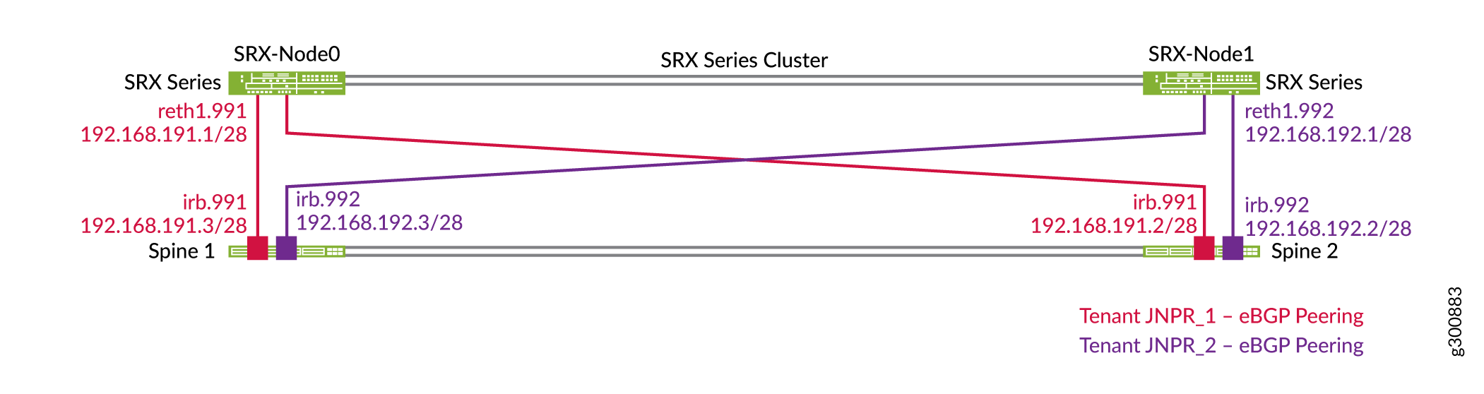
図3に示すように、各スパインスイッチは、各ルーティング インスタンスまたはテナントのSRXクラスターと個別のEBGPピアリングを確立します。たとえば、スパイン1には、SRXクラスターとのピアリングが2つあり、各ルーティング インスタンスに1つずつあります(JNPR_1とJNPR_2)。Reth1.991は、スパインスイッチ上のJNPR_1ルーティング インスタンスとピアリングし、JNPR_1セキュリティゾーンに属します。Reth1.992は、スパインスイッチ上のJNPR_2ルーティング インスタンスとピアリングし、JNPR_2セキュリティゾーンに属します。
SRXシリーズファイアウォールは、すべてのプレフィックス(例えば、192.168.0.0/16)をカバーするサマリールートをアドバタイズします。スパインスイッチは、各ルーティング インスタンスで特定のサブネットをアドバタイズします。
 を持つSRXクラスターのトポロジー
インターフェイスの設定
SRXデバイスを設定する
手順
SRX デバイス上の論理インターフェイスのグループを設定します。
set chassis cluster reth-count 3
set chassis cluster redundancy-group 0 node 0 priority 100
set chassis cluster redundancy-group 0 node 1 priority 1
set chassis cluster redundancy-group 1 node 0 priority 200
set chassis cluster redundancy-group 1 node 1 priority 100
set chassis cluster redundancy-group 1 preempt
set chassis cluster redundancy-group 1 interface-monitor ge-0/0/11 weight 255
set chassis cluster redundancy-group 1 interface-monitor ge-0/0/12 weight 255
set chassis cluster redundancy-group 1 interface-monitor ge-5/0/11 weight 255
set chassis cluster redundancy-group 1 interface-monitor ge-5/0/12 weight 255
論理インターフェイスを設定します。Reth1は、SRXクラスター上のタグ付きレイヤー3インターフェイスです。Reth1.991は、スパインスイッチ上のJNPR_1ルーティング インスタンスとピアリングします。Reth1.992は、スパインスイッチ上のJNPR_2ルーティング インスタンスとピアリングします。
set interfaces reth1 vlan-tagging
set interfaces reth1 redundant-ether-options redundancy-group 1
set interfaces reth1 redundant-ether-options lacp active
set interfaces reth1 redundant-ether-options lacp periodic fast
set interfaces reth1 unit 991 description "Spine Interconnect for JNPR_1"
set interfaces reth1 unit 991 vlan-id 991
set interfaces reth1 unit 991 family inet address 192.168.191.1/28

set interfaces reth1 unit 992 description "Spine Interconnect for JNPR_2"
set interfaces reth1 unit 992 vlan-id 992
set interfaces reth1 unit 992 family inet address 192.168.192.1/28

set interfaces ge-0/0/11 description "To Spine1 | ge-0/0/10"
set interfaces ge-0/0/11 gigether-options no-auto-negotiation
set interfaces ge-0/0/11 gigether-options redundant-parent reth1

set interfaces ge-5/0/11 description "To Spine1 | ge-0/0/11"
set interfaces ge-5/0/11 gigether-options no-auto-negotiation
set interfaces ge-5/0/11 gigether-options redundant-parent reth1

set interfaces ge-0/0/12 description "To Spine2 | ge-0/0/10"
set interfaces ge-0/0/12 gigether-options no-auto-negotiation
set interfaces ge-0/0/12 gigether-options redundant-parent reth1

set interfaces ge-5/0/12 description "To Spine2 | ge-0/0/11"
set interfaces ge-5/0/12 gigether-options no-auto-negotiation
set interfaces ge-5/0/12 gigether-options redundant-parent reth1
論理インターフェイスを個別のセキュリティゾーンに配置します。Reth1.991 は JNPR_1 セキュリティ ゾーンに属し、Reth1.992 は JNPR_2 セキュリティ ゾーンに属します。
set security zones security-zone JNPR_1-Zone host-inbound-traffic system-services ping
set security zones security-zone JNPR_1-Zone host-inbound-traffic protocols bgp
set security zones security-zone JNPR_1-Zone interfaces reth1.991

set security zones security-zone JNPR_2-Zone host-inbound-traffic system-services ping
set security zones security-zone JNPR_2-Zone host-inbound-traffic protocols bgp
set security zones security-zone JNPR_2-Zone interfaces reth1.992
シャーシ クラスタのステータスを確認します。
user@srx1> show chassis cluster status
Monitor Failure codes:
    CS  Cold Sync monitoring        FL  Fabric Connection monitoring
    GR  GRES monitoring             HW  Hardware monitoring
    IF  Interface monitoring        IP  IP monitoring
    LB  Loopback monitoring         MB  Mbuf monitoring
    NH  Nexthop monitoring          NP  NPC monitoring
    SP  SPU monitoring              SM  Schedule monitoring
    CF  Config Sync monitoring      RE  Relinquish monitoring

Cluster ID: 1
Node   Priority Status               Preempt Manual   Monitor-failures

Redundancy group: 0 , Failover count: 1
node0  100      primary              no      no       None
node1  1        secondary            no      no       None

Redundancy group: 1 , Failover count: 5
node0  200      primary              yes     no       None
node1  100      secondary            yes     no       None
スパイン1の設定
手順
スパイン1でSRXシリーズファイアウォールの相互接続されたインターフェイスを設定します。
set interfaces ge-0/0/10 ether-options 802.3ad ae11
set interfaces ge-0/0/11 ether-options 802.3ad ae12

set interfaces ae11 description "to SRX Cluster | SRX-0"
set interfaces ae11 mtu 9216
set interfaces ae11 esi 00:00:00:00:00:00:00:00:01:11
set interfaces ae11 esi all-active
set interfaces ae11 aggregated-ether-options lacp active
set interfaces ae11 aggregated-ether-options lacp periodic fast
set interfaces ae11 aggregated-ether-options lacp system-id 00:00:00:00:01:11
set interfaces ae11 unit 0 family ethernet-switching interface-mode trunk
set interfaces ae11 unit 0 family ethernet-switching vlan members VLAN-991

set interfaces ae12 description "to SRX Cluster | SRX-1"
set interfaces ae12 mtu 9216
set interfaces ae12 esi 00:00:00:00:00:00:00:00:01:12
set interfaces ae12 esi all-active
set interfaces ae12 aggregated-ether-options lacp active
set interfaces ae12 aggregated-ether-options lacp periodic fast
set interfaces ae11 aggregated-ether-options lacp system-id 00:00:00:00:01:12
set interfaces ae12 unit 0 family ethernet-switching interface-mode trunk
set interfaces ae12 unit 0 family ethernet-switching vlan members VLAN-992
IRBインターフェイスを設定します。
set interfaces irb unit 991 description "Tenant1 SRX Interconnect"
set interfaces irb unit 991 family inet address 192.168.191.3/28
set routing-instances JNPR_1_VRF interface irb.991

set interfaces irb unit 992 description "Tenant2 SRX Interconnect"
set interfaces irb unit 992 family inet address 192.168.192.3/28
set routing-instances JNPR_2_VRF interface irb.992
VLAN を構成します。
set vlans VLAN-991 vlan-id 991
set vlans VLAN-991 l3-interface irb.991
set vlans VLAN-991 vxlan vni 5991

set vlans VLAN-992 vlan-id 992
set vlans VLAN-992 l3-interface irb.992
set vlans VLAN-992 vxlan vni 5992
VNI を EVPN MP-BGP ドメインの一部として構成します。
set protocols evpn extended-vni-list 5991
set protocols evpn extended-vni-list 5992
スパイン2の設定
手順
スパイン2でSRXシリーズファイアウォールの相互接続されたインターフェイスを設定します。
set interfaces ge-0/0/10 ether-options 802.3ad ae11
set interfaces ge-0/0/11 ether-options 802.3ad ae12

set interfaces ae11 description "to SRX Cluster | SRX-0"
set interfaces ae11 mtu 9216
set interfaces ae11 esi 00:00:00:00:00:00:00:00:01:11
set interfaces ae11 esi all-active
set interfaces ae12 aggregated-ether-options lacp active
set interfaces ae12 aggregated-ether-options lacp periodic fast
set interfaces ae11 aggregated-ether-options lacp system-id 00:00:00:00:01:11
set interfaces ae11 unit 0 family ethernet-switching interface-mode trunk
set interfaces ae11 unit 0 family ethernet-switching vlan members VLAN-991

set interfaces ae12 description "to SRX Cluster | SRX-1"
set interfaces ae12 mtu 9216
set interfaces ae12 esi 00:00:00:00:00:00:00:00:01:12
set interfaces ae12 esi all-active
set interfaces ae12 aggregated-ether-options lacp active
set interfaces ae12 aggregated-ether-options lacp periodic fast
set interfaces ae11 aggregated-ether-options lacp system-id 00:00:00:00:01:12
set interfaces ae12 unit 0 family ethernet-switching interface-mode trunk
set interfaces ae12 unit 0 family ethernet-switching vlan members VLAN-992
IRBインターフェイスを設定します。
set interfaces irb unit 991 description "Tenant1 SRX Interconnect"
set interfaces irb unit 991 family inet address 192.168.191.2/28
set routing-instances JNPR_1_VRF interface irb.991

set interfaces irb unit 992 description "Tenant2 SRX Interconnect"
set interfaces irb unit 992 family inet address 192.168.192.2/28
set routing-instances JNPR_2_VRF interface irb.992
VLAN を構成します。
set vlans VLAN-991 vlan-id 991
set vlans VLAN-991 l3-interface irb.991
set vlans VLAN-991 vxlan vni 5991

set vlans VLAN-992 vlan-id 992
set vlans VLAN-992 l3-interface irb.992
set vlans VLAN-992 vxlan vni 5992
VNI を EVPN MP-BGP ドメインの一部として構成します。
set protocols evpn extended-vni-list 5991
set protocols evpn extended-vni-list 5992
EBGPを設定します
SRXデバイスを設定する
手順
EBGPインターコネクトを設定します。
set protocols bgp group INTERCONNECT type external
set protocols bgp group INTERCONNECT import INTERCONNECT-IMPORT
set protocols bgp group INTERCONNECT family inet unicast
set protocols bgp group INTERCONNECT authentication-key "$ABC123"
set protocols bgp group INTERCONNECT export INTERCONNECT-EXPORT
set protocols bgp group INTERCONNECT local-as 65200
set protocols bgp group INTERCONNECT multipath multiple-as
set protocols bgp group INTERCONNECT bfd-liveness-detection minimum-interval 1000
set protocols bgp group INTERCONNECT bfd-liveness-detection multiplier 3
set protocols bgp group INTERCONNECT neighbor 192.168.191.2 peer-as 65112
set protocols bgp group INTERCONNECT neighbor 192.168.191.3 peer-as 65113
set protocols bgp group INTERCONNECT neighbor 192.168.192.2 peer-as 65212
set protocols bgp group INTERCONNECT neighbor 192.168.192.3 peer-as 65213
ルーティングオプションを設定します。
set routing-options static route 192.168.0.0/16 discard
ポリシーオプションを設定します。
set policy-options policy-statement INTERCONNECT-EXPORT term Tenant_Aggregate from protocol static
set policy-options policy-statement INTERCONNECT-EXPORT term Tenant_Aggregate from route-filter 192.168.0.0/16 exact
set policy-options policy-statement INTERCONNECT-EXPORT term Tenant_Aggregate then accept
set policy-options policy-statement INTERCONNECT-EXPORT term Advertise_Loopback from protocol direct
set policy-options policy-statement INTERCONNECT-EXPORT term Advertise_Loopback from route-filter 192.168.255.1/32 exact
set policy-options policy-statement INTERCONNECT-EXPORT term Advertise_Loopback then accept
set policy-options policy-statement INTERCONNECT-EXPORT term Reject_All then reject

set policy-options policy-statement INTERCONNECT-IMPORT term Tenant_Routes from route-filter 192.168.0.0/16 longer
set policy-options policy-statement INTERCONNECT-IMPORT term Tenant_Routes then accept
set policy-options policy-statement INTERCONNECT-IMPORT term DEFAULT then reject
スパイン1の設定
手順
JNPR_1ルーティング インスタンスでEBGPピアリングを設定します。
set routing-instances JNPR_1_VRF protocols bgp group INTERCONNECT type external
set routing-instances JNPR_1_VRF protocols bgp group INTERCONNECT import Interconnect_JNPR_1-IMPORT
set routing-instances JNPR_1_VRF protocols bgp group INTERCONNECT family inet unicast
set routing-instances JNPR_1_VRF protocols bgp group INTERCONNECT authentication-key "$ABC123"
set routing-instances JNPR_1_VRF protocols bgp group INTERCONNECT export Interconnect_JNPR_1-EXPORT
set routing-instances JNPR_1_VRF protocols bgp group INTERCONNECT local-as 65113
set routing-instances JNPR_1_VRF protocols bgp group INTERCONNECT multipath multiple-as
set routing-instances JNPR_1_VRF protocols bgp group INTERCONNECT bfd-liveness-detection minimum-interval 1000
set routing-instances JNPR_1_VRF protocols bgp group INTERCONNECT bfd-liveness-detection multiplier 3
set routing-instances JNPR_1_VRF protocols bgp group INTERCONNECT neighbor 192.168.191.1 peer-as 65200
JNPR_2ルーティング インスタンスでEBGPピアリングを設定します。
set routing-instances JNPR_2_VRF protocols bgp group INTERCONNECT type external
set routing-instances JNPR_2_VRF protocols bgp group INTERCONNECT import Interconnect_JNPR_2-IMPORT
set routing-instances JNPR_2_VRF protocols bgp group INTERCONNECT family inet unicast
set routing-instances JNPR_2_VRF protocols bgp group INTERCONNECT authentication-key "$ABC123"
set routing-instances JNPR_2_VRF protocols bgp group INTERCONNECT export Interconnect_JNPR_2-EXPORT
set routing-instances JNPR_2_VRF protocols bgp group INTERCONNECT local-as 65213
set routing-instances JNPR_2_VRF protocols bgp group INTERCONNECT multipath multiple-as
set routing-instances JNPR_2_VRF protocols bgp group INTERCONNECT bfd-liveness-detection minimum-interval 1000
set routing-instances JNPR_2_VRF protocols bgp group INTERCONNECT bfd-liveness-detection multiplier 3
set routing-instances JNPR_2_VRF protocols bgp group INTERCONNECT neighbor 192.168.192.1 peer-as 65200
SRX デバイスとの相互接続のためのインポートおよびエクスポートポリシーを設定します。
set policy-options policy-statement Interconnect_JNPR_1-EXPORT term Tenant_Routes from route-filter 192.168.0.0/16 orlonger
set policy-options policy-statement Interconnect_JNPR_1-EXPORT term Tenant_Routes then accept
set policy-options policy-statement Interconnect_JNPR_1-EXPORT term DEFAULT then reject
set policy-options policy-statement Interconnect_JNPR_1-IMPORT term Tenant_Routes from route-filter 192.168.0.0/16 orlonger
set policy-options policy-statement Interconnect_JNPR_1-IMPORT term Tenant_Routes then accept
set policy-options policy-statement Interconnect_JNPR_1-IMPORT term DEFAULT then reject

set policy-options policy-statement Interconnect_JNPR_2-EXPORT term Tenant_Routes from route-filter 192.168.0.0/16 orlonger
set policy-options policy-statement Interconnect_JNPR_2-EXPORT term Tenant_Routes then accept
set policy-options policy-statement Interconnect_JNPR_2-EXPORT term DEFAULT then reject
set policy-options policy-statement Interconnect_JNPR_2-IMPORT term Tenant_Routes from route-filter 192.168.0.0/16 orlonger
set policy-options policy-statement Interconnect_JNPR_2-IMPORT term Tenant_Routes then accept
set policy-options policy-statement Interconnect_JNPR_2-IMPORT term DEFAULT then reject
スパイン2の設定
手順
-
JNPR_1ルーティング インスタンスでEBGPピアリングを設定します。
set routing-instances JNPR_1_VRF protocols bgp group INTERCONNECT type external
set routing-instances JNPR_1_VRF protocols bgp group INTERCONNECT import Interconnect_JNPR_1-IMPORT
set routing-instances JNPR_1_VRF protocols bgp group INTERCONNECT family inet unicast
set routing-instances JNPR_1_VRF protocols bgp group INTERCONNECT authentication-key "$ABC123"
set routing-instances JNPR_1_VRF protocols bgp group INTERCONNECT export Interconnect_JNPR_1-EXPORT
set routing-instances JNPR_1_VRF protocols bgp group INTERCONNECT local-as 65112
set routing-instances JNPR_1_VRF protocols bgp group INTERCONNECT multipath multiple-as
set routing-instances JNPR_1_VRF protocols bgp group INTERCONNECT bfd-liveness-detection minimum-interval 1000
set routing-instances JNPR_1_VRF protocols bgp group INTERCONNECT bfd-liveness-detection multiplier 3
set routing-instances JNPR_1_VRF protocols bgp group INTERCONNECT neighbor 192.168.191.1 peer-as 65200
-
JNPR_2ルーティング インスタンスでEBGPピアリングを設定します。
set routing-instances JNPR_2_VRF protocols bgp group INTERCONNECT type external
set routing-instances JNPR_2_VRF protocols bgp group INTERCONNECT import Interconnect_JNPR_2-IMPORT
set routing-instances JNPR_2_VRF protocols bgp group INTERCONNECT family inet unicast
set routing-instances JNPR_2_VRF protocols bgp group INTERCONNECT authentication-key "$ABC123"
set routing-instances JNPR_2_VRF protocols bgp group INTERCONNECT export Interconnect_JNPR_2-EXPORT
set routing-instances JNPR_2_VRF protocols bgp group INTERCONNECT local-as 65212
set routing-instances JNPR_2_VRF protocols bgp group INTERCONNECT multipath multiple-as
set routing-instances JNPR_2_VRF protocols bgp group INTERCONNECT bfd-liveness-detection minimum-interval 1000
set routing-instances JNPR_2_VRF protocols bgp group INTERCONNECT bfd-liveness-detection multiplier 3
set routing-instances JNPR_2_VRF protocols bgp group INTERCONNECT neighbor 192.168.192.1 peer-as 65200
-
SRX デバイスとの相互接続のためのインポートおよびエクスポートポリシーを設定します。
set policy-options policy-statement Interconnect_JNPR_1-EXPORT term Tenant_Routes from route-filter 192.168.0.0/16 orlonger
set policy-options policy-statement Interconnect_JNPR_1-EXPORT term Tenant_Routes then accept
set policy-options policy-statement Interconnect_JNPR_1-EXPORT term DEFAULT then reject
set policy-options policy-statement Interconnect_JNPR_1-IMPORT term Tenant_Routes from route-filter 192.168.0.0/16 orlonger
set policy-options policy-statement Interconnect_JNPR_1-IMPORT term Tenant_Routes then accept
set policy-options policy-statement Interconnect_JNPR_1-IMPORT term DEFAULT then reject

set policy-options policy-statement Interconnect_JNPR_2-EXPORT term Tenant_Routes from route-filter 192.168.0.0/16 orlonger
set policy-options policy-statement Interconnect_JNPR_2-EXPORT term Tenant_Routes then accept
set policy-options policy-statement Interconnect_JNPR_2-EXPORT term DEFAULT then reject
set policy-options policy-statement Interconnect_JNPR_2-IMPORT term Tenant_Routes from route-filter 192.168.0.0/16 orlonger
set policy-options policy-statement Interconnect_JNPR_2-IMPORT term Tenant_Routes then accept
set policy-options policy-statement Interconnect_JNPR_2-IMPORT term DEFAULT then reject
SRXシリーズファイアウォールセキュリティポリシーを設定します
手順
ゾーン 1 で JNPR_1 用にセキュリティ ポリシーを構成します。
set security policies from-zone JNPR_1-Zone to-zone JNPR_2-Zone policy Allow_All match source-address any
set security policies from-zone JNPR_1-Zone to-zone JNPR_2-Zone policy Allow_All match destination-address any
set security policies from-zone JNPR_1-Zone to-zone JNPR_2-Zone policy Allow_All match application any
set security policies from-zone JNPR_1-Zone to-zone JNPR_2-Zone policy Allow_All then permit
ゾーン 1 で JNPR_2 のセキュリティ ポリシーを構成します。
set security policies from-zone JNPR_2-Zone to-zone JNPR_1-Zone policy Allow_All match source-address any
set security policies from-zone JNPR_2-Zone to-zone JNPR_1-Zone policy Allow_All match destination-address any
set security policies from-zone JNPR_2-Zone to-zone JNPR_1-Zone policy Allow_All match application any
set security policies from-zone JNPR_2-Zone to-zone JNPR_1-Zone policy Allow_All then permit
SRXシャーシクラスタでBGPを検証する
手順
スパインスイッチとのすべてのBGPピアリングセッションが確立されていることを確認します。
user@srx> show bgp summary
Groups: 1 Peers: 4 Down peers: 0
Table          Tot Paths  Act Paths Suppressed    History Damp State    Pending
inet.0
                      26         14          0          0          0          0
Peer                     AS      InPkt     OutPkt    OutQ   Flaps Last Up/Dwn State|#Active/Received/Accepted/Damped...
192.168.191.2         65112        113        106       0      73       47:34 Establ
  inet.0: 4/7/7/0
192.168.191.3         65113        110        107       0      41       47:35 Establ
  inet.0: 4/7/7/0
192.168.192.2         65212        111        106       0      71       47:35 Establ
  inet.0: 3/6/6/0
192.168.192.3         65213        109        106       0      34       47:35 Establ
  inet.0: 3/6/6/0
SRXシリーズファイアウォールがJNPR_1テナントからBGPルートを受信したことを確認します。
user@srx> show route receive-protocol bgp 192.168.191.2
inet.0: 18 destinations, 35 routes (18 active, 0 holddown, 0 hidden)
  Prefix                  Nexthop              MED     Lclpref    AS path
  192.168.191.0/28        192.168.191.2                           65112 I
  192.168.191.1/32        192.168.191.2                           65112 I
  192.168.201.0/24        192.168.191.2                           65112 I
* 192.168.202.42/32       192.168.191.2                           65112 I
  192.168.202.0/24        192.168.191.2                           65112 I
* 192.168.251.12/32       192.168.191.2                           65112 I
  192.168.251.13/32       192.168.191.2                           65112 65100 I
user@srx> show route receive-protocol bgp 192.168.191.3
inet.0: 18 destinations, 35 routes (18 active, 0 holddown, 0 hidden)
  Prefix                  Nexthop              MED     Lclpref    AS path
  192.168.191.0/28        192.168.191.3                           65113 I
  192.168.191.1/32        192.168.191.3                           65113 I
* 192.168.201.0/24        192.168.191.3                           65113 I
  192.168.202.42/32       192.168.191.3                           65113 I
* 192.168.202.0/24        192.168.191.3                           65113 I
  192.168.251.12/32       192.168.191.3                           65113 65100 I
* 192.168.251.13/32       192.168.191.3                           65113 I
SRXシリーズファイアウォールがJNPR_2テナントからBGPルートを受信したことを確認します。
user@srx> show route receive-protocol bgp 192.168.192.2
inet.0: 18 destinations, 35 routes (18 active, 0 holddown, 0 hidden)
  Prefix                  Nexthop              MED     Lclpref    AS path
  192.168.192.0/28        192.168.192.2                           65212 I
  192.168.192.1/32        192.168.192.2                           65212 I
  192.168.211.0/24        192.168.192.2                           65212 I
  192.168.212.0/24        192.168.192.2                           65212 I
* 192.168.252.12/32       192.168.192.2                           65212 I
  192.168.252.13/32       192.168.192.2                           65212 65100 I
user@srx> show route receive-protocol bgp 192.168.192.3
inet.0: 18 destinations, 35 routes (18 active, 0 holddown, 0 hidden)
  Prefix                  Nexthop              MED     Lclpref    AS path
  192.168.192.0/28        192.168.192.3                           65213 I
  192.168.192.1/32        192.168.192.3                           65213 I
* 192.168.211.0/24        192.168.192.3                           65213 I
* 192.168.212.0/24        192.168.192.3                           65213 I
  192.168.252.12/32       192.168.192.3                           65213 65100 I
* 192.168.252.13/32       192.168.192.3                           65213 I
SRXシャーシクラスターがスパインデバイスへのサマリールートをアドバタイズしていることを確認します。
user@srx> show route advertising-protocol bgp 192.168.191.2
inet.0: 18 destinations, 35 routes (18 active, 0 holddown, 0 hidden)
  Prefix                  Nexthop              MED     Lclpref    AS path
* 192.168.0.0/16          Self                                    I
* 192.168.255.1/32        Self                                    I
user@srx> show route advertising-protocol bgp 192.168.191.3
inet.0: 18 destinations, 35 routes (18 active, 0 holddown, 0 hidden)
  Prefix                  Nexthop              MED     Lclpref    AS path
* 192.168.0.0/16          Self                                    I
* 192.168.255.1/32        Self                                    I
user@srx> show route advertising-protocol bgp 192.168.192.2
inet.0: 18 destinations, 35 routes (18 active, 0 holddown, 0 hidden)
  Prefix                  Nexthop              MED     Lclpref    AS path
* 192.168.0.0/16          Self                                    I
* 192.168.255.1/32        Self                                    I
user@srx> show route advertising-protocol bgp 192.168.192.3
inet.0: 18 destinations, 35 routes (18 active, 0 holddown, 0 hidden)
  Prefix                  Nexthop              MED     Lclpref    AS path
* 192.168.0.0/16          Self                                    I
* 192.168.255.1/32        Self                                    I
SRXシャーシクラスターを介してテナント間トラフィックを検証します。
この例では、エンドポイント 12 は VLAN 212 とテナント JNPR_2 の一部です。 図 4 に示すように、エンドポイント 12 は、VLAN 201 とテナント JNPR_1 の一部であるエンドポイント 2 に ping を実行します。これはテナント間トラフィックであるため、SRXシャーシクラスターのアクティブメンバーを経由します。SRX-Node0 は SRX シャーシ クラスタのアクティブ メンバーで、SRX-Node1 はパッシブ メンバーです。
図4:SRXクラスター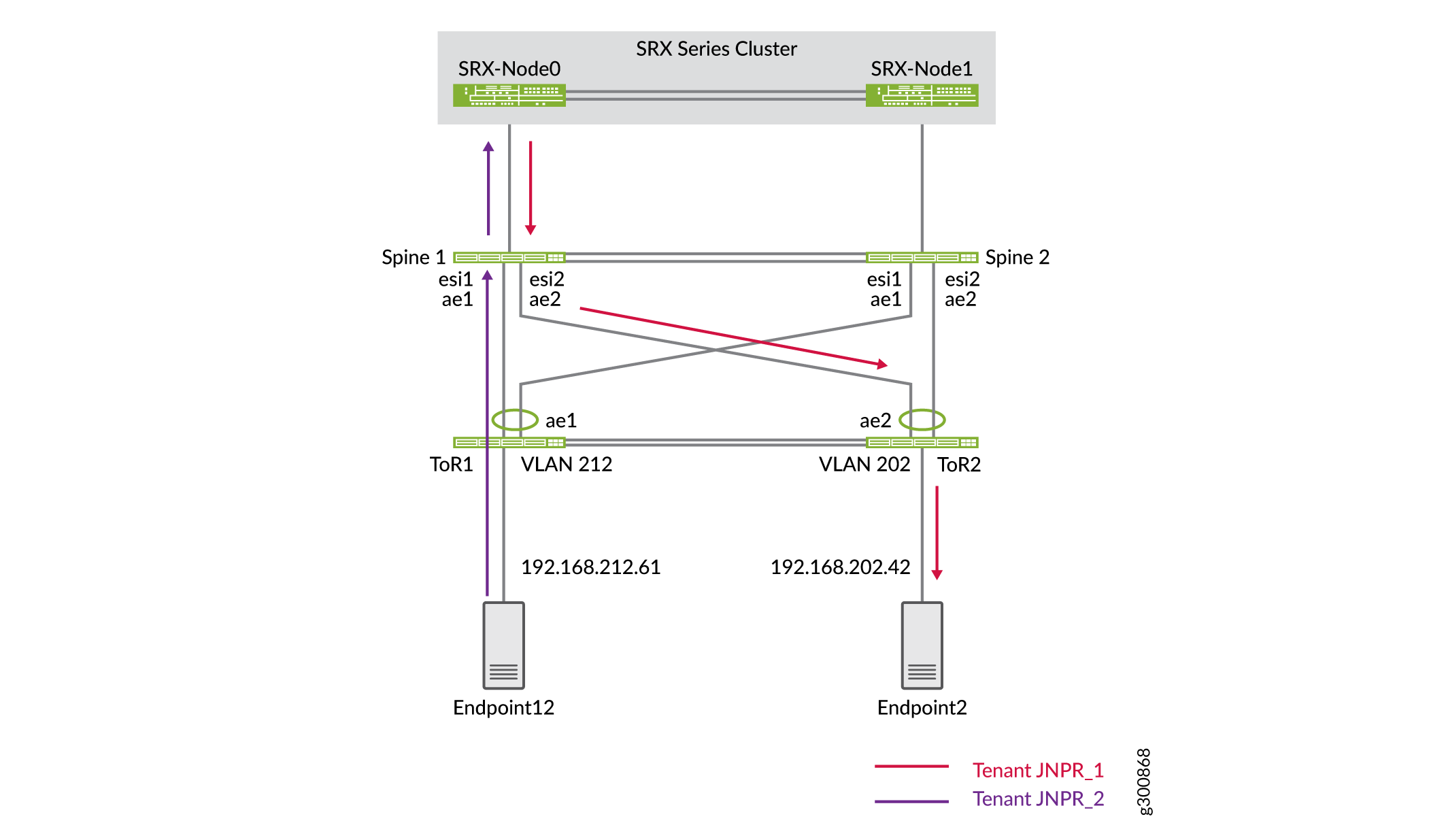 を経由するテナント間トラフィック
SRXシリーズファイアウォールのフローテーブルに、このトラフィックがSRXシャーシクラスターを通過していることが表示されていることを確認します。
user@srx> show security flow session destination-prefix 192.168.202.42
node0:
--------------------------------------------------------------------------

Session ID: 15548, Policy name: Allow_All/7, State: Active, Timeout: 2, Valid
  In: 192.168.212.61/623 --> 192.168.202.42/8204;icmp, Conn Tag: 0x0, If: reth1.992, Pkts: 1, Bytes: 84,
  Out: 192.168.202.42/8204 --> 192.168.212.61/623;icmp, Conn Tag: 0x0, If: reth1.991, Pkts: 1, Bytes: 84,

Session ID: 15551, Policy name: Allow_All/7, State: Active, Timeout: 2, Valid
  In: 192.168.212.61/624 --> 192.168.202.42/8204;icmp, Conn Tag: 0x0, If: reth1.992, Pkts: 1, Bytes: 84,
  Out: 192.168.202.42/8204 --> 192.168.212.61/624;icmp, Conn Tag: 0x0, If: reth1.991, Pkts: 1, Bytes: 84,

Session ID: 15555, Policy name: Allow_All/7, State: Active, Timeout: 4, Valid
  In: 192.168.212.61/625 --> 192.168.202.42/8204;icmp, Conn Tag: 0x0, If: reth1.992, Pkts: 1, Bytes: 84,
  Out: 192.168.202.42/8204 --> 192.168.212.61/625;icmp, Conn Tag: 0x0, If: reth1.991, Pkts: 1, Bytes: 84,
Total sessions: 3
データセンターに高度なセキュリティを設定し、テナント間トラフィックがSRXシャーシクラスターを介してルーティングされることを確認しました。
データセンターの相互接続(DCI)の設定
必要条件
概要
両方のデータセンターに集約されたスパインアーキテクチャを設定し、DC1に高度なセキュリティを追加したので、次はDCI(データセンターの相互接続)を使用してDC1とDC2を接続します。
位相幾何学
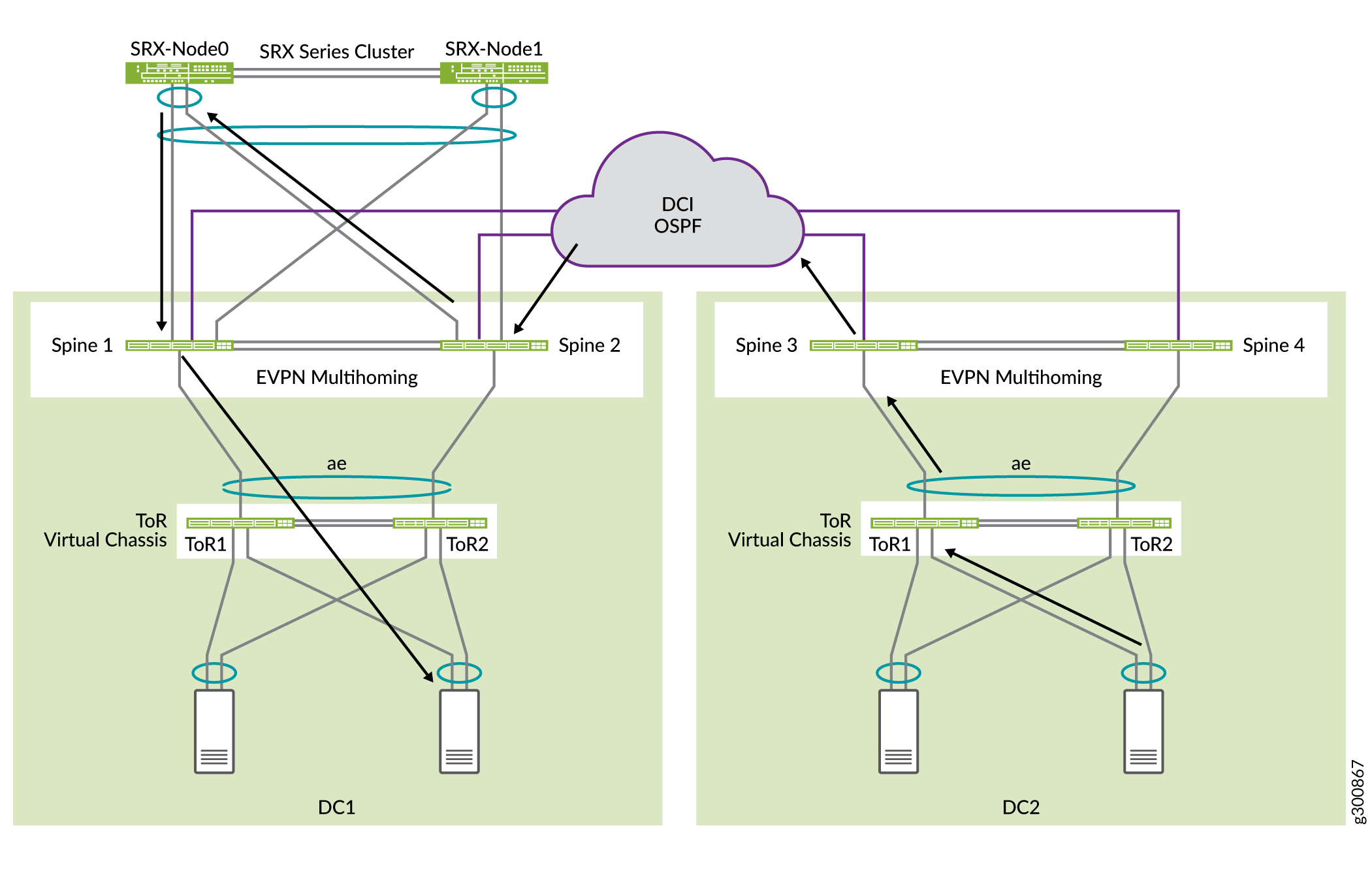
この例では、データセンター間でレイヤー2を拡張する必要はありません。データセンター間の通信は、 図5に示すように、DC1のSRXシャーシクラスターを介してルーティングされます。スパインスイッチにはそれぞれWANルーティング インスタンスがあり、データセンター間のWANに接続されています。スパインスイッチは、レイヤー3ルートをWANルーターにハンドオフします(この図には示されていません)。
SRXチャシッククラスターは、192.168.0.0/16サブネットをアドバタイズしています。DC2 スパイン スイッチのスパイン 3 とスパイン 4 は、192.168.221.0/24 および 192.168.222.0/24 の 2 つのサブネットをアドバタイズしています。
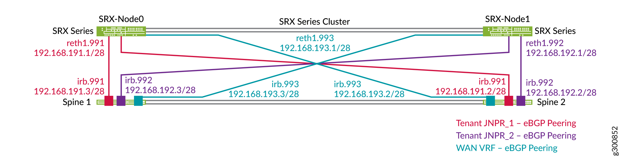
各SRXシリーズファイアウォールは、JNPR_1、JNPR_2、WANルーティングインスタンスに対応する3つのゾーンで構成されています。JNPR_1とJNPR_2間のすべてのテナント間トラフィックは、SRXシャーシクラスターを介してルーティングされます。DC1とDC2間のすべてのトラフィックは、WANルーティング インスタンスを使用してSRXシャーシ クラスターを介してルーティングされます。各SRXシリーズファイアウォールには、各ルーティングインスタンスにスパイン1およびスパイン2との個別のEBGPピアリングがあります。 図6 は、DC1のスパインスイッチとSRXシャーシクラスター間のEBGPピアリングを示しています。
構成
SRXデバイスを設定する
手順
各SRXシリーズファイアウォールは、3つのルーティングインスタンス(JNPR_1、JNPR_2、WAN)に対応する3つのゾーンに分割する必要があります。JNPR_1ゾーンとJNPR_2ゾーンは、「 テナント間トラフィックの高度なセキュリティの設定」ですでに作成済みです。
WANインターコネクト用にReth1に新しいサブインターフェイスを追加します。
set interfaces reth1 unit 993 description "DC1 Spine Interconnect for WAN VRF"
set interfaces reth1 unit 993 vlan-id 993
set interfaces reth1 unit 993 family inet address 192.168.193.1/28
WANセキュリティゾーンを設定します。
set security zones security-zone WAN-Zone host-inbound-traffic system-services ping
set security zones security-zone WAN-Zone host-inbound-traffic protocols bgp
set security zones security-zone WAN-Zone interfaces reth1.993
WANセキュリティゾーンにEBGPを設定します。
set protocols bgp group INTERCONNECT neighbor 192.168.193.2 peer-as 65312
set protocols bgp group INTERCONNECT neighbor 192.168.193.3 peer-as 65313
セキュリティポリシーを設定します。わかりやすくするために、この例のセキュリティポリシーはオープンです。設定で、必要に応じてセキュリティポリシーを変更します。
set security address-book global address 192.168.221.0/24 192.168.221.0/24
set security address-book global address 192.168.222.0/24 192.168.222.0/24
set security policies from-zone WAN-Zone to-zone JNPR_1-Zone policy ALLOW_ALL match source-address 192.168.221.0/24
set security policies from-zone WAN-Zone to-zone JNPR_1-Zone policy ALLOW_ALL match source-address 192.168.222.0/24
set security policies from-zone WAN-Zone to-zone JNPR_1-Zone policy ALLOW_ALL match destination-address any
set security policies from-zone WAN-Zone to-zone JNPR_1-Zone policy ALLOW_ALL match application any
set security policies from-zone WAN-Zone to-zone JNPR_1-Zone policy ALLOW_ALL then permit
set security policies from-zone WAN-Zone to-zone JNPR_2-Zone policy ALLOW_ALL match source-address 192.168.221.0/24
set security policies from-zone WAN-Zone to-zone JNPR_2-Zone policy ALLOW_ALL match source-address 192.168.222.0/24
set security policies from-zone WAN-Zone to-zone JNPR_2-Zone policy ALLOW_ALL match destination-address any
set security policies from-zone WAN-Zone to-zone JNPR_2-Zone policy ALLOW_ALL match application any
set security policies from-zone WAN-Zone to-zone JNPR_2-Zone policy ALLOW_ALL then permit
set security policies from-zone JNPR_1-Zone to-zone WAN-Zone policy ALLOW_ALL match source-address any
set security policies from-zone JNPR_1-Zone to-zone WAN-Zone policy ALLOW_ALL match destination-address 192.168.222.0/24
set security policies from-zone JNPR_1-Zone to-zone WAN-Zone policy ALLOW_ALL match destination-address 192.168.221.0/24
set security policies from-zone JNPR_1-Zone to-zone WAN-Zone policy ALLOW_ALL match application any
set security policies from-zone JNPR_1-Zone to-zone WAN-Zone policy ALLOW_ALL then permit
set security policies from-zone JNPR_2-Zone to-zone WAN-Zone policy ALLOW_ALL match source-address any
set security policies from-zone JNPR_2-Zone to-zone WAN-Zone policy ALLOW_ALL match destination-address 192.168.222.0/24
set security policies from-zone JNPR_2-Zone to-zone WAN-Zone policy ALLOW_ALL match destination-address 192.168.221.0/24
set security policies from-zone JNPR_2-Zone to-zone WAN-Zone policy ALLOW_ALL match application any
set security policies from-zone JNPR_2-Zone to-zone WAN-Zone policy ALLOW_ALL then permit
スパインスイッチの設定
手順
-
スパイン 1 でルーティング インスタンスと irb インターフェイスを設定します。
set interfaces irb unit 993 family inet address 192.168.193.3/28
set routing-instances WAN_VRF description "VRF for tenant WAN"
set routing-instances WAN_VRF instance-type vrf
set routing-instances WAN_VRF interface et-0/0/48.0
set routing-instances WAN_VRF interface irb.993
set routing-instances WAN_VRF interface lo0.103
set routing-instances WAN_VRF route-distinguisher 192.168.253.13:103
set routing-instances WAN_VRF vrf-target target:3:65001
set routing-instances WAN_VRF vrf-table-label
set routing-instances WAN_VRF routing-options auto-export
set routing-instances WAN_VRF routing-options multipath
set routing-instances WAN_VRF protocols bgp group INTERCONNECT type external
set routing-instances WAN_VRF protocols bgp group INTERCONNECT import Interconnect_WAN-IMPORT
set routing-instances WAN_VRF protocols bgp group INTERCONNECT family inet unicast
set routing-instances WAN_VRF protocols bgp group INTERCONNECT authentication-key "$ABC123"
set routing-instances WAN_VRF protocols bgp group INTERCONNECT export Interconnect_WAN-EXPORT
set routing-instances WAN_VRF protocols bgp group INTERCONNECT local-as 65313
set routing-instances WAN_VRF protocols bgp group INTERCONNECT multipath multiple-as
set routing-instances WAN_VRF protocols bgp group INTERCONNECT bfd-liveness-detection minimum-interval 1000
set routing-instances WAN_VRF protocols bgp group INTERCONNECT bfd-liveness-detection multiplier 3
set routing-instances WAN_VRF protocols bgp group INTERCONNECT neighbor 192.168.193.1 peer-as 65200

set routing-instances WAN_VRF protocols bgp group WAN_UNDERLAY type external
set routing-instances WAN_VRF protocols bgp group WAN_UNDERLAY description "Connection to EBGP WAN_UNDERLAY"
set routing-instances WAN_VRF protocols bgp group WAN_UNDERLAY family inet unicast
set routing-instances WAN_VRF protocols bgp group WAN_UNDERLAY authentication-key "$ABC123"
set routing-instances WAN_VRF protocols bgp group WAN_UNDERLAY local-as 65313
set routing-instances WAN_VRF protocols bgp group WAN_UNDERLAY multipath multiple-as
set routing-instances WAN_VRF protocols bgp group WAN_UNDERLAY bfd-liveness-detection minimum-interval 350
set routing-instances WAN_VRF protocols bgp group WAN_UNDERLAY bfd-liveness-detection multiplier 3
set routing-instances WAN_VRF protocols bgp group WAN_UNDERLAY neighbor 192.168.100.2 peer-as 65300
スパイン2でルーティングインスタンスを設定します。
set interfaces irb unit 993 family inet address 192.168.193.2/28
set routing-instances WAN_VRF description "VRF for tenant WAN"
set routing-instances WAN_VRF instance-type vrf
set routing-instances WAN_VRF interface et-0/0/48.0
set routing-instances WAN_VRF interface irb.993
set routing-instances WAN_VRF interface lo0.103
set routing-instances WAN_VRF route-distinguisher 192.168.253.12:103
set routing-instances WAN_VRF vrf-target target:3:65001
set routing-instances WAN_VRF vrf-table-label
set routing-instances WAN_VRF routing-options auto-export
set routing-instances WAN_VRF routing-options multipath
set routing-instances WAN_VRF protocols bgp group INTERCONNECT type external
set routing-instances WAN_VRF protocols bgp group INTERCONNECT import Interconnect_WAN-IMPORT
set routing-instances WAN_VRF protocols bgp group INTERCONNECT family inet unicast
set routing-instances WAN_VRF protocols bgp group INTERCONNECT authentication-key "$ABC123"
set routing-instances WAN_VRF protocols bgp group INTERCONNECT export Interconnect_WAN-EXPORT
set routing-instances WAN_VRF protocols bgp group INTERCONNECT local-as 65312
set routing-instances WAN_VRF protocols bgp group INTERCONNECT multipath multiple-as
set routing-instances WAN_VRF protocols bgp group INTERCONNECT bfd-liveness-detection minimum-interval 1000
set routing-instances WAN_VRF protocols bgp group INTERCONNECT bfd-liveness-detection multiplier 3
set routing-instances WAN_VRF protocols bgp group INTERCONNECT neighbor 192.168.193.1 peer-as 65200

set routing-instances WAN_VRF protocols bgp group WAN_UNDERLAY type external
set routing-instances WAN_VRF protocols bgp group WAN_UNDERLAY description "Connection to EBGP WAN_UNDERLAY"
set routing-instances WAN_VRF protocols bgp group WAN_UNDERLAY family inet unicast
set routing-instances WAN_VRF protocols bgp group WAN_UNDERLAY authentication-key "$ABC123"
set routing-instances WAN_VRF protocols bgp group WAN_UNDERLAY local-as 65312
set routing-instances WAN_VRF protocols bgp group WAN_UNDERLAY multipath multiple-as
set routing-instances WAN_VRF protocols bgp group WAN_UNDERLAY bfd-liveness-detection minimum-interval 350
set routing-instances WAN_VRF protocols bgp group WAN_UNDERLAY bfd-liveness-detection multiplier 3
set routing-instances WAN_VRF protocols bgp group WAN_UNDERLAY neighbor 192.168.100.0 peer-as 65300
スパイン3でEBGPを設定します。
set protocols bgp group WAN_UNDERLAY type external
set protocols bgp group WAN_UNDERLAY description "Connection to EBGP WAN_UNDERLAY"
set protocols bgp group WAN_UNDERLAY family inet unicast
set protocols bgp group WAN_UNDERLAY authentication-key "$ABC123"
set protocols bgp group WAN_UNDERLAY export WAN_EXPORT
set protocols bgp group WAN_UNDERLAY local-as 65322
set protocols bgp group WAN_UNDERLAY multipath multiple-as
set protocols bgp group WAN_UNDERLAY bfd-liveness-detection minimum-interval 350
set protocols bgp group WAN_UNDERLAY bfd-liveness-detection multiplier 3
set protocols bgp group WAN_UNDERLAY neighbor 192.168.100.10 peer-as 65300

set policy-options policy-statement WAN_EXPORT term DIRECT_ROUTES from protocol direct
set policy-options policy-statement WAN_EXPORT term DIRECT_ROUTES from route-filter 192.168.221.0/24 exact
set policy-options policy-statement WAN_EXPORT term DIRECT_ROUTES from route-filter 192.168.222.0/24 exact
set policy-options policy-statement WAN_EXPORT term DIRECT_ROUTES then accept
スパイン4でEBGPを設定します。
set protocols bgp group WAN_UNDERLAY type external
set protocols bgp group WAN_UNDERLAY description "Connection to EBGP WAN_UNDERLAY"
set protocols bgp group WAN_UNDERLAY family inet unicast
set protocols bgp group WAN_UNDERLAY authentication-key "$ABC123"
set protocols bgp group WAN_UNDERLAY export WAN_EXPORT
set protocols bgp group WAN_UNDERLAY local-as 65323
set protocols bgp group WAN_UNDERLAY multipath multiple-as
set protocols bgp group WAN_UNDERLAY bfd-liveness-detection minimum-interval 350
set protocols bgp group WAN_UNDERLAY bfd-liveness-detection multiplier 3
set protocols bgp group WAN_UNDERLAY neighbor 192.168.100.16 peer-as 65300

set policy-options policy-statement WAN_EXPORT term DIRECT_ROUTES from protocol direct
set policy-options policy-statement WAN_EXPORT term DIRECT_ROUTES from route-filter 192.168.221.0/24 exact
set policy-options policy-statement WAN_EXPORT term DIRECT_ROUTES from route-filter 192.168.222.0/24 exact
set policy-options policy-statement WAN_EXPORT term DIRECT_ROUTES then accept
DCI ルートの検証
手順
SRXシャーシ クラスタのルートを確認します。SRXは、異なるサブネットの特定のルートをすべて学習する必要があります。
user@srx> show route
inet.0: 31 destinations, 37 routes (31 active, 0 holddown, 0 hidden)
+ = Active Route, - = Last Active, * = Both

192.168.201.0/24   *[BGP/170] 00:59:11, localpref 100
                  	AS path: 65113 I, validation-state: unverified
                	> to 192.168.191.3 via reth1.991
192.168.201.10/32  *[BGP/170] 00:00:07, localpref 100
                  	AS path: 65113 I, validation-state: unverified
                	> to 192.168.191.3 via reth1.991
192.168.201.81/32  *[BGP/170] 00:00:07, localpref 100
                  	AS path: 65113 I, validation-state: unverified
                	> to 192.168.191.3 via reth1.991
192.168.202.0/24   *[BGP/170] 00:59:11, localpref 100
                  	AS path: 65113 I, validation-state: unverified
                	> to 192.168.191.3 via reth1.991
192.168.202.61/32  *[BGP/170] 00:59:11, localpref 100
                  	AS path: 65113 I, validation-state: unverified
                	> to 192.168.191.3 via reth1.991
192.168.202.62/32  *[BGP/170] 00:59:11, localpref 100
                  	AS path: 65113 I, validation-state: unverified
                	> to 192.168.191.3 via reth1.991
192.168.203.0/24   *[BGP/170] 00:59:11, localpref 100
                  	AS path: 65113 I, validation-state: unverified
                	> to 192.168.191.3 via reth1.991
192.168.203.61/32  *[BGP/170] 00:15:09, localpref 100
                  	AS path: 65113 I, validation-state: unverified
                	> to 192.168.191.3 via reth1.991
192.168.211.0/24   *[BGP/170] 00:34:09, localpref 100
                  	AS path: 65213 I, validation-state: unverified
                	> to 192.168.192.3 via reth1.992
192.168.212.0/24   *[BGP/170] 00:34:09, localpref 100
                  	AS path: 65213 I, validation-state: unverified
                	> to 192.168.192.3 via reth1.992
192.168.221.0/24   *[BGP/170] 00:25:07, localpref 100
                  	AS path: 65313 65300 65322 I, validation-state: unverified
                	> to 192.168.193.3 via reth1.993
192.168.222.0/24   *[BGP/170] 00:25:07, localpref 100
                  	AS path: 65313 65300 65322 I, validation-state: unverified
                	> to 192.168.193.3 via reth1.993
スパイン1とスパイン2のルートを確認します。SRXクラスターは、すべてのVRF上のスパインデバイスに192.168.0.0/16サマリールートをアドバタイズします。すべてのVRF間トラフィックとDCIトラフィックは、SRXシャーシクラスターを経由します。
user@spine1> show route 192.168.0.0
JNPR_1_VRF.inet.0: 19 destinations, 23 routes (19 active, 0 holddown, 0 hidden)
+ = Active Route, - = Last Active, * = Both

192.168.0.0/16 	*[BGP/170] 01:05:15, localpref 100
                  	AS path: 65200 I, validation-state: unverified
                	>  to 192.168.191.1 via irb.991

JNPR_2_VRF.inet.0: 13 destinations, 16 routes (13 active, 0 holddown, 0 hidden)
+ = Active Route, - = Last Active, * = Both

192.168.0.0/16 	*[BGP/170] 00:40:12, localpref 100
                  	AS path: 65200 I, validation-state: unverified
                	>  to 192.168.192.1 via irb.992

WAN_VRF.inet.0: 12 destinations, 12 routes (12 active, 0 holddown, 0 hidden)
+ = Active Route, - = Last Active, * = Both

192.168.0.0/16 	*[BGP/170] 01:04:59, localpref 100
                  	AS path: 65200 I, validation-state: unverified
                	>  to 192.168.193.1 via irb.993
スパイン3とスパイン4のルートを確認します。DC2スパインデバイスは、DC1スパインデバイス上のWAN VRFから集約ルートを受信します。2つのデータセンター間のすべてのトラフィックは、SRXシャーシクラスターを介してルーティングされます。
user@spine3> show route 192.168.0.0
inet.0: 24 destinations, 26 routes (21 active, 0 holddown, 0 hidden)
+ = Active Route, - = Last Active, * = Both

192.168.0.0/16  	[BGP ] 00:11:47
                  	AS path: 65300 65313 65200 I, validation-state: unverified
                	>  to 192.168.100.10 via et-0/0/30.0
これで、崩壊したスパインデータセンターネットワークがDCIに接続されました。