冗長な仮想トンネルを持つマルチキャストL3 VPNの耐障害性
冗長な仮想トンネルにより、マルチキャストトラフィックの配信における耐障害性の概要を実現
マルチキャストレイヤー3VPNでは、MPLSラベルに基づく仮想ルーティングおよび転送(VRF)テーブル検索を容易にするために、仮想トンネル(VT)インターフェイスが必要です。
Junos OS は、パケット転送エンジン レベルで 冗長 VT をサポートし、 マルチキャスト トラフィック配信の耐障害性を向上させます。
冗長VTは、MPCを搭載したMXシリーズルーターでのみサポートされています。
パケット転送エンジンレベルで冗長 VT を作成するには、メンバー VT(vt- インターフェイス)を親 VT(rvt インターフェイス)に追加します。
MPC を搭載した MXシリーズ ルーターで冗長 VT インターフェイスを設定するには、以下の特性があります。
冗長 VT を作成する場合、未設定の VT を冗長 VT のメンバーとして追加できます。通常の VT と同じ方法で冗長 VT を設定し、メンバー VT は親冗長 VT の設定を継承します。
既存の設定の VT が冗長 VT に参加する場合、既存の設定の設定で冗長 VT を設定する必要があります。
最大 16 個の冗長 VT を作成できます。
最大 32 個の VT を冗長 VT のメンバーとして追加できます。
手記:実際に作成できる VT の数は、シャーシのタイプとラインカードの数によって決まります。
冗長 VT に 2 つ以上の VT を追加すると、メンバーはデフォルトでアクティブ モードになり、冗長 VT を経由するトラフィックは冗長 VT のすべてのメンバー間でロード バランシングされます。
メンバーを 2 つだけ追加する場合は、次の 2 つの方法のいずれかでメンバーを設定できます。
アクティブ・モードの両方のメンバー
1 つはアクティブ モードで、もう 1 つはバックアップ モードです
ベスト プラクティス:1 つのメンバーをアクティブ モードに設定し、もう 1 つをバックアップ モードに設定するには、メンバーを異なる MPC でホストすることをお勧めします。これにより、MPC に障害が発生しても、rvt インターフェイス全体がダウンすることはありません。
VT インターフェイスを含むサービス クラスとファイアウォールの設定は、冗長 VT インターフェイスで同じように機能します。
冗長 VT は、マルチキャスト トラフィックを配信する際のネットワークに耐障害性を提供し、アップタイムを向上させるのに役立ちます。 enhanced-ip が [edit chassis network-services] 階層レベルで有効になっている場合、通常、冗長 VT のメンバーである VT の障害を検出し、50 ミリ秒以内に提供される別のメンバー VT にフェールオーバーできます。
冗長な仮想トンネルを構成してマルチキャストトラフィックの配信に耐障害性を提供する
マルチキャストレイヤー3VPNでは、MPLSラベルに基づく仮想ルーティングおよび転送(VRF)テーブル検索を容易にするために、仮想トンネル(VT)インターフェイスが必要です。
Junos OS は、パケット転送エンジン レベルで 冗長 VT をサポートし、 マルチキャスト トラフィック配信の耐障害性を向上させます。
冗長VTは、MPCを搭載したMXシリーズルーターでのみサポートされています。
パケット転送エンジン レベルで冗長 VT を作成するには、メンバー VT(vt- インターフェイス)を冗長 VT(rvt インターフェイス)に追加し、その冗長 VT インターフェイスを vrf ルーティング インスタンスに追加します。
冗長 VT を設定するには、次の手順に従います。
参照
例:冗長仮想トンネルを構成してマルチキャストトラフィック配信に耐障害性を提供する
この例では、マルチプロトコル BGP(MBGP)マルチキャスト VPN(MVPN)で冗長仮想トンネル(VT)を設定する方法を示しています。MPLSラベルに基づく仮想ルーティングおよび転送(VRF)テーブル検索を容易にするために、仮想ループバックトンネルを設定します。この方法で設定された冗長 VT は、VT の 1 つに障害が発生した場合に、ほぼ即時(50 ミリ秒未満)のフェイルオーバーを提供します。
必要条件
この例では、以下のハードウェアとソフトウェアのコンポーネントを使用しています。
-
MXシリーズルーター上のMPC
-
Junos OS リリース 15.2
概要
既存の設定の VT が冗長 VT に参加する場合、既存の設定の設定で冗長 VT を設定する必要があります。
冗長性を確保するために、メンバー VT を親 VT に追加できます。
MPC を搭載した MXシリーズ ルーターでは、以下の方法で冗長 VT を設定できます。
-
最大 16 個の冗長 VT を作成できます。
-
最大 32 個の VT を冗長 VT のメンバーとして追加できます。
手記:実際に作成できる VT の数は、シャーシのタイプとラインカードの数によって決まります。
-
冗長 VT に 2 つ以上の VT を追加すると、メンバーはデフォルトでアクティブモードになります。
-
メンバーを 2 つだけ追加する場合は、次のいずれかの方法でメンバーを設定できます。
-
アクティブ・モードの両方のメンバー
-
1 つはアクティブ モードで、もう 1 つはバックアップ モードです
-
位相幾何学
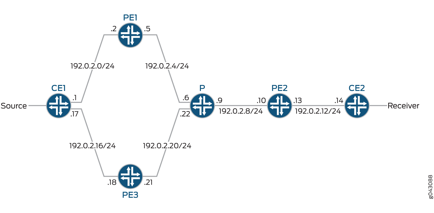
この例では、デバイス PE2 に、マルチキャスト LDP ルーティング インスタンスで設定された冗長 VT インターフェイスがあります。この例の冗長 VT インターフェイスには、アクティブ モードとバックアップ モードの 2 つのメンバー VT インターフェイスが含まれています。
図 1 は、この例で使用されているトポロジーを示しています。
 の冗長 VT インターフェイス
以下の例は、 図 1 のカスタマーエッジ(CE)、プロバイダー(P)、およびプロバイダーエッジ(PE)デバイスの設定を示しています。デバイスPE2を設定するための ステップバイステップ手順 を参照してください。
構成
1 デバイスP 1
            set chassis network-services enhanced-ip

            set interfaces ge-0/0/0 description “to PE1”

            set interfaces ge-0/0/0 unit 0 family inet address 192.0.2.6/24

            set interfaces ge-0/0/0 unit 0 family mpls

            set interfaces ge-0/0/1 description “to PE2”

            set interfaces ge-0/0/1 unit 0 family inet address 192.0.2.9/24

            set interfaces ge-0/0/1 unit 0 family mpls

            set interfaces ge-0/0/2 description “to PE3”

            set interfaces ge-0/0/2 unit 0 family inet address 192.0.2.22/24

            set interfaces ge-0/0/2 unit 0 family mpls

            set interfaces lo0 unit 0 family inet address 198.51.100.3/24

            set protocols rsvp interface all

            set protocols rsvp interface fxp0.0 disable

            set protocols mpls interface all

            set protocols mpls interface fxp0.0 disable

            set protocols bgp local-address 198.51.100.3

            set protocols bgp family inet-vpn unicast

            set protocols bgp group ibgp type internal

            set protocols bgp group ibgp local-address 198.51.100.3

            set protocols bgp group ibgp family inet any

            set protocols bgp group ibgp family inet-vpn any

            set protocols bgp group ibgp family inet-mvpn signaling

            set protocols bgp group ibgp cluster 198.51.100.3

            set protocols bgp group ibgp neighbor 198.51.100.2

            set protocols bgp group ibgp neighbor 198.51.100.4

            set protocols bgp group ibgp neighbor 198.51.100.6

            set protocols ospf traffic-engineering

            set protocols ospf area 0.0.0.0 interface lo0.0 passive

            set protocols ospf area 0.0.0.0 interface all

            set protocols ospf area 0.0.0.0 interface fxp0.0 disable

            set protocols ldp interface all

            set protocols ldp interface fxp0.0 disable

            set protocols pim interface all

            set protocols pim interface fxp0.0 disable

            set routing-options router-id 198.51.100.3

            set routing-options autonomous-system 10
デバイスPE2
            set chassis redundancy-group interface-type redundant-virtual-tunnel device-count 16

            set chassis fpc 1 pic 0 tunnel-services bandwidth 1g

            set chassis fpc 2 pic 0 tunnel-services bandwidth 1g

            set chassis network-services enhanced-ip

            set interfaces ge-0/0/0 description “to P”

            set interfaces ge-0/0/0 unit 0 family inet address 192.0.2.10/24

            set interfaces ge-0/0/0 unit 0 family mpls

            set interfaces ge-0/0/1 description “to CE2”

            set interfaces ge-0/0/1 unit 0 family inet address 192.0.2.13/24

            set interfaces ge-0/0/1 unit 0 family mpls

            set interfaces lo0 unit 0 family inet address 198.51.100.4/24

            set interfaces rvt0 redundancy-group member-interface vt-1/0/10 active

            set interfaces rvt0 redundancy-group member-interface vt-2/0/10 backup

            set interfaces rvt0 unit 1000 family inet

            set interfaces rvt0 unit 1000 family mpls

            set protocols rsvp interface ge-0/0/0.0

            set protocols rsvp interface fxp0.0 disable

            set protocols mpls label-switched-path PE2-to-PE1 to 198.51.100.2

            set protocols mpls label-switched-path PE2-to-PE3 to 198.51.100.6

            set protocols mpls interface ge-0/0/0.0

            set protocols mpls interface fxp0.0 disable

            set protocols bgp group ibgp type internal

            set protocols bgp group ibgp local-address 198.51.100.4

            set protocols bgp group ibgp family inet any

            set protocols bgp group ibgp family inet-vpn any

            set protocols bgp group ibgp family inet-mvpn signaling

            set protocols bgp group ibgp neighbor 198.51.100.3

            set protocols ospf traffic-engineering

            set protocols ospf area 0.0.0.0 interface lo0.0 passive

            set protocols ospf area 0.0.0.0 interface ge-0/0/0.0

            set protocols ospf area 0.0.0.0 interface fxp0.0 disable

            set protocols ldp interface all

            set protocols ldp interface fxp0.0 disable

            set protocols pim interface all

            set protocols pim interface fxp0.0 disable

            set policy-options policy-statement direct from protocol direct

            set policy-options policy-statement direct then accept

            set routing-instances vpn-1 instance-type vrf

            set routing-instances vpn-1 interface ge-0/0/1.0

            set routing-instances vpn-1 interface lo0.1

            set routing-instances vpn-1 interface rvt0.1000

            set routing-instances vpn-1 route-distinguisher 100:100

            set routing-instances vpn-1 vrf-target target:1:1

            set routing-instances vpn-1 routing-options multipath

            set routing-instances vpn-1 protocols bgp group CE2-PE2 type external

            set routing-instances vpn-1 protocols bgp group CE2-PE2 export direct

            set routing-instances vpn-1 protocols bgp group CE2-PE2 peer-as 100

            set routing-instances vpn-1 protocols bgp group CE2-PE2 neighbor 192.0.2.14 family inet unicast

            set routing-instances vpn-1 protocols ospf area 0.0.0.0 interface all

            set routing-instances vpn-1 protocols pim rp static address 192.168.0.0

            set routing-instances vpn-1 protocols pim interface all mode sparse

            set routing-instances vpn-1 protocols mvpn mvpn-mode spt-only

            set routing-instances vpn-1 protocols mvpn sender-based-rpf

            set routing-instances vpn-1 protocols mvpn hot-root-standby source-tree

            set routing-options router-id 198.51.100.4

            set routing-options autonomous-system 10
デバイスCE2
            set  interfaces ge-0/0/0 description “upstream to PE2”

            set  interfaces ge-0/0/0 unit 0 family inet address 192.0.2.14/24

            set  interfaces ge-0/0/0 unit 0 family mpls

            set  interfaces ge-0/0/1 description “Source-facing interface”

            set  interfaces ge-0/0/1 unit 0 family inet address 203.0.113.2/24

            set  interfaces lo0 unit 0 family inet address 198.51.100.5/24

            set  protocols bgp group CE-to-PE type external

            set  protocols bgp group CE-to-PE export direct

            set  protocols bgp group CE-to-PE peer-as 10

            set  protocols bgp group CE-to-PE local-as 100

            set  protocols bgp group CE-to-PE neighbor 192.0.2.13 family inet unicast

            set  protocols ospf area 0.0.0.0 interface lo0.0 passive

            set  protocols ospf area 0.0.0.0 interface ge-0/0/0.0

            set  protocols pim rp static address 192.168.0.0

            set  protocols pim interface all

            set  policy-options policy-statement direct from protocol direct

            set  policy-options policy-statement direct then accept

            set  routing-options router-id 198.51.100.5

            set routing-options nonstop-routing

            set routing-options autonomous-system 100
プロシージャ
手順
次の例では、設定階層のいくつかのレベルに移動する必要があります。CLIのナビゲーションについては、CLIユーザー・ガイド の コンフィギュレーション・モードでのCLIエディタの使用を参照してください。
このセクションでは、rvt インターフェイスがデバイス PE2 上に設定されます。
-
シャーシで、冗長仮想トンネル冗長グループとトンネルサービスを設定します。
[edit chassis] user@PE2# set redundancy-group interface-type redundant-virtual-tunnel device-count 16 user@PE2# set fpc 1 pic 0 tunnel-services bandwidth 1g user@PE2# set fpc 2 pic 0 tunnel-services bandwidth 1g user@PE2# set network-services enhanced-ip -
物理インターフェイスとループバックインターフェイスを設定します。
[edit interfaces] user@PE2# set ge-0/0/0 description “to P” user@PE2# set ge-0/0/0 unit 0 family inet address 192.0.2.10/24 user@PE2# set ge-0/0/0 unit 0 family mpls user@PE2# set ge-0/0/1 description “to CE2” user@PE2# set ge-0/0/1 unit 0 family inet address 192.0.2.13/24 user@PE2# set ge-0/0/1 unit 0 family mpls user@PE2# set lo0 unit 0 family inet address 198.51.100.4/24 -
rvt インターフェイスを設定します。
手記:この例では、rvt インターフェイスの 1 つのメンバーがアクティブに設定され、もう 1 つのインターフェイスがバックアップに設定されています。このアプローチでは、メンバー インターフェイスが別々の MPC 上にある必要があります。
[edit interfaces] user@PE2# set rvt0 redundancy-group member-interface vt-1/0/10 active user@PE2# set rvt0 redundancy-group member-interface vt-2/0/10 backup user@PE2# set rvt0 unit 1000 family inet user@PE2# set rvt0 unit 1000 family mpls -
MPLS を設定します。
[edit protocols mpls] user@PE2# set label-switched-path PE2-to-PE1 to 198.51.100.2 user@PE2# set label-switched-path PE2-to-PE3 to 198.51.100.6 user@PE2# set interface ge-0/0/0.0 user@PE2# set interface fxp0.0 disable -
BGP を設定します。
[edit protocols bgp] user@PE2# set group ibgp type internal user@PE2# set group ibgp local-address 198.51.100.4 user@PE2# set group ibgp family inet any user@PE2# set group ibgp family inet-vpn any user@PE2# set group ibgp family inet-mvpn signaling user@PE2# set group ibgp neighbor 198.51.100.3 -
内部ゲートウェイプロトコルを設定します。
[edit protocols ospf] user@PE2# set traffic-engineering user@PE2# set area 0.0.0.0 interface lo0.0 passive user@PE2# set area 0.0.0.0 interface ge-0/0/0.0 user@PE2# set area 0.0.0.0 interface fxp0.0 disable -
LDP、PIM、RSVP を設定します。
[edit protocols] user@PE2# set ldp interface all user@PE2# set ldp interface fxp0.0 disable user@PE2# set pim interface all user@PE2# set pim interface fxp0.0 disable user@PE2# set rsvp interface ge-0/0/0.0 user@PE2# set rsvp interface fxp0.0 disable -
ルーティングポリシーを設定します。
[edit policy-options policy-statement direct] user@PE2# set from protocol direct user@PE2# set then accept -
ルーティング インスタンスを設定します。
[edit routing-instances vpn-1] user@PE2# set instance-type vrf user@PE2# set interface ge-0/0/1.0 user@PE2# set interface lo0.1 user@PE2# set route-distinguisher 100:100 user@PE2# set vrf-target target:1:1 user@PE2# set routing-options multipath user@PE2# set protocols bgp group CE2-PE2 type external user@PE2# set protocols bgp group CE2-PE2 export direct user@PE2# set protocols bgp group CE2-PE2 peer-as 100 user@PE2# set protocols bgp group CE2-PE2 neighbor 192.0.2.14 family inet unicast user@PE2# set protocols ospf area 0.0.0.0 interface all user@PE2# set protocols pim rp static address 192.168.0.0 user@PE2# set protocols pim interface all mode sparse user@PE2# set protocols mvpn mvpn-mode spt-only user@PE2# set protocols mvpn sender-based-rpf user@PE2# set protocols mvpn hot-root-standby source-tree -
rvt インターフェイスを ルーティング インスタンス に追加します。
[edit routing-instances vpn-1] user@PE2# set interface rvt0.1000 -
ルーターIDと自律システム(AS)番号を設定します。
[edit  routing-options]
user@PE2# set router-id 198.51.100.4
user@PE2# set autonomous-system 10
業績
設定モードから、 show chassis、 show interfaces、 show protocols、 show policy-options、 show routing-instances、 show routing-options コマンドを入力して設定を確認します。出力結果に意図した設定内容が表示されない場合は、この例の設定手順を繰り返して設定を修正します。
user@PE2# show chassis
redundancy-group {
    interface-type {
        redundant-virtual-tunnel {
            device-count 16;
        }
    }
}
fpc 1 {
    pic 0 {
        tunnel-services {
            bandwidth 1g;
        }
    }
}
fpc 2 {
    pic 0 {
        tunnel-services {
            bandwidth 1g;
        }
    }
}
network-services {
    enhanced-ip;
}
user@PE2# show interfaces
ge-0/0/0 {
    description "to P";
    unit 0 {
        family inet {
            address 192.0.2.10/24;
        }
        family mpls;
    }
}
ge-0/0/1 {
    description "to CE2";
    unit 0 {
        family inet {
            address 192.0.2.13/24;
        }
        family mpls;
    }
}
lo0 {
    unit 0 {
        family inet {
            address 198.51.100.4/24;
        }
    }
}
rvt0 {
    redundancy-group {
        member-interface vt-1/0/10 {
            active;
        }
        member-interface vt-2/0/10 {
            backup;
        }
    }
    unit 1000 {
        family inet;
        family mpls;
    }
}
user@PE2# show protocols
mpls {
    label-switched-path PE2-to-PE1 {
        to 198.51.100.2;
    }
    label-switched-path PE2-to-PE3 {
        to 198.51.100.6;
    }
    interface fxp0.0 {
        disable;
    }
    interface ge-0/0/0.0;
}
bgp {
    group ibgp {
        type internal;
        local-address 198.51.100.4;
        family inet {
            any;
        }
        family inet-vpn {
            any;
        }
        family inet-mvpn {
            signaling;
        }
        neighbor 198.51.100.3;
    }
}
ospf {
    traffic-engineering;
    area 0.0.0.0 {
        interface fxp0.0 {
            disable;
        }
        interface lo0.0 {
            passive;
        }
        interface ge-0/0/0.0;
    }
}
ldp {
    interface all;
    interface fxp0.0 {
        disable;
    }
}
pim {
    interface all;
    interface fxp0.0 {
        disable;
    }
}
rsvp {
    interface fxp0.0 {
        disable;
    }
    interface ge-0/0/0.0;
}

user@PE2# show policy-options
policy-statement direct {
    from protocol direct;
    then accept;
}
user@PE2# show routing-instances
vpn-1 {
    instance-type vrf;
    interface ge-0/0/1.0;
    interface lo0.1;
    interface rvt0.1000;
    route-distinguisher 100:100;
    vrf-target target:1:1;
    routing-options {
        multipath;
    }
    protocols {
        bgp {
            group CE2-PE2 {
                type external;
                export direct;
                peer-as 100;
                neighbor 192.0.2.14 {
                    family inet {
                        unicast;
                    }
                }
            }
        }
        ospf {
            area 0.0.0.0 {
                interface all;
            }
        }
        pim {
            rp {
                static {
                    address 192.168.0.0;
                }
            }
            interface all {
                mode sparse;
            }
        }
        mvpn {
            mvpn-mode {
                spt-only;
            }
            sender-based-rpf;
            hot-root-standby {
                source-tree;
            }
        }
    }
}
user@PE2# show routing-options
router-id 198.51.100.4;
autonomous-system 10;
デバイスの設定が完了したら、設定モードから commit を入力します。
検証
設定が正常に機能していることを確認します。
- 仮想トンネルと冗長仮想トンネル インターフェイスの作成の検証
- マルチキャスト ルートへの rvt インターフェイスの組み込みの検証
- rvt インターフェイスとそのメンバー インターフェイスを介したトラフィックの検証
- バックアップ仮想トンネルへの即時フェイルオーバーの検証
仮想トンネルと冗長仮想トンネル インターフェイスの作成の検証
目的
rvt インターフェイスが作成され、適切なメンバー vt- インターフェイスが rvt インターフェイス内に含まれていることを確認します。
アクション
動作モードから、 show interfaces terse | match rvt0 コマンドを入力します。
user@PE2# show interfaces terse | match rvt0
user@host# run show interfaces terse | match rvt0
vt-1/0/10.1000          up    up   container--> rvt0.1000
vt-2/0/10.1000          up    up   container--> rvt0.1000
rvt0                    up    up
rvt0.1000               up    up   inet
意味
出力は、 rvt0 が作成され、メンバーインターフェイスとして vt-1/0/10 と vt-2/0/10 が含まれていることを示しています。
マルチキャスト ルートへの rvt インターフェイスの組み込みの検証
目的
vpn1マルチキャストルーティング インスタンスが実行されており、rvt0インターフェイスが含まれていることを確認します。
アクション
動作モードから、 show multicast route extensive instance vpn1 コマンドを入力します。
 user@PE2# show multicast route extensive instance vpn1
Instance: vpn1 Family: INET

Group: 203.0.113.3
    Source: 10.0.0.2/24
    Upstream rpf interface list:
        rvt0.1000 (P)
            Sender Id: Label 299888
    Downstream interface list:
        ge-1/0/5.0
    Number of outgoing interfaces: 1
    Session description: Unknown
    Statistics: 460 kBps, 10000 pps, 4387087 packets
    RPF Next-hop ID: 941
    Next-hop ID: 1048594
    Upstream protocol: MVPN
    Route state: Active
    Forwarding state: Forwarding
    Cache lifetime/timeout: forever
    Wrong incoming interface notifications: 0
    Uptime: 00:07:48
意味
出力は、 vpn1 ルーティング インスタンスが実行中で、 rvt0が含まれていることを示しています。
rvt インターフェイスとそのメンバー インターフェイスを介したトラフィックの検証
目的
トラフィックが rvt0 インターフェイスとそのメンバーインターフェイスを想定通りに通過することを確認します。このセクションでは、送信元から受信側へのユニキャストおよびマルチキャストトラフィックのストリームを開始します。
この例では、 rvt0 インターフェイスを通過するすべてのトラフィックがアクティブ vt-1/0/10 インターフェイスを通過することが想定されており、バックアップ vt-2/0/10 インターフェイスを通過するトラフィックはありません。
アクション
動作モードから、 monitor interface rvt0 コマンドを入力します。
 user@PE2# monitor interface rvt0
Interface: rvt0, Enabled, Link is Up
Encapsulation: VPN-Loopback-tunnel, Speed: 2000mbps
Traffic statistics:                                              Current delta
  Input bytes:                2788575982 (14720096 bps)             [10976152]
  Output bytes:                        0 (0 bps)                           [0]
  Input packets:                60621217 (40000 pps)                  [238612]
  Output packets:                      0 (0 pps)                           [0]
Error statistics:
  Input errors:                        0                                   [0]
  Input drops:                         0                                   [0]
  Input framing errors:                0                                   [0]
  Carrier transitions:                 0                                   [0]
  Output errors:                       0                                   [0]
  Output drops:                        0                                   [0]
この出力から、 rvt0 が有効でアップしており、トラフィックが流れています。
次に、 monitor interface vt-1/0/10 コマンドを入力します。
user@PE2# monitor interface vt-1/0/10
Interface: vt-1/0/10, Enabled, Link is Up
Encapsulation: VPN-Loopback-tunnel, Speed: 1000mbps
Traffic statistics:                                              Current delta
  Input bytes:                2997120202 (14720096 bps)              [3658702]
  Output bytes:                        0 (0 bps)                           [0]
  Input packets:                65154787 (40000 pps)                   [79537]
  Output packets:                      0 (0 pps)                           [0]
Error statistics:
  Input errors:                        0                                   [0]
  Input drops:                         0                                   [0]
  Input framing errors:                0                                   [0]
  Carrier transitions:                 0                                   [0]
  Output errors:                       0                                   [0]
  Output drops:                        0                                   [0]
この出力から、 rvt0 インターフェイスを通過するすべてのトラフィックは、想定どおりにアクティブな vt-1/0/10 インターフェイスを通過していることがわかります。
次に、 monitor interface vt-2/0/10 コマンドを入力します。
 user@PE2# monitor interface vt-2/0/10
Interface: vt-2/0/10, Enabled, Link is Up
Encapsulation: VPN-Loopback-tunnel, Speed: 1000mbps
Traffic statistics:                                              Current delta
  Input bytes:                         0 (0 bps)                           [0]
  Output bytes:                        0 (0 bps)                           [0]
  Input packets:                       0 (0 pps)                           [0]
  Output packets:                      0 (0 pps)                           [0]
Error statistics:
  Input errors:                        0                                   [0]
  Input drops:                         0                                   [0]
  Input framing errors:                0                                   [0]
  Carrier transitions:                 0                                   [0]
  Output errors:                       0                                   [0]
  Output drops:                        0                                   [0]
この出力から、 vt-2/0/10 が有効でアップしていても、トラフィックは通過していません。インターフェイスが backup に設定されていることから、これは正常な動作です。
意味
すべてが正常に動作している間、トラフィックは冗長仮想インターフェイスである rvt0を通過し、すべてのトラフィックはアクティブなメンバーインターフェイスを通過します。どちらのメンバーインターフェイスも active または backupに設定されていない場合、トラフィックは両方のインターフェイスでロードバランシングされることが期待されます。
バックアップ仮想トンネルへの即時フェイルオーバーの検証
目的
アクティブ メンバー インターフェイスを含む MPC に障害が発生した場合、または再起動された場合、 rvt0 インターフェイスを介したすべてのトラフィックが直ちにバックアップ メンバー インターフェイスにフェイルオーバーすることを確認します。
このタスクでは、 monitor interface vt-2/0/10 コマンドでバックアップ インターフェイスのライブ統計情報を表示するウィンドウと、アクティブ メンバー インターフェイスを含む MPC を再起動できるウィンドウを開くことをお勧めします。
アクション
運用モードから、 request chassis fpc slot 1 restart コマンドを入力し、バックアップ メンバー インターフェイスのライブ統計を観察します。
 user@PE2# request chassis fpc slot 1 restart
Interface: vt-2/0/10, Enabled, Link is Up
Encapsulation: VPN-Loopback-tunnel, Speed: 1000mbps
Traffic statistics:                                              Current delta
  Input bytes:                 354964428 (14720248 bps)             [13220676]
  Output bytes:                        0 (0 bps)                           [0]
  Input packets:                 7716618 (40000 pps)                  [287406]
  Output packets:                      0 (0 pps)                           [0]
Error statistics:
  Input errors:                        0                                   [0]
  Input drops:                         0                                   [0]
  Input framing errors:                0                                   [0]
  Carrier transitions:                 0                                   [0]
  Output errors:                       0                                   [0]
  Output drops:                        0                                   [0]
意味
この出力は、 rvt0 インターフェイスを通過したトラフィックが直ちにバックアップメンバーインターフェイスによって完全に運ばれることを示しています。
MBGP MVPNの冗長仮想トンネルインターフェイスについて
マルチプロトコルBGP(MBGP)マルチキャストVPN(MVPN)では、コアリンクでの帯域幅使用を最適化するために、組み合わせたプロバイダエッジ(PE)ルーターとプロバイダコア(P)ルーターとして機能するルーティングデバイス上のマルチキャストトラフィックにVTインターフェイスが必要です。P ルーターが PE ルーター(マルチキャスト トラフィックの出口点)としても機能する場合、VT インターフェイスはトラフィックのレプリケーションを防ぎます。
Junos OS リリース 12.3 以降では、ルーティング インスタンスで最大 8 個の VT インターフェイスを設定できるようになりました。これにより、同じマルチキャスト VPN ルーティング インスタンス内でトンネル PIC の冗長性が得られます。アクティブな VT インターフェイスに障害が発生すると、セカンダリ VT インターフェイスが引き継ぐため、重複することなくマルチキャスト トラフィックの管理を続行できます。
冗長 VT インターフェイスは、マルチキャスト LDP プロバイダー トンネルだけでなく、RSVP ポイントツーマルチポイント プロバイダー トンネルでもサポートされています。この機能は、エクストラネットでも機能します。
VT インターフェイスの 1 つをプライマリ インターフェイスとして設定できます。VT インターフェイスがプライマリとして設定されている場合、そのインターフェイスは、ラベルスイッチ パス(LSP)上のコアからルーティング インスタンスに入るトラフィックに使用されるネクスト ホップになります。VT インターフェイスがプライマリとして設定され、VT インターフェイスがユニキャスト トラフィックとマルチキャスト トラフィックの両方に使用される場合、マルチキャスト トラフィックのみが影響を受けます。
プライマリとして設定された VT インターフェイスがない場合、またはプライマリ VT インターフェイスが使用できない場合、設定された使用可能な VT インターフェイスの 1 つが、LSP のコアからルーティング インスタンスに入るトラフィックに使用されるネクスト ホップとして選択されます。使用中の VT インターフェイスが何らかの理由でダウンした場合、ルーティング インスタンスで設定されている別の使用可能な VT インターフェイスが選択されます。使用中の VT インターフェイスが変更されると、インスタンス内のすべてのマルチキャスト ルートも、トラフィックを受信できるように、リバースパス フォワーディング(RPF)インターフェイスを新しい VT インターフェイスに切り替えます。
冗長性の利点を最大限に活用するには、複数の VT インターフェイスを設定する場合、少なくとも 1 つの VT インターフェイスを他の VT インターフェイスとは異なるトンネル PIC に配置することをお勧めします。ただし、Junos OSはこれを強制しません。
例:MBGP MVPNでの冗長仮想トンネルインターフェイスの設定
この例では、マルチプロトコル BGP(MBGP)マルチキャスト VPN(MVPN)で冗長な VT(仮想トンネル)インターフェイスを設定する方法を示します。設定するには、複数の VT インターフェイスをルーティング インスタンスに含め、必要に応じて primary ステートメントを VT インターフェイスの 1 つに適用します。
必要条件
冗長 VT インターフェイスが設定されているルーティング デバイスは、Junos OS リリース 12.3 以降を搭載している必要があります。
概要
この例では、デバイス PE2 にマルチキャスト LDP ルーティング インスタンスで設定された冗長 VT インターフェイスがあり、VT インターフェイスの 1 つがプライマリ インターフェイスとして割り当てられています。
図 2 は、この例で使用されるトポロジーを示しています。
 における複数の VT インターフェイス
以下の例は、 図 2 のカスタマーエッジ(CE)、プロバイダー(P)、およびプロバイダーエッジ(PE)デバイスの設定を示しています。「 ステップバイステップの手順 」セクションでは、デバイスPE2の手順について説明します。
構成
プロシージャ
CLIクイック構成
この例をすばやく設定するには、次のコマンドをコピーしてテキストファイルに貼り付け、改行を削除して、ネットワーク構成に合わせて必要な詳細を変更し、 [edit] 階層レベルのCLIにコマンドをコピー&ペーストしてください。
デバイスCE1
set interfaces ge-1/2/0 unit 0 family inet address 10.1.1.1/30
set interfaces ge-1/2/0 unit 0 family mpls
set interfaces lo0 unit 0 family inet address 192.0.2.1/24
set protocols ospf area 0.0.0.0 interface lo0.0 passive
set protocols ospf area 0.0.0.0 interface ge-1/2/0.0
set protocols pim rp static address 198.51.100.0
set protocols pim interface all
set routing-options router-id 192.0.2.1
デバイスCE2
set  interfaces ge-1/2/0 unit 0 family inet address 10.1.1.18/30
set  interfaces ge-1/2/0 unit 0 family mpls
set  interfaces lo0 unit 0 family inet address 192.0.2.6/24
set  protocols sap listen 192.168.0.0
set  protocols ospf area 0.0.0.0 interface lo0.0 passive
set  protocols ospf area 0.0.0.0 interface ge-1/2/0.0
set  protocols pim rp static address 198.51.100.0
set  protocols pim interface all
set  routing-options router-id 192.0.2.6
デバイスCE3
set interfaces ge-1/2/0 unit 0 family inet address 10.1.1.22/30
set interfaces ge-1/2/0 unit 0 family mpls
set interfaces lo0 unit 0 family inet address 192.0.2.7/24
set protocols ospf area 0.0.0.0 interface lo0.0 passive
set protocols ospf area 0.0.0.0 interface ge-1/2/0.0
set protocols pim rp static address 198.51.100.0
set protocols pim interface all
set routing-options router-id 192.0.2.7
1 デバイスP 1
set interfaces ge-1/2/0 unit 0 family inet address 10.1.1.6/30
set interfaces ge-1/2/0 unit 0 family mpls
set interfaces ge-1/2/1 unit 0 family inet address 10.1.1.9/30
set interfaces ge-1/2/1 unit 0 family mpls
set interfaces lo0 unit 0 family inet address 192.0.2.3/24
set protocols mpls interface ge-1/2/0.0
set protocols mpls interface ge-1/2/1.0
set protocols ospf area 0.0.0.0 interface lo0.0 passive
set protocols ospf area 0.0.0.0 interface ge-1/2/0.0
set protocols ospf area 0.0.0.0 interface ge-1/2/1.0
set protocols ldp interface ge-1/2/0.0
set protocols ldp interface ge-1/2/1.0
set protocols ldp p2mp
set routing-options router-id 192.0.2.3
デバイスPE1
set interfaces ge-1/2/0 unit 0 family inet address 10.1.1.2/30
set interfaces ge-1/2/0 unit 0 family mpls
set interfaces ge-1/2/1 unit 0 family inet address 10.1.1.5/30
set interfaces ge-1/2/1 unit 0 family mpls
set interfaces vt-1/2/0 unit 2 family inet
set interfaces lo0 unit 0 family inet address 192.0.2.2/24
set interfaces lo0 unit 1 family inet address 198.51.100.0/24
set protocols mpls interface ge-1/2/1.0
set protocols bgp group ibgp type internal
set protocols bgp group ibgp local-address 192.0.2.2
set protocols bgp group ibgp family inet-vpn any
set protocols bgp group ibgp family inet-mvpn signaling
set protocols bgp group ibgp neighbor 192.0.2.4
set protocols bgp group ibgp neighbor 192.0.2.5
set protocols ospf area 0.0.0.0 interface lo0.0 passive
set protocols ospf area 0.0.0.0 interface ge-1/2/1.0
set protocols ldp interface ge-1/2/1.0
set protocols ldp p2mp
set policy-options policy-statement parent_vpn_routes from protocol bgp
set policy-options policy-statement parent_vpn_routes then accept
set routing-instances vpn-1 instance-type vrf
set routing-instances vpn-1 interface ge-1/2/0.0
set routing-instances vpn-1 interface vt-1/2/0.2 multicast
set routing-instances vpn-1 interface lo0.1
set routing-instances vpn-1 route-distinguisher 100:100
set routing-instances vpn-1 provider-tunnel ldp-p2mp
set routing-instances vpn-1 vrf-target target:1:1
set routing-instances vpn-1 protocols ospf export parent_vpn_routes
set routing-instances vpn-1 protocols ospf area 0.0.0.0 interface lo0.1 passive
set routing-instances vpn-1 protocols ospf area 0.0.0.0 interface ge-1/2/0.0
set routing-instances vpn-1 protocols pim rp static address 198.51.100.0
set routing-instances vpn-1 protocols pim interface ge-1/2/0.0 mode sparse
set routing-instances vpn-1 protocols mvpn
set routing-options router-id 192.0.2.2
set routing-options autonomous-system 1001
デバイスPE2
set interfaces ge-1/2/0 unit 0 family inet address 10.1.1.10/30
set interfaces ge-1/2/0 unit 0 family mpls
set interfaces ge-1/2/2 unit 0 family inet address 10.1.1.13/30
set interfaces ge-1/2/2 unit 0 family mpls
set interfaces ge-1/2/1 unit 0 family inet address 10.1.1.17/30
set interfaces ge-1/2/1 unit 0 family mpls
set interfaces vt-1/1/0 unit 0 family inet
set interfaces vt-1/2/1 unit 0 family inet
set interfaces lo0 unit 0 family inet address 192.0.2.4/24
set interfaces lo0 unit 1 family inet address 203.0.113.4/24
set protocols mpls interface ge-1/2/0.0
set protocols mpls interface ge-1/2/2.0
set protocols bgp group ibgp type internal
set protocols bgp group ibgp local-address 192.0.2.4
set protocols bgp group ibgp family inet-vpn any
set protocols bgp group ibgp family inet-mvpn signaling
set protocols bgp group ibgp neighbor 192.0.2.2
set protocols bgp group ibgp neighbor 192.0.2.5
set protocols ospf area 0.0.0.0 interface lo0.0 passive
set protocols ospf area 0.0.0.0 interface ge-1/2/0.0
set protocols ospf area 0.0.0.0 interface ge-1/2/2.0
set protocols ldp interface ge-1/2/0.0
set protocols ldp interface ge-1/2/2.0
set protocols ldp p2mp
set policy-options policy-statement parent_vpn_routes from protocol bgp
set policy-options policy-statement parent_vpn_routes then accept
set routing-instances vpn-1 instance-type vrf
set routing-instances vpn-1 interface vt-1/1/0.0 multicast
set routing-instances vpn-1 interface vt-1/1/0.0 primary
set routing-instances vpn-1 interface vt-1/2/1.0 multicast
set routing-instances vpn-1 interface ge-1/2/1.0
set routing-instances vpn-1 interface lo0.1
set routing-instances vpn-1 route-distinguisher 100:100
set routing-instances vpn-1 vrf-target target:1:1
set routing-instances vpn-1 protocols ospf export parent_vpn_routes
set routing-instances vpn-1 protocols ospf area 0.0.0.0 interface lo0.1 passive
set routing-instances vpn-1 protocols ospf area 0.0.0.0 interface ge-1/2/1.0
set routing-instances vpn-1 protocols pim rp static address 198.51.100.0
set routing-instances vpn-1 protocols pim interface ge-1/2/1.0 mode sparse
set routing-instances vpn-1 protocols mvpn
set routing-options router-id 192.0.2.4
set routing-options autonomous-system 1001
デバイスPE3
set interfaces ge-1/2/0 unit 0 family inet address 10.1.1.14/30
set interfaces ge-1/2/0 unit 0 family mpls
set interfaces ge-1/2/1 unit 0 family inet address 10.1.1.21/30
set interfaces ge-1/2/1 unit 0 family mpls
set interfaces vt-1/2/0 unit 5 family inet
set interfaces lo0 unit 0 family inet address 192.0.2.5/24
set interfaces lo0 unit 1 family inet address 203.0.113.5/24
set protocols mpls interface ge-1/2/0.0
set protocols bgp group ibgp type internal
set protocols bgp group ibgp local-address 192.0.2.5
set protocols bgp group ibgp family inet-vpn any
set protocols bgp group ibgp family inet-mvpn signaling
set protocols bgp group ibgp neighbor 192.0.2.2
set protocols bgp group ibgp neighbor 192.0.2.4
set protocols ospf area 0.0.0.0 interface lo0.0 passive
set protocols ospf area 0.0.0.0 interface ge-1/2/0.0
set protocols ldp interface ge-1/2/0.0
set protocols ldp p2mp
set policy-options policy-statement parent_vpn_routes from protocol bgp
set policy-options policy-statement parent_vpn_routes then accept
set routing-instances vpn-1 instance-type vrf
set routing-instances vpn-1 interface vt-1/2/0.5 multicast
set routing-instances vpn-1 interface ge-1/2/1.0
set routing-instances vpn-1 interface lo0.1
set routing-instances vpn-1 route-distinguisher 100:100
set routing-instances vpn-1 vrf-target target:1:1
set routing-instances vpn-1 protocols ospf export parent_vpn_routes
set routing-instances vpn-1 protocols ospf area 0.0.0.0 interface lo0.1 passive
set routing-instances vpn-1 protocols ospf area 0.0.0.0 interface ge-1/2/1.0
set routing-instances vpn-1 protocols pim rp static address 198.51.100.0
set routing-instances vpn-1 protocols pim interface ge-1/2/1.0 mode sparse
set routing-instances vpn-1 protocols mvpn
set routing-options router-id 192.0.2.5
set routing-options autonomous-system 1001
手順
次の例では、設定階層のいくつかのレベルに移動する必要があります。CLIのナビゲーションについては、CLIユーザー・ガイド の コンフィギュレーション・モードでのCLIエディタの使用を参照してください。
MBGP MVPN で冗長 VT インターフェイスを設定するには:
物理インターフェイスとループバックインターフェイスを設定します。
[edit interfaces]
user@PE2# set ge-1/2/0 unit 0 family inet address 10.1.1.10/30
user@PE2# set ge-1/2/0 unit 0 family mpls
user@PE2# set ge-1/2/2 unit 0 family inet address 10.1.1.13/30
user@PE2# set ge-1/2/2 unit 0 family mpls
user@PE2# set ge-1/2/1 unit 0 family inet address 10.1.1.17/30
user@PE2# set ge-1/2/1 unit 0 family mpls
user@PE2# set lo0 unit 0 family inet address 192.0.2.4/24
user@PE2# set lo0 unit 1 family inet address 203.0.113.4/24
VT インターフェイスを設定します。
各 VT インターフェイスは、1 つのルーティング インスタンスで設定できます。
[edit interfaces]
user@PE2# set vt-1/1/0 unit 0 family inet
user@PE2# set vt-1/2/1 unit 0 family inet
物理インターフェイスに MPLS を設定します。
[edit  protocols mpls]
user@PE2# set interface ge-1/2/0.0
user@PE2# set interface ge-1/2/2.0
BGP を設定します。
[edit  protocols bgp group ibgp]
user@PE2# set type internal
user@PE2# set local-address 192.0.2.4
user@PE2# set family inet-vpn any
user@PE2# set family inet-mvpn signaling
user@PE2# set neighbor 192.0.2.2
user@PE2# set neighbor 192.0.2.5
内部ゲートウェイプロトコルを設定します。
[edit  protocols ospf area 0.0.0.0]
user@PE2# set interface lo0.0 passive
user@PE2# set interface ge-1/2/0.0
user@PE2# set interface ge-1/2/2.0
LDP を設定します。
[edit  protocols ldp]
user@PE2# set interface ge-1/2/0.0
user@PE2# set interface ge-1/2/2.0
user@PE2# set p2mp
ルーティングポリシーを設定します。
[edit  policy-options policy-statement parent_vpn_routes]
user@PE2# set from protocol bgp
user@PE2# set then accept
ルーティング インスタンスを設定します。
[edit  routing-instances vpn-1]
user@PE2# set instance-type vrf
user@PE2# set interface ge-1/2/1.0
user@PE2# set interface lo0.1
user@PE2# set route-distinguisher 100:100
user@PE2# set vrf-target target:1:1
user@PE2# set protocols ospf export parent_vpn_routes
user@PE2# set protocols ospf area 0.0.0.0 interface lo0.1 passive
user@PE2# set protocols ospf area 0.0.0.0 interface ge-1/2/1.0
user@PE2# set protocols pim rp static address 198.51.100.0
user@PE2# set protocols pim interface ge-1/2/1.0 mode sparse
user@PE2# set protocols mvpn
ルーティング インスタンスで冗長 VT インターフェイスを設定します。
vt-1/1/0.0 をプライマリ インターフェイスにします。
[edit  routing-instances vpn-1]
user@PE2# set interface vt-1/1/0.0 multicast primary
user@PE2# set interface vt-1/2/1.0 multicast
ルーターIDと自律システム(AS)番号を設定します。
[edit  routing-options]
user@PE2# set router-id 192.0.2.4
user@PE2# set autonomous-system 1001
業績
設定モードから、 show interfaces、 show protocols、 show policy-options、 show routing-instances、 show routing-options コマンドを入力して設定を確認します。出力結果に意図した設定内容が表示されない場合は、この例の設定手順を繰り返して設定を修正します。
user@PE2# show interfaces
ge-1/2/0 {
    unit 0 {
        family inet {
            address 10.1.1.10/30;
        }
        family mpls;
    }
}
ge-1/2/2 {
    unit 0 {
        family inet {
            address 10.1.1.13/30;
        }
        family mpls;
    }
}
ge-1/2/1 {
    unit 0 {
        family inet {
            address 10.1.1.17/30;
        }
        family mpls;
    }
}
vt-1/1/0 {
    unit 0 {
        family inet;
    }
}
vt-1/2/1 {
    unit 0 {
        family inet;
    }
}
lo0 {
    unit 0 {
        family inet {
            address 192.0.2.4/24;
        }
    }
    unit 1 {
        family inet {
            address 203.0.113.4/24;
        }
    }
}
user@PE2# show protocols
mpls {
    interface ge-1/2/0.0;
    interface ge-1/2/2.0;
}
bgp {
    group ibgp {
        type internal;
        local-address 192.0.2.4;
        family inet-vpn {
            any;
        }
        family inet-mvpn {
            signaling;
        }
        neighbor 192.0.2.2;
        neighbor 192.0.2.5;
    }
}
ospf {
    area 0.0.0.0 {
        interface lo0.0 {
            passive;
        }
        interface ge-1/2/0.0;
        interface ge-1/2/2.0;
    }
}
ldp {
    interface ge-1/2/0.0;
    interface ge-1/2/2.0;
    p2mp;
}
user@PE2# show policy-options
policy-statement parent_vpn_routes {
    from protocol bgp;
    then accept;
}
user@PE2# show routing-instances
vpn-1 {
    instance-type vrf;
    interface vt-1/1/0.0 {
        multicast;
        primary;
    }
    interface vt-1/2/1.0 {
        multicast;
    }
    interface ge-1/2/1.0;
    interface lo0.1;
    route-distinguisher 100:100;
    vrf-target target:1:1;
    protocols {
        ospf {
            export parent_vpn_routes;
            area 0.0.0.0 {
                interface lo0.1 {
                    passive;
                }
                interface ge-1/2/1.0;
            }
        }
        pim {
            rp {
                static {
                    address 198.51.100.0;
                }
            }
            interface ge-1/2/1.0 {
                mode sparse;
            }
        }
        mvpn;
    }
}
user@PE2# show routing-options
router-id 192.0.2.4;
autonomous-system 1001;
デバイスの設定が完了したら、設定モードから commit を入力します。
検証
設定が正常に機能していることを確認します。
show multicast route extensive instance instance-name コマンドは、マルチキャスト トラフィックが VPN 経由で送信されるときに、マルチキャスト 転送テーブルの VT インターフェイスも表示します。
LSPルートの確認
目的
予想されるLTインターフェイスがLDP学習ルートに割り当てられていることを確認します。
アクション
動作モードから、 show route table mpls コマンドを入力します。
user@PE2> show route table mpls
mpls.0: 13 destinations, 13 routes (13 active, 0 holddown, 0 hidden)
+ = Active Route, - = Last Active, * = Both

0                  *[MPLS/0] 02:09:36, metric 1
                         Receive
1                  *[MPLS/0] 02:09:36, metric 1
                         Receive
2                  *[MPLS/0] 02:09:36, metric 1
                         Receive
13                 *[MPLS/0] 02:09:36, metric 1
                         Receive
299776             *[LDP/9] 02:09:14, metric 1
                    >    via ge-1/2/0.0, Pop
299776(S=0)        *[LDP/9] 02:09:14, metric 1
                    >    via ge-1/2/0.0, Pop
299792             *[LDP/9] 02:09:09, metric 1
                    >    via ge-1/2/2.0, Pop
299792(S=0)        *[LDP/9] 02:09:09, metric 1
                    >    via ge-1/2/2.0, Pop
299808             *[LDP/9] 02:09:04, metric 1
                    >    via ge-1/2/0.0, Swap 299808
299824             *[VPN/170] 02:08:56
                    >    via ge-1/2/1.0, Pop
299840             *[VPN/170] 02:08:56
                    >    via ge-1/2/1.0, Pop
299856             *[VPN/170] 02:08:56
                      receive table vpn-1.inet.0, Pop
299872             *[LDP/9] 02:08:54, metric 1
                    >    via vt-1/1/0.0, Pop
                         via ge-1/2/2.0, Swap 299872
設定モードから、vt-1/1/0.0 インターフェイスから
primaryステートメントを削除し、vt-1/2/1.0 インターフェイスに追加して、プライマリ VT インターフェイスを変更します。[edit routing-instances vpn-1] user@PE2# delete interface vt-1/1/0.0 primary user@PE2# set interface vt-1/2/1.0 primary user@PE2# commit
動作モードから、 show route table mpls コマンドを入力します。
user@PE2> show route table mpls
mpls.0: 13 destinations, 13 routes (13 active, 0 holddown, 0 hidden)
+ = Active Route, - = Last Active, * = Both

0                  *[MPLS/0] 02:09:36, metric 1
                         Receive
1                  *[MPLS/0] 02:09:36, metric 1
                         Receive
2                  *[MPLS/0] 02:09:36, metric 1
                         Receive
13                 *[MPLS/0] 02:09:36, metric 1
                         Receive
299776             *[LDP/9] 02:09:14, metric 1
                    >    via ge-1/2/0.0, Pop
299776(S=0)        *[LDP/9] 02:09:14, metric 1
                    >    via ge-1/2/0.0, Pop
299792             *[LDP/9] 02:09:09, metric 1
                    >    via ge-1/2/2.0, Pop
299792(S=0)        *[LDP/9] 02:09:09, metric 1
                    >    via ge-1/2/2.0, Pop
299808             *[LDP/9] 02:09:04, metric 1
                    >    via ge-1/2/0.0, Swap 299808
299824             *[VPN/170] 02:08:56
                    >    via ge-1/2/1.0, Pop
299840             *[VPN/170] 02:08:56
                    >    via ge-1/2/1.0, Pop
299856             *[VPN/170] 02:08:56
                      receive table vpn-1.inet.0, Pop
299872             *[LDP/9] 02:08:54, metric 1
                    >    via vt-1/2/1.0, Pop
                         via ge-1/2/2.0, Swap 299872
意味
元の設定では、出力は vt-1/1/0.0 インターフェイスを示しています。プライマリインターフェイスをvt-1/2/1.0に変更すると、出力はvt-1/2/1.0インターフェイスを表示します。
変更履歴
サポートされる機能は、使用しているプラットフォームとリリースによって決まります。特定の機能がお使いのプラットフォームでサポートされているかどうかを確認するには、 Feature Explorer を使用します。