OSPFv2 シャム リンクの設定
OSPFv2 シャム リンクの概要
2 つのプロバイダー エッジ(PE)ルーティング デバイス間にエリア内リンクまたはシャム リンクを作成して、VPN バックボーンがバックドア リンクよりも優先されるようにすることができます。バックドアリンクは、VPNバックボーンが利用できない場合に、カスタマーエッジ(CE)デバイスを接続するバックアップリンクです。このようなバックアップ リンクが利用可能で、CE デバイスが同じ OSPF エリアにある場合、デフォルトの動作では、VPN バックボーンよりもこのバックアップ リンクが優先されます。これは、バックアップ リンクは常にエリア内リンクと見なされ、VPN バックボーンは常にエリア間リンクと見なされるためです。エリア内リンクは、常にエリア間リンクよりも優先されます。
シャム リンクは、PE デバイス間の番号のないポイントツーポイントのエリア内リンクです。VPN バックボーンにシャムエリア内リンクがある場合、シャム リンクの OSPF メトリックがバックアップ リンクよりも低い場合は、このシャム リンクをバックアップ リンクよりも優先できます。
模造リンクは、タイプ1のリンク状態アドバタイズ(LSA)を使用してアドバタイズされます。シャム リンクは、ルーティング インスタンスと OSPFv2 に対してのみ有効です。
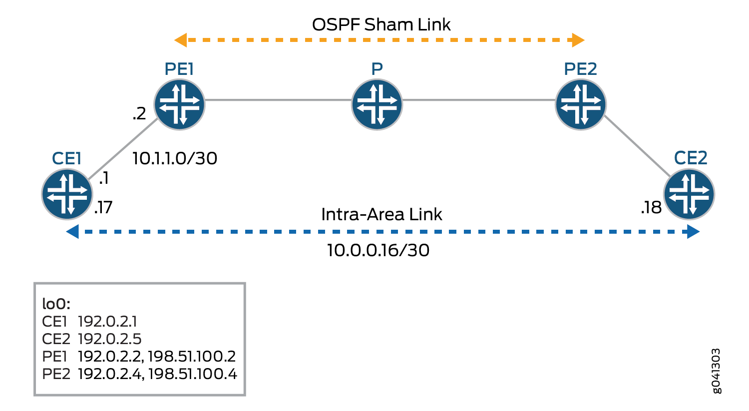
各模造リンクは、ローカルエンドポイントアドレスとリモートエンドポイントアドレスの組み合わせで識別されます。 図 1 に OSPFv2 シャム リンクを示します。ルーターCE1とルーターCE2は、同じOSPFv2エリアにあります。これらのカスタマーエッジ(CE)ルーティングデバイスは、ルーターPE1とルーターPE2を介したレイヤー3 VPNによってリンクされています。また、ルーターCE1とルーターCE2は、バックアップとして使用されるエリア内リンクで接続されています。
OSPFv2 は、レイヤー 3 VPN を介したリンクをエリア間リンクとして扱います。デフォルトでは、OSPFv2 はエリア間リンクよりもエリア内リンクを優先するため、OSPFv2 はバックアップのエリア内リンクをアクティブ パスとして選択します。これは、エリア内リンクがCEルーティングデバイス間のトラフィックの予期されるプライマリパスではない設定では許容されません。シャムリンクのメトリックを設定して、レイヤー3 VPN上のパスが、CEルーティングデバイスを接続するエリア内リンク上のバックアップパスよりも優先されるようにすることができます。
リモート エンドポイントでは、OSPFv2 インターフェイスをデマンド回線として設定し、IPsec 認証を設定し(実際の IPsec 認証は別途設定)、メトリック値を定義できます。
OSPFv2 シャム リンクは、以下の状況で設定する必要があります。
2 つの CE ルーティング デバイスは、レイヤー 3 VPN によってリンクされています。
これらの CE ルーティング デバイスは、同じ OSPFv2 エリア内にあります。
2台のCEルーティングデバイス間には、エリア内リンクが設定されています。
CE ルーティング デバイス間にエリア内リンクがない場合は、OSPFv2 シャム リンクを設定する必要はありません。
Junos OS リリース 9.6 以降では、OSPFv2 模造リンクは非表示ルートとしてルーティングテーブルにインストールされます。また、対応する OSPF シャム リンクが利用可能な場合、BGP ルートは OSPFv2 にエクスポートされません。
Junos OS リリース 16.1 以降では、OSPF 模造リンクがデフォルト インスタンスでサポートされています。模造リンクのコストは、ユーザーが模造リンクにメトリックを設定しない場合、BGP ルートの aigp-metric に動的に設定されます。BGP ルートに aigp-metric が存在しない場合、模造リンク コストはデフォルトで 1 になります。
例:OSPFv2 シャム リンクの設定
この例では、PE ルーティング デバイスで OSPFv2 シャム リンクを有効にする方法を示しています。
必要条件
この例を設定する前に、デバイス初期化以外の特別な設定を行う必要はありません。
概要
シャムリンクは、番号なしのポイントツーポイントエリア内リンクであり、タイプ1のリンク状態アドバタイズメント(LSA)によってアドバタイズされます。シャム リンクは、ルーティング インスタンスと OSPFv2 に対してのみ有効です。
各模造リンクは、ローカル エンドポイント アドレスとリモート エンドポイント アドレス、およびそれが属する OSPFv2 エリアの組み合わせによって識別されます。同じ VPN ルーティングおよび転送(VRF)ルーティング インスタンス内にある 2 つの PE デバイス間のシャム リンクを手動で設定し、シャム リンクのローカル エンドポイントのアドレスを指定します。このアドレスは、模造リンク パケットの送信元として使用され、リモート PE ルーティング デバイスによって模造リンクのリモート エンドポイントとしても使用されます。また、オプションの metric オプションを含めて、リモートエンドポイントのメトリック値を設定することもできます。メトリック値は、リンクの使用コストを指定します。総パスメトリック値が低いルートが、パスメトリック値が高いルートよりも優先されます。
PE ルーティング デバイスで OSPFv2 シャム リンクを有効にするには:
PEルーティングデバイスに追加のループバックインターフェイスを設定します。
PE ルーティング デバイスでレイヤー 3 VPN をサポートする VRF ルーティング インスタンスを設定し、模造リンクを既存の OSPF エリアに関連付けます。OSPFv2 模造リンク設定も、ルーティング インスタンスに含まれます。模造リンクのローカルエンドポイントアドレス(ローカルVPNのループバックアドレス)とリモートエンドポイントアドレス(リモートVPNのループバックアドレス)を設定します。この例では、VRF ルーティング インスタンスの名前は red です。
図 2 に OSPFv2 シャム リンクを示します。
位相幾何学
図のデバイスは、次の機能を表しています。
CE1とCE2はカスタマーエッジデバイスです。
PE1 と PE2 はプロバイダー エッジ デバイスです。
P はプロバイダー デバイスです。
CLIクイック構成 は、 図 2 のすべてのデバイスの設定を示しています。「 ステップバイステップの手順 」セクションでは、デバイスPE1の手順を説明します。
構成
プロシージャ
CLIクイック構成
この例をすばやく設定するには、次のコマンドをコピーしてテキストファイルに貼り付け、改行を削除して、ネットワーク構成に合わせて必要な詳細を変更し、 [edit] 階層レベルのCLIにコマンドをコピー&ペーストしてください。
CE1の
set interfaces fe-1/2/0 unit 0 family inet address 10.1.1.1/30
set interfaces fe-1/2/0 unit 0 family mpls
set interfaces fe-1/2/1 unit 0 family inet address 10.0.0.17/30
set interfaces lo0 unit 0 family inet address 192.0.2.1/24
set protocols ospf area 0.0.0.0 interface fe-1/2/0.0
set protocols ospf area 0.0.0.0 interface lo0.0 passive
set protocols ospf area 0.0.0.0 interface fe-1/2/1.0 metric 100
set policy-options policy-statement send-direct from protocol direct
set policy-options policy-statement send-direct then accept
set routing-options router-id 192.0.2.1
set routing-options autonomous-system 1
PE1
set interfaces fe-1/2/0 unit 0 family inet address 10.1.1.2/30
set interfaces fe-1/2/0 unit 0 family mpls
set interfaces fe-1/2/1 unit 0 family inet address 10.1.1.5/30
set interfaces fe-1/2/1 unit 0 family mpls
set interfaces lo0 unit 0 family inet address 192.0.2.2/24
set interfaces lo0 unit 1 family inet address 198.51.100.2/24
set protocols mpls interface fe-1/2/1.0
set protocols bgp group toR4 type internal
set protocols bgp group toR4 local-address 192.0.2.2
set protocols bgp group toR4 family inet-vpn unicast
set protocols bgp group toR4 neighbor 192.0.2.4
set protocols ospf area 0.0.0.0 interface fe-1/2/1.0
set protocols ospf area 0.0.0.0 interface lo0.0 passive
set protocols ldp interface fe-1/2/1.0
set protocols ldp interface lo0.0
set policy-options policy-statement bgp-to-ospf term 1 from protocol bgp
set policy-options policy-statement bgp-to-ospf term 1 then accept
set policy-options policy-statement bgp-to-ospf term 2 then reject
set routing-instances red instance-type vrf
set routing-instances red interface fe-1/2/0.0
set routing-instances red interface lo0.1
set routing-instances red route-distinguisher 2:1
set routing-instances red vrf-target target:2:1
set routing-instances red protocols ospf export bgp-to-ospf
set routing-instances red protocols ospf sham-link local 198.51.100.2
set routing-instances red protocols ospf area 0.0.0.0 sham-link-remote 198.51.100.4 metric 10
set routing-instances red protocols ospf area 0.0.0.0 interface fe-1/2/0.0
set routing-instances red protocols ospf area 0.0.0.0 interface lo0.1
set routing-options router-id 192.0.2.2
set routing-options autonomous-system 2
P
set interfaces fe-1/2/0 unit 0 family inet address 10.1.1.6/30
set interfaces fe-1/2/0 unit 0 family mpls
set interfaces fe-1/2/1 unit 0 family inet address 10.1.1.9/30
set interfaces fe-1/2/1 unit 0 family mpls
set interfaces lo0 unit 3 family inet address 192.0.2.3/24
set protocols mpls interface all
set protocols ospf area 0.0.0.0 interface lo0.3 passive
set protocols ospf area 0.0.0.0 interface all
set protocols ldp interface all
set routing-options router-id 192.0.2.3
PE2の
set interfaces fe-1/2/0 unit 0 family inet address 10.1.1.10/30
set interfaces fe-1/2/0 unit 0 family mpls
set interfaces fe-1/2/1 unit 0 family inet address 10.1.1.13/30
set interfaces fe-1/2/1 unit 0 family mpls
set interfaces lo0 unit 0 family inet address 192.0.2.4/32
set interfaces lo0 unit 1 family inet address 198.51.100.4/32
set protocols mpls interface fe-1/2/0.0
set protocols bgp group toR2 type internal
set protocols bgp group toR2 local-address 192.0.2.4
set protocols bgp group toR2 family inet-vpn unicast
set protocols bgp group toR2 neighbor 192.0.2.2
set protocols ospf area 0.0.0.0 interface lo0.0 passive
set protocols ospf area 0.0.0.0 interface fe-1/2/0.0
set protocols ldp interface fe-1/2/0.0
set protocols ldp interface lo0.0
set policy-options policy-statement bgp-to-ospf term 1 from protocol bgp
set policy-options policy-statement bgp-to-ospf term 1 then accept
set policy-options policy-statement bgp-to-ospf term 2 then reject
set routing-instances red instance-type vrf
set routing-instances red interface fe-1/2/1.0
set routing-instances red interface lo0.1
set routing-instances red route-distinguisher 2:1
set routing-instances red vrf-target target:2:1
set routing-instances red protocols ospf export bgp-to-ospf
set routing-instances red protocols ospf sham-link local 198.51.100.4
set routing-instances red protocols ospf area 0.0.0.0 sham-link-remote 198.51.100.2 metric 10
set routing-instances red protocols ospf area 0.0.0.0 interface fe-1/2/1.0
set routing-instances red protocols ospf area 0.0.0.0 interface lo0.1
set routing-options router-id 192.0.2.4
set routing-options autonomous-system 2
CE2の
set interfaces fe-1/2/0 unit 14 family inet address 10.1.1.14/30
set interfaces fe-1/2/0 unit 14 family mpls
set interfaces fe-1/2/0 unit 18 family inet address 10.0.0.18/30
set interfaces lo0 unit 5 family inet address 192.0.2.5/24
set protocols ospf area 0.0.0.0 interface fe-1/2/0.14
set protocols ospf area 0.0.0.0 interface lo0.5 passive
set protocols ospf area 0.0.0.0 interface fe-1/2/0.18
set policy-options policy-statement send-direct from protocol direct
set policy-options policy-statement send-direct then accept
set routing-options router-id 192.0.2.5
set routing-options autonomous-system 3
手順
次の例では、設定階層のいくつかのレベルに移動する必要があります。CLIのナビゲーションについては、CLIユーザーガイドの Junos OS設定の変更を参照してください。
各 PE デバイスで OSPFv2 シャム リンクを設定するには:
-
2つのループバックインターフェイスを含むインターフェイスを設定します。
[edit interfaces]
user@PE1# set fe-1/2/0 unit 0 family inet address 10.1.1.2/30
user@PE1# set fe-1/2/0 unit 0 family mpls
user@PE1# set fe-1/2/1 unit 0 family inet address 10.1.1.5/30
user@PE1# set fe-1/2/1 unit 0 family mpls
user@PE1# set lo0 unit 0 family inet address 192.0.2.2/24
user@PE1# set lo0 unit 1 family inet address 198.51.100.2/24
-
コアに面するインターフェイスでMPLSを設定します。
[edit protocols mpls]
user@PE1# set interface fe-1/2/1.0
-
内部BGP(IBGP)を設定します。
[edit ]
user@PE1# set protocols bgp group toR4 type internal
user@PE1# set protocols bgp group toR4 local-address 192.0.2.2
user@PE1# set protocols bgp group toR4 family inet-vpn unicast
user@PE1# set protocols bgp group toR4 neighbor 192.0.2.4
-
コアに面したインターフェイスと、メインインスタンスで使用されているループバックインターフェイスでOSPFを設定します。
[edit protocols ospf area 0.0.0.0]
user@PE1# set interface fe-1/2/1.0
user@PE1# set interface lo0.0 passive
-
コアに面したインターフェイスとメインインスタンスで使用されているループバックインターフェイスでLDPまたはRSVPを設定します。
[edit protocols ldp]
user@PE1# set interface fe-1/2/1.0
user@PE1# set interface lo0.0
-
ルーティング インスタンスで使用するルーティングポリシーを設定します。
[edit policy-options policy-statement bgp-to-ospf]
user@PE1# set term 1 from protocol bgp
user@PE1# set term 1 then accept
user@PE1# set term 2 then reject
-
ルーティング インスタンスを設定します。
[edit routing-instances red]
user@PE1# set instance-type vrf
user@PE1# set interface fe-1/2/0.0
user@PE1# set route-distinguisher 2:1
user@PE1# set vrf-target target:2:1
user@PE1# set protocols ospf export bgp-to-ospf
user@PE1# set protocols ospf area 0.0.0.0 interface fe-1/2/0.0
-
OSPFv2 シャム リンクを設定します。
追加のループバック インターフェイスを、ルーティング インスタンスと OSPF 設定に含めます。
模造リンク インターフェイスのメトリックが 10 に設定されていることに注意してください。デバイスCE1のバックアップOSPFリンクでは、メトリックが100に設定されています。これにより、模造リンクが優先リンクになります。
[edit routing-instances red]
user@PE1# set interface lo0.1
user@PE1# set protocols ospf sham-link local 198.51.100.2
user@PE1# set protocols ospf area 0.0.0.0 sham-link-remote 198.51.100.4 metric 10
user@PE1# set protocols ospf area 0.0.0.0 interface lo0.1
-
自律システム(AS)番号とルーターIDを設定します。
[edit routing-options]
user@PE1# set router-id 192.0.2.2
user@PE1# set autonomous-system 2
-
デバイスの設定が完了したら、設定をコミットします。
[edit]
user@R1# commit
業績
show interfacesコマンドとshow routing-instancesコマンドを入力して、設定を確認します。出力結果に意図した設定内容が表示されない場合は、この例の手順を繰り返して設定を修正します。
PE1の出力:
user@PE1# show interfaces
fe-1/2/0 {
    unit 0{
        family inet {
            address 10.1.1.2/30;
        }
        family mpls;
    }
}
fe-1/2/1 {
    unit 0 {
        family inet {
            address 10.1.1.5/30;
        }
        family mpls;
    }
}
lo0 {
    unit 0 {
        family inet {
            address 192.0.2.2/24;
        }
    }
    unit 1 {
        family inet {
            address 198.51.100.2/24;
        }
    }
}
user@PE1# show protocols
mpls {
    interface fe-1/2/1.0;
}
bgp {
    group toR4 {
        type internal;
        local-address 192.0.2.2;
        family inet-vpn {
            unicast;
        }
        neighbor 192.0.2.4;
    }
}
ospf {
    area 0.0.0.0 {
        interface fe-1/2/1.0;
        interface lo0.0 {
            passive;
        }
    }
}
ldp {
    interface fe-1/2/1.0;
    interface lo0.0;
}
user@PE1# show policy-options
policy-statement bgp-to-ospf {
    term 1 {
        from protocol bgp;
        then accept;
    }
    term 2 {
        then reject;
    }
}
user@PE1# show routing-instances
red {
    instance-type vrf;
    interface fe-1/2/0.0;
    interface lo0.1;
    route-distinguisher 2:1;
    vrf-target target:2:1;
    protocols {
        ospf {
            export bgp-to-ospf;
            sham-link local 198.51.100.2;
            area 0.0.0.0 {
                sham-link-remote 198.51.100.4 metric 10;
                interface fe-1/2/0.0;
                interface lo0.1;
            }
        }
    }
}
user@PE1# show routing-options
router-id 192.0.2.2;
autonomous-system 2;
検証
設定が正常に機能していることを確認します。
シャム リンク インターフェイスの検証
目的
模造リンクのインターフェイスを確認します。OSPFv2 では、シャム リンクはインターフェイスとして扱われ、名前は shamlink.<unique identifier>と表示されます。ここで、意のは数字です。たとえば、 shamlink.0です。模造リンクは、ポイントツーポイント インターフェイスとして表示されます。
アクション
動作モードから show ospf interface instance instance-name コマンドを入力します。
user@PE1> show ospf interface instance red
Interface           State   Area            DR ID           BDR ID          Nbrs
lo0.1              DR      0.0.0.0         198.51.100.2         0.0.0.0            0
fe-1/2/0.0          PtToPt  0.0.0.0         0.0.0.0         0.0.0.0            1
shamlink.0          PtToPt  0.0.0.0         0.0.0.0         0.0.0.0            1
模造リンクのローカルおよびリモートエンドポイントの検証
目的
模造リンクのローカルエンドポイントとリモートエンドポイントを確認します。模造リンクインターフェイスのMTUは常にゼロです。
アクション
動作モードから show ospf interface instance instance-name detail コマンドを入力します。
user@PE1> show ospf interface shamlink.0 instance red
Interface           State   Area            DR ID           BDR ID          Nbrs
shamlink.0          PtToPt  0.0.0.0         0.0.0.0         0.0.0.0            1
  Type: P2P, Address: 0.0.0.0, Mask: 0.0.0.0, MTU: 0, Cost: 10
  Local: 198.51.100.2, Remote: 198.51.100.4
  Adj count: 1
  Hello: 10, Dead: 40, ReXmit: 5, Not Stub
  Auth type: None
  Protection type: None, No eligible backup
  Topology default (ID 0) -> Cost: 10
模造リンク隣接関係の検証
目的
設定された模造リンク間の隣接関係を確認します。
アクション
動作モードから show ospf neighbor instance instance-name コマンドを入力します。
user@PE1> show ospf neighbor instance red
Address          Interface              State     ID               Pri  Dead
10.1.1.1         fe-1/2/0.0             Full      192.0.2.1          128    35
198.51.100.4          shamlink.0             Full      198.51.100.4            0    31
リンク状態アドバタイズメントの検証
目的
インスタンスから発信されたルーターLSAが、番号なしポイントツーポイントリンクとして模造リンク隣接関係を伝送していることを確認します。模造リンクのリンクデータは、0x80010000から0x8001ffffまでの数値です。
アクション
動作モードから show ospf database instance instance-name コマンドを入力します。
user@PE1> show ospf database instance red

    OSPF database, Area 0.0.0.0
 Type       ID               Adv Rtr           Seq      Age  Opt  Cksum  Len
Router   192.0.2.1          192.0.2.1          0x80000009  1803  0x22 0x6ec7  72
Router   192.0.2.5          192.0.2.5          0x80000007    70  0x22 0x2746  72
Router  *198.51.100.2          198.51.100.2          0x80000006    55  0x22 0xda6b  60
Router   198.51.100.4          198.51.100.4          0x80000005    63  0x22 0xb19   60
Network  10.0.0.18        192.0.2.5          0x80000002    70  0x22 0x9a71  32
    OSPF AS SCOPE link state database
 Type       ID               Adv Rtr           Seq      Age  Opt  Cksum  Len
Extern   198.51.100.2          198.51.100.4          0x80000002    72  0xa2 0x343   36
Extern  *198.51.100.4          198.51.100.2          0x80000002    71  0xa2 0xe263  36
パス選択の検証
目的
バックアップ パスではなく、レイヤー 3 VPN パスが使用されていることを確認します。
アクション
動作モードから、デバイスCE1からデバイスCE2に traceroute コマンドを入力します。
user@CE1> traceroute 192.0.2.5

traceroute to 192.0.2.5 (192.0.2.5), 30 hops max, 40 byte packets
 1  10.1.1.2 (10.1.1.2)  1.930 ms  1.664 ms  1.643 ms
 2  * * *
 3  10.1.1.10 (10.1.1.10)  2.485 ms  1.435 ms  1.422 ms
     MPLS Label=299808 CoS=0 TTL=1 S=1
 4  192.0.2.5 (192.0.2.5)  1.347 ms  1.362 ms  1.329 ms
意味
traceroute 操作は、レイヤー 3 VPN が優先パスであることを示しています。模造リンクを削除する場合、またはバックアップ パスを優先するように OSPF メトリックを変更した場合、トレースルートにはバックアップ パスが優先されることが表示されます。