ADSLおよびSHDSLインターフェイス
ADSLおよびSHDSLインターフェイスの詳細と、セキュリティデバイスのインターフェイスの設定方法について説明します。
ADSLおよびSHDSLインターフェイスの概要
非対称デジタル加入者線(ADSL)テクノロジーは、既存のツイストペア電話回線を使用して高帯域幅データを転送するモデムテクノロジーの xDSLファミリーの一部です。対称高速DSL(SHDSL)インターフェイスは、単一のCPE加入者とセントラルオフィス(CO)間のデータ転送に役立つSHDSLマルチレートテクノロジーをサポートしています。G.SHDSL ミニ物理インターフェイス モジュール (Mini-PIM) は、DSL ネットワーク メディアの種類への物理接続を提供します。 表 1 は、ADSL、SHDSL インターフェイス、および G.SHDSL Mini-PIM の主な詳細を示しています。
インターフェイスの詳細 |
形容 |
|---|---|
インターフェース名 |
ADSL、SHDSL |
サポート |
プラットフォームのサポートについては、 ハードウェア互換性ツール(HCT)をご覧ください。 |
インターフェイスタイプ |
|
ADSL/ADSL2/ADSL2+ のユースケース |
|
SHDSL の使用例 |
|
GSHDSL Mini-PIM の使用例 |
DSL ネットワーク メディア タイプへの物理的な接続と、ネットワーク全体のセルへの拡張 ATM CoS 機能を提供します。帯域幅の使用率は無制限であるため、デフォルトでは未指定ビット レート(UBR)が使用されます。持続セルレートとバースト耐性で帯域幅使用率を定義できます。 |
ADSL2 ハードウェア仕様については、「 1 ポート ADSL2+ ミニ物理インターフェイス モジュール ネットワーク インターフェイス仕様」を参照してください。
ADSL、ADSL2、および SHDSL インターフェイスでサポートされる機能
表 2 は、ADSL2 および SHDSL インターフェイスでサポートされる主な機能を示しています。
特徴 |
形容 |
|---|---|
ADSL機能 |
|
DSLの |
|
ATM CoSサポート |
ネットワークがサービス クラスを保証できるかどうかは、送信元がセルを生成する方法とネットワーク リソースの可用性によって異なります。送信元がセルを生成する方法とネットワークリソースの可用性に基づいて、指定されるトラフィック記述子のセットは次のとおりです。
|
カプセル化 |
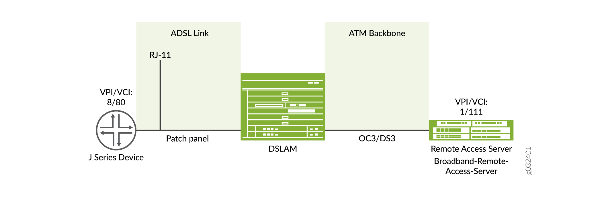
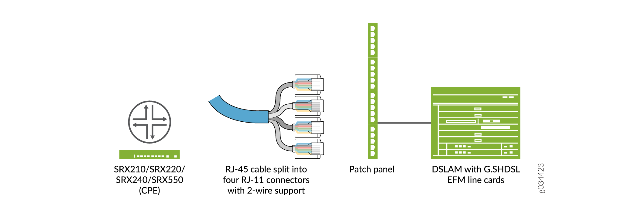
既存の Junos OS CLI で MLPPP カプセル化およびファミリー mlppp をサポートできるようにすることができます。 ADSL リンクを確立するには、最初に RJ-11 ケーブルを使用して CPE を DSLAM パッチ パネルに接続して ADSL リンクを形成し、次に OC3 または DS3 を使用して DSLAM を M Series または E Series デバイスに接続して ATM バックボーンを形成する必要があります。 |
SHDSL の機能 |
|
帯域幅 |
SHDSLは対称型で、両方向で最大2.3Mbpsの帯域幅を提供します。ADSLと互換性があるため、ケーブル間の干渉はほとんどありません。 |
パケット転送モード(PTM) |
PTMをサポートし、パケット(IP、PPP、イーサネット、MPLSなど)は、非同期転送モード(ATM)を使用する代わりにDSLリンクを介して転送されます。PTMは、Ethernet in the First Mile(EFM)IEEE 802.3ah規格に基づいています。 |
DSLの |
G.SHDSL ミニ物理インターフェイス モジュール (Mini-PIM) は、DSL ネットワーク メディア タイプへの物理接続を提供します。 |
GSHDSL 仮想回線 (VC) |
Mini-PIM あたりの VC(OAM VC を含めると最大 10)。 |
MTUサイズ |
MTU の最大サイズは 9180 バイトです。 |
GSHDSL PTM EFM |
|
ADSL2 インターフェイスでサポートされている機能とプロファイルの詳細は、 1 ポート ADSL2+ ミニ物理インターフェイス モジュールの主要機能 を参照し、SHDSL および GSHDSL インターフェイスについては、 1 ポート G.SHDSL 8 線式ミニ物理インターフェイス モジュールの概要を参照してください。
通常、ダウンストリームの帯域幅がアップストリームの帯域幅よりも大きいため、ADSL伝送は非対称です。ADSL、ADSL2、およびADSL2+回路の代表的な帯域幅を 表3に定義します。
動作モード |
川上 |
下流 |
|---|---|---|
ADSLの |
800 Kbps-1 Mbps |
8Mbps |
ADSL2の |
1-1.5 Mbps |
12 - 14 Mbps |
ADSL2+ |
1-1.5 Mbps |
24 - 25 Mbps |
ADSL2+ Annex M |
2.5 - 3 Mbps |
25Mbps |
G.SHDSL Mini-PIMの動作モードとラインレート
G.SHDSL Mini-PIMは、2線式(4ポート2線式)モード、4線式(2ポート4線式)モード、8線式(1ポート8線式)モード、およびEFMモードをサポートしています。このG.SHDSL Mini-PIMのデフォルトの動作モードは、2x 4線式です。G.SHDSLは、 表4に示す対称WAN速度を使用するすべてのデバイスでサポートされています。
モード |
Annex AおよびBを使用した対称的なWAN速度 |
Annex FおよびGを使用した対称WAN速度 |
|---|---|---|
2線式 |
2.3Mbps |
768 Kbps から 5.696 Mbps へ |
4線式 |
4.6Mbps |
1.536 Mbpsから11.392 Mbps |
8線式 |
9.2Mbps |
3.072 Mbpsから22.784 Mbps |
EFM モード |
2.3Mbps |
768 Kbps から 5.696 Mbps へ |
|
手記:
SRX210、SRX220、SRX240、SRX550デバイスでは最大16 Mbpsがサポートされています。 |
||
例:ADSLおよびSHDSLネットワークインターフェイスの設定
この例では、MLPPPを介してLFIをサポートするSRXシリーズファイアウォールでADSLおよびSHDSLインターフェイスを設定します。SRXシリーズファイアウォール上のADSLインターフェイスでMLPPPカプセル化とファミリーmlpppをサポートするには、既存のJunos OS CLIを有効にします。ネットワークデバイス間でADSLリンクを確立するには、いくつかの中間接続を使用する必要があります。まず、RJ-11ケーブルを使用してCPE(SRXシリーズファイアウォールなど)をDSLAMパッチパネルに接続し、ADSLリンクを形成します。次に、OC3 または DS3 を使用して DSLAM を M Series または E Series デバイスに接続し、ATM バックボーンを形成します。
表 5 は、ADSL および SHDSL インターフェイスの設定に使用する CLI クイック設定コマンドを示しています。
| 設定のステップ |
CLIクイック構成コマンド |
|---|---|
| ADSLインターフェイスでDHCPクライアントを設定する |
                        set interfaces at-1/0/0 encapsulation ethernet-over-atm

                        set interfaces at-1/0/0 atm-options vpi 2

                        set interfaces at-1/0/0 dsl-options operating-mode auto

                        set interfaces at-1/0/0 unit 0

                        set interfaces at-1/0/0 unit 0 encapsulation ether-over-atm-llc

                        set interfaces at-1/0/0 unit 0 vci 2.122

                        set interfaces at-1/0/0 unit 0 family inet

                        set interfaces at-1/0/0 unit 0 family inet dhcp
|
| ADSL インターフェイスの IPv6 アドレスを設定する |
                        set interfaces at-1/0/0 encapsulation ethernet-over-atm

                        set interfaces at-1/0/0 atm-options vpi 2

                        set interfaces at-1/0/0 unit 0 encapsulation ether-over-atm-llc

                        set interfaces at-1/0/0 unit 0 vci 2.118

                        set interfaces at-1/0/0 unit 0 family inet6 address 13:13::1/64
|
| ATM-over-ADSL ネットワーク インターフェイスの設定 |
                        set interfaces at-2/0/0 atm-options vpi 25 oam-liveness up-count 200 down-count 200

                        set interfaces at-2/0/0 atm-options vpi 25 oam-period 100

                        set interfaces at-1/0/0 unit 0 shaping cbr

                        set interfaces at-1/0/0 unit 0 shaping vbr peak 33000

                        set interfaces at-1/0/0 dsl-options operating-mode auto

                        set interfaces at-1/0/0 encapsulation ethernet-over-atm

                        set interfaces at-1/0/0 unit 3  encapsulation atm-nlpid oam-liveness up-count 200 down-count 200

                        set interfaces at-1/0/0 unit 3 oam-period 100

                        set interfaces at-1/0/0 unit 3 family inet

                        set interfaces at-1/0/0 unit 3 vci 35
|
| DSL インターフェイスでの CHAP の構成 |
                        set access profile A-ppp-client client client1 chap-secret my-secret

                        set interfaces at-3/0/0 unit 0 ppp-options chap access-profile A-ppp-client local-name A-at-3/0/0.0 passive
|
| ATM-over-SHDSLネットワークインターフェイスの設定 |
                        set chassis fpc 6 pic 0 shdsl pic-mode 1-port-atm

                        set interfaces at-2/0/0 atm-options vpi 25 oam-liveness up-count 200 down-count 200

                        set interfaces at-2/0/0 atm-options vpi 25 oam-period 100

                        set interfaces at-2/0/0 encapsulation ethernet-over-atm shdsl-options annex annex-a

                        set interfaces at-2/0/0 encapsulation ethernet-over-atm shdsl-options line-rate auto

                        set interfaces at-2/0/0 encapsulation ethernet-over-atm shdsl-options loopback local

                        set interfaces at-2/0/0 encapsulation ethernet-over-atm shdsl-options snr-margin current 5 snext 5

                        set interfaces at-2/0/0 unit 3 encapsulation atm-nlpid

                        set interfaces at-2/0/0 unit 3 oam-liveness up-count 200 down-count 200

                        set interfaces at-2/0/0 unit 3 oam-period 100

                        set interfaces at-2/0/0 unit 3 oam-period 100

                        set interfaces at-2/0/0 unit 3 vci 35
|
ADSLインターフェイスでDHCPクライアントを設定する
この例では、ATMインターフェイスを at-1/0/0として設定します。次に、論理インターフェイスを unit 0 に設定し、ファミリープロトコルタイプを inetに指定します。最後に、DHCPクライアントを設定します。ADSLインターフェイスでDHCPクライアントを設定するには:
設定の出力を表示するには、 show interfaces at-1/0/0 コマンドを使用します。
ADSLインターフェイスでIPv6アドレスを設定する
ADSL インターフェイスで IPv6 アドレスを設定するには:
-
カプセル化タイプを設定します。
[edit] user@host# set interfaces at-1/0/0 encapsulation ethernet-over-atm -
附属書タイプを指定します。
[edit] user@host# set interfaces at-1/0/0 atm-options vpi 2 -
論理ユニットのカプセル化を設定します。
[edit] user@host# set interfaces at-1/0/0 unit 0 encapsulation ether-over-atm-llc -
VCI 値を設定します。
[edit] user@host# set interfaces at-1/0/0 unit 0 vci 2.118 -
ファミリープロトコルタイプを設定し、IPv6アドレスを割り当てます。
[edit] user@host# set interfaces at-1/0/0 unit 0 family inet6 address 13:13::1/64
設定の出力を表示するには、 show interfaces at-1/0/0 コマンドを使用します。
ATM-over-ADSL ネットワーク インターフェイスの設定
この例では、ADSL Annex A または Annex B PIM を搭載したデバイスを使用して、ポイントツーポイント接続を介して DSLAM にネットワーク トラフィックを送信する方法を示します。この例では、DSL動作モードタイプをautoに設定して、ADSLインターフェイスがDSLAMと設定を自動ネゴシエートするようにします。
この例では、at-2/0/0 と呼ばれる ATM インターフェイスを作成する方法を示しています。インターフェイスの物理プロパティの値は比較的低く保たれ、ATM VPI は 25 に設定されます。OAM のダウン カウントとアップ カウントの両方が 200 セルに設定されます。OAM 期間は 100 秒に設定されます。
この例では、CoS をサポートするために ATM インターフェイスでトラフィックシェーピング値を設定する方法も示しています。 CBR は、接続期間中、セルの伝送速度を安定させるために有効です。さらに、データ パケット転送の VBR ピークは 33,000 に設定されます。
この例では、PPP over Ethernet IPv4トラフィックをサポートするために、カプセル化モードをethernet-over-atmに設定します。また、論理インターフェイス(ユニット3)も設定します。論理インターフェイスは、ATM NLPIDカプセル化を使用します。物理インターフェイスと同様に、論理インターフェイスでもOAMダウンカウントとアップカウントは200セルに設定され、OAM期間は100秒に設定されます。ファミリー プロトコルは inet に設定され、VCI は 35 に設定されます。
SRXシリーズファイアウォールでは、CPEがANSI-DMTモードで設定され、COが自動モードで設定されている場合、ATMインターフェイスが立ち上がるまでに5分以上かかります。これは、ADSL Mini-PIMで実行されている現在のファームウェアバージョンの制限により、ALU 7300 DSLAMでのみ発生します。
デバイスのATM-over-ADSLネットワークインターフェイスを設定するには、次の手順に従います。
-
ATM インターフェイスを作成します。
[edit] user@host# edit interfaces at-2/0/0 -
ATMインターフェイスの物理プロパティを設定します。
[edit interfaces at-2/0/0] user@host# set atm-options vpi 25 user@host# set atm-options vpi 25 oam-liveness up-count 200 down-count 200 user@host# set atm-options vpi 25 oam-period 100 -
イーサネット インターフェイスの CBR 値と VBR 値を指定します。
[edit] user@host# edit interfaces at-1/0/0 unit 0 user@host# set shaping cbr user@host# set shaping vbr peak 33000 -
DSL 動作モードの種類を設定します。
[edit interfaces at-1/0/0.0] user@host# set dsl-options operating-mode auto -
カプセル化タイプを設定します。
[edit interfaces at-1/0/0] user@host# set encapsulation ethernet-over-atm -
論理ユニットのカプセル化を設定します。
[edit interfaces at-1/0/0 unit 3] user@host# set encapsulation atm-nlpid -
ATM仮想回線のOAM活性値を設定します。
[edit interfaces at-1/0/0 unit 3] user@host# set oam-liveness up-count 200 down-count 200 -
OAM期間を指定します。
[edit interfaces at-1/0/0 unit 3] user@host# set oam-period 100 -
ファミリー プロトコル タイプを設定します。
[edit interfaces at-1/0/0 unit 3] user@host# set family inet -
VCI 値を設定します。
[edit interfaces at-1/0/0 unit 3]
user@host# set vci 35
設定の出力を表示するには、 show コマンドを使用します。
MLPPP-over-ADSLインターフェイスの設定
この例では、インターフェイス at-5/0/0にカプセル化をatm-mlppp-llcとして設定します。次に、ファミリー MLPPP バンドルを lsq-0/0/0.1 として設定します。
図 1 は、MLPPP-over-ADSL エンドツーエンド接続の典型的な例を示しています。
ADSL インターフェイスで MLPPP を設定するには:
-
インターフェイスを設定します。
[edit] user@host# edit interfaces at-5/0/0 unit 0 -
MLPPPカプセル化を設定します。
[edit interfaces at-5/0/0 unit 0] user@host# set encapsulation atm-mlppp-llc -
ファミリー MLPPP を指定します。
[edit interfaces at-5/0/0 unit 0] user@host# set family mlppp bundle lsq-0/0/0.1 -
デバイスの設定が完了したら、設定をコミットします。
[edit]
user@host# commit
設定の出力を表示するには、 show コマンドを使用します。
DSLインターフェイスでのCHAPの設定
この例では、CHAP アクセス プロファイルを指定し、 at-3/0/0 というインターフェイスを作成します。ATM-over-ADSLまたはATM-over-SHDSLインターフェイスでCHAPを設定し、クライアントリストとアクセスパラメータを含むA-ppp-clientという一意のプロファイル名を指定します。次に、CHAP で使用する A-at-3/0/0.0 という一意のホスト名を指定します。最後に、パッシブ オプションを設定して、受信 CHAP パケットを処理します。ATM-over-ADSLまたはATM-over-SHDSLインターフェイスのいずれかでCHAPを設定するには、次の手順に従います。
-
CHAPアクセスプロファイルを定義します。
[edit] user@host# set access profile A-ppp-client client client1 chap-secret my-secret -
インターフェイスを作成します。
[edit] user@host# edit interfaces at-3/0/0 unit 0 -
CHAPを構成し、一意のプロファイル名を指定します。
[edit interfaces at-3/0/0 unit 0] user@host# set ppp-options chap access-profile A-ppp-client -
一意のホスト名を指定します。
[edit interfaces at-3/0/0 unit 0] user@host# set ppp-options chap local-name A-at-3/0/0.0 -
受信CHAPパケットのみを処理するように オプションを設定します。
[edit interfaces at-3/0/0 unit 0]
user@host# set ppp-options chap passive
設定の出力を表示するには、 show コマンドを使用します。
ATM-over-SHDSLネットワークインターフェイスの設定
この例では、必要に応じて、G.SHDSL インターフェイスで ATM-over-SHDSL モードを設定します。 at-2/0/0 と呼ばれるインターフェイスを作成し、インターフェイスの物理プロパティを設定します。カプセル化タイプと付属書タイプを設定します。ATM-over-SHDSL インターフェイスの SHDSL ライン レートと、SHDSL 接続の整合性をテストするためのループバック アドレスを指定します。次に、SNRマージンを設定し、論理インターフェイスを設定し、ATM-over-SHDSL論理ユニットのカプセル化を設定します。
さらに、ATM仮想回線のOAMライブネス値を設定し、OAM期間を設定し、最後にファミリープロトコルタイプinetを追加し、VCI値を設定します。デバイスの ATM-over-SHDSL ネットワーク インターフェイスを設定するには、次の手順に従います。
-
G.SHDSL インターフェイスで ATM-over-SHDSL モードを設定します。
[edit] user@host# set chassis fpc 6 pic 0 shdsl pic-mode 1-port-atm -
インターフェイスを作成します。
[edit] user@host# edit interfaces at-2/0/0 -
インターフェイスの物理プロパティを設定します。
[edit interfaces at-2/0/0] user@host# set atm-options vpi 25 user@host# set atm-options vpi 25 oam-liveness up-count 200 down-count 200 user@host# set atm-options vpi 25 oam-period 100 -
カプセル化タイプを設定します。
[edit interfaces at-2/0/0] user@host# set encapsulation ethernet-over-atm -
附属書の種類を設定します。
[edit] user@host# edit interfaces at-2/0/0 shdsl-options user@host# set annex annex-a -
SHDSLラインレートを設定します。
[edit interfaces at-2/0/0 shdsl-options] user@host# set line-rate auto -
SHDSL接続の整合性をテストするためのループバックオプションを設定します。
[edit interfaces at-2/0/0 shdsl-options] user@host# set loopback local -
信号対雑音比マージンを設定します。
[edit interfaces at-2/0/0 shdsl-options] user@host# set snr-margin current 5 user@host# set snr-margin snext5 -
論理インターフェイスを設定します。
[edit] user@host# edit interfaces at-2/0/0 unit 3 -
論理ユニットのカプセル化を設定します。
[edit interfaces at-2/0/0 unit 3] user@host# set encapsulation atm-nlpid -
ATM仮想回線のOAM活性値を設定します
[edit interfaces at-2/0/0 unit 3] user@host# set oam-liveness up-count 200 down-count 200 -
OAM 期間を設定します。
[edit interfaces at-2/0/0 unit 3] user@host# set oam-period 100 -
ファミリープロトコルタイプを追加します。
[edit interfaces at-2/0/0 unit 3] user@host# set family inet -
VCI 値を設定します。
[edit interfaces at-2/0/0 unit 3]
user@host# set vci 35
設定の出力を表示するには、 show コマンドを使用します。
検証
ADSLおよびSHDSLインターフェイスで設定されたパラメータに関する情報を表示します。
-
DHCP オプションが設定されていることを確認するには、
run show system services dhcp clientコマンドを使用します。user@host#run show system services dhcp client Logical Interface name at-1/0/0.0 Hardware address 00:1f:12:e4:71:38 Client status bound Address obtained 10.40.1.2 Update server disabled Lease obtained at 2011-05-03 04:58:10 PDT Lease expires at 2011-05-04 04:58:10 PDT DHCP options: Name: server-identifier, Value: 10.40.1.1 Code: 1, Type: ip-address, Value: 255.255.255.0 Name: name-server, Value: [ 192.168.5.68, 192.168.60.131, 172.17.28.100, 172.17.28.101 ] Name: domain-name, Value: englab.juniper.netインターフェイスのステータスとトラフィック統計情報を確認するには、
show interface terseコマンドを使用し、リモートエンドIPアドレスにpingパケットを送信して、エンドツーエンドのデータパス接続をテストします。user@host#run show interfaces at-1/0/0 terse Interface Admin Link Proto Local Remote at-1/0/0 up up at-1/0/0.0 up up inet 10.40.1.2/24 at-1/0/0.32767 up upuser@host#run ping 10.40.1.1 count 100 rapid PING 10.40.1.1 (10.40.1.1): 56 data bytes !!!!!!!!!!!!!!!!!!!!!!!!!!!!!!!!!!!!!!!!!!!!!!!!!!!!!!!!!!!!!!!!!!!!!!!!!!!!!!!!!!!!!!!!!!!!!!!!!!!! --- 10.40.1.1 ping statistics --- 100 packets transmitted, 100 packets received, 0% packet loss round-trip min/avg/max/stddev = 20.086/26.404/61.723/6.194 ms -
ADSLインターフェイスのプロパティが設定されていることを確認するには、
show ipv6 neighborsコマンドを使用します。出力は、インターフェイス情報の概要を示しています。user@host> show ipv6 neighbors IPv6 Address Linklayer Address State Exp Rtr Secure Interface 10:1::2 00:00:0a:00:00:00 reachable 17 yes no reth0.0 13:13::1 00:19:e2:4b:61:83 stale 1197 yes no at-1/0/0.0 12:12::2 00:19:e2:4b:61:83 stale 1188 yes no at-3/0/0.0
IPv6 Addressフィールドには、インターフェイスで設定されたIPv6アドレスが表示されます。 -
ADSLインターフェイスのプロパティを確認するには、
show interfaces at-1/0/0 extensiveコマンドを使用します。user@host> show interfaces at-1/0/0 extensive Physical interface: at-1/0/0, Enabled, Physical link is Up Interface index: 141, SNMP ifIndex: 49, Generation: 142 Link-level type: ATM-PVC, MTU: 4482, Clocking: Internal, ADSL mode, Speed: ADSL, Loopback: None Device flags : Present Running Link flags : None CoS queues : 8 supported, 8 maximum usable queues Hold-times : Up 0 ms, Down 0 ms Current address: 00:05:85:c3:17:f4 Last flapped : 2008-06-26 23:11:09 PDT (01:41:30 ago) Statistics last cleared: Never Traffic statistics: Input bytes : 0 0 bps Output bytes : 0 0 bps Input packets: 0 0 pps Output packets: 0 0 pps Input errors: Errors: 0, Drops: 0, Invalid VCs: 0, Framing errors: 0,Policed discards: 0, L3 incompletes: 0, L2 channelerrors: 0, L2 mismatch timeouts: 0, Resource errors: 0 Output errors: Carrier transitions: 3, Errors: 0, Drops: 0, Aged packets: 0, MTU errors: 0, Resource errors: 0 ADSL alarms : None ADSL defects : None ADSL media: Seconds Count State LOF 1 1 OK LOS 1 1 OK LOM 0 0 OK LOP 0 0 OK LOCDI 0 0 OK LOCDNI 0 0 OK ADSL status: Modem status : Showtime (Adsl2plus) DSL mode : Auto Annex A Last fail code: None Subfunction : 0x00 Seconds in showtime : 6093 ADSL Chipset Information: ATU-R ATU-C Vendor Country : 0x0f 0xb5 Vendor ID : STMI IFTN Vendor Specific: 0x0000 0x70de ADSL Statistics: ATU-R ATU-C Attenuation (dB) : 0.0 0.0 Capacity used(%) : 100 92 Noise margin(dB) : 7.5 9.0 Output power (dBm) : 10.0 12.5 Interleave Fast Interleave Fast Bit rate (kbps) : 0 24465 0 1016 CRC : 0 0 0 0 FEC : 0 0 0 0 HEC : 0 0 0 0 Received cells : 0 49 Transmitted cells : 0 0 ATM status: HCS state: Hunt LOC : OK ATM Statistics: Uncorrectable HCS errors: 0, Correctable HCS errors: 0,Tx cell FIFO overruns: 0,Rx cell FIFO overruns: 0,Rx cell FIFO underruns: 0, Input cell count: 49, Output cell count: 0,Output idle cell count: 0,Output VC queue drops: 0Input no buffers: 0, Input length errors: 0, Input timeouts: 0, Input invalid VCs: 0, Input bad CRCs: 0, Input OAM cell no buffers: 0 Packet Forwarding Engine configuration: Destination slot: 1 Direction : Output CoS transmit queue Bandwidth Buffer Priority Limit % bps % usec 0 best-effort 95 7600000 95 0 low none 3 network-control 5 400000 5 0 low none But for ADSL MiniPim TI chipset does not send ADSL Chipset Information. Also Adsl minipim does not send any alarms. So we can't show alarm stats for minipim. So following information will not be displayed in Minipim case. ADSL alarms : None ADSL defects : None ADSL media: Seconds Count State LOF 1 1 OK LOS 1 1 OK LOM 0 0 OK LOP 0 0 OK LOCDI 0 0 OK LOCDNI 0 0 OK ADSL Chipset Information: ATU-R ATU-C Vendor Country : 0x0f 0xb5 Vendor ID : STMI IFTN Vendor Specific: 0x0000 0x70de出力は、インターフェイス情報の概要を示しています。
ATM-over-ADSL インターフェイスの PPPoA 設定が正しいことを確認するには、
show interfaces at-1/0/0コマンドとshow accessコマンドを使用します。 -
MLPPP-over-ADSL インターフェイスの設定が正しいことを確認するには、
show interfaces at-5/0/0コマンドを使用します。 -
ADSLインターフェイスのプロパティが有効になっていることを確認するには、
show interfaces at-3/0/0 extensiveコマンドを使用します。user@host> show interfaces at-3/0/0 extensive Physical interface: at-3/0/0, Enabled, Physical link is Up Interface index: 141, SNMP ifIndex: 49, Generation: 142 Link-level type: ATM-PVC, MTU: 4482, Clocking: Internal, ADSL mode, Speed: ADSL, Loopback: None Device flags : Present Running Link flags : None CoS queues : 8 supported, 8 maximum usable queues Hold-times : Up 0 ms, Down 0 ms Current address: 00:05:85:c3:17:f4 Last flapped : 2008-06-26 23:11:09 PDT (01:41:30 ago) Statistics last cleared: Never Traffic statistics: Input bytes : 0 0 bps Output bytes : 0 0 bps Input packets: 0 0 pps Output packets: 0 0 pps Input errors: Errors: 0, Drops: 0, Invalid VCs: 0, Framing errors: 0,Policed discards: 0, L3 incompletes: 0, L2 channelerrors: 0, L2 mismatch timeouts: 0, Resource errors: 0 Output errors: Carrier transitions: 3, Errors: 0, Drops: 0, Aged packets: 0, MTU errors: 0, Resource errors: 0 ADSL alarms : None ADSL defects : None ADSL media: Seconds Count State LOF 1 1 OK LOS 1 1 OK LOM 0 0 OK LOP 0 0 OK LOCDI 0 0 OK LOCDNI 0 0 OK ADSL status: Modem status : Showtime (Adsl2plus) DSL mode : Auto Annex A Last fail code: None Subfunction : 0x00 Seconds in showtime : 6093 ADSL Chipset Information: ATU-R ATU-C Vendor Country : 0x0f 0xb5 Vendor ID : STMI IFTN Vendor Specific: 0x0000 0x70de ADSL Statistics: ATU-R ATU-C Attenuation (dB) : 0.0 0.0 Capacity used(%) : 100 92 Noise margin(dB) : 7.5 9.0 Output power (dBm) : 10.0 12.5 Interleave Fast Interleave Fast Bit rate (kbps) : 0 24465 0 1016 CRC : 0 0 0 0 FEC : 0 0 0 0 HEC : 0 0 0 0 Received cells : 0 49 Transmitted cells : 0 0 ATM status: HCS state: Hunt LOC : OK ATM Statistics: Uncorrectable HCS errors: 0, Correctable HCS errors: 0,Tx cell FIFO overruns: 0,Rx cell FIFO overruns: 0,Rx cell FIFO underruns: 0, Input cell count: 49, Output cell count: 0,Output idle cell count: 0,Output VC queue drops: 0Input no buffers: 0, Input length errors: 0, Input timeouts: 0, Input invalid VCs: 0, Input bad CRCs: 0, Input OAM cell no buffers: 0 Packet Forwarding Engine configuration: Destination slot: 1 Direction : Output CoS transmit queue Bandwidth Buffer Priority Limit % bps % usec 0 best-effort 95 7600000 95 0 low none 3 network-control 5 400000 5 0 low none But for ADSL MiniPim TI chipset does not send ADSL Chipset Information. Also Adsl minipim does not send any alarms. So we can't show alarm stats for minipim. So following information will not be displayed in Minipim case. ADSL alarms : None ADSL defects : None ADSL media: Seconds Count State LOF 1 1 OK LOS 1 1 OK LOM 0 0 OK LOP 0 0 OK LOCDI 0 0 OK LOCDNI 0 0 OK ADSL Chipset Information: ATU-R ATU-C Vendor Country : 0x0f 0xb5 Vendor ID : STMI IFTN Vendor Specific: 0x0000 0x70deATM-over-ADSL インターフェイスの PPPoA 設定が正しいことを確認するには、
show interfaces at-3/0/0コマンドとshow accessコマンドを使用します。ATM-over-SHDSL の設定が正しいことを確認するには、
show interfaces at-3/0/0 extensiveコマンドを使用します。user@host> show interfaces at-3/0/0 extensive Physical interface: at-3/0/0, Enabled, Physical link is Up Interface index: 141, SNMP ifIndex: 23, Generation: 48 Link-level type: ATM-PVC, MTU: 4482, Clocking: Internal, ADSL mode, Speed: ADSL, Loopback: None Device flags : Present Running Link flags : None CoS queues : 8 supported Hold-times : Up 0 ms, Down 0 ms Current address: 00:05:85:c7:44:3c Last flapped : 2005-05-16 05:54:41 PDT (00:41:42 ago) Statistics last cleared: Never Traffic statistics: Input bytes : 4520 0 bps Output bytes : 39250 0 bps Input packets: 71 0 pps Output packets: 1309 0 pps Input errors: Errors: 0, Drops: 0, Invalid VCs: 0, Framing errors: 0, Policed discards: 0, L3 incompletes: 0, L2 channel errors: 1, L2 mismatch timeouts: 0, Resource errors: 0 Output errors: Carrier transitions: 3, Errors: 0, Drops: 0, Aged packets: 0, MTU errors: 0, Resource errors: 0 Queue counters: Queued packets Transmitted packets Dropped packets 0 best-effort 4 4 0 1 expedited-fo 0 0 0 2 assured-forw 0 0 0 3 network-cont 2340 2340 0 SHDSL alarms : None SHDSL defects : None SHDSL media: Seconds Count State LOSD 239206 2 OK LOSW 239208 1 OK ES 3 1 OK SES 0 0 OK UAS 3 1 OK SHDSL status: Line termination :STU-R Annex :Annex B Line Mode :2–wire Modem Status :Data Last fail code :0 Framer mode :ATM Dying Gasp :Enabled Chipset version :1 Firmware version :R3.0 SHDSL Statistics: Loop Attenuation (dB) :0.600 Transmit power (dB) :8.5 Receiver gain (dB) :21.420 SNR sampling (dB) :39.3690 Bit rate (kbps) :2304 Bit error rate :0 CRC errors :0 SEGA errors :1 LOSW errors :0 Received cells :1155429 Transmitted cells :1891375 HEC errors :0 Cell drop :0
例:G.SHDSL インターフェイスの設定
この例では、SRXシリーズファイアウォールでG.SHDSLインターフェイスを設定する方法を示しています。
GSHDSL インターフェースを設定するには:
-
G.SHDSL インターフェイスでワイヤ モードを指定します。デフォルトのワイヤ モードは 4 線(2 ポート、4 線)です。
-
附属書タイプを指定します。デフォルトの附属書タイプは
autoです。 -
SHDSLラインレート(SHDSL接続上のデータの伝送速度)を指定します。デフォルトのラインレートは
autoです。 -
カプセル化タイプを指定します。
pt-インターフェイスは、カプセル化タイプを必要としません。 -
カプセル化タイプを設定します。
開始する前に、以下を実行します。
-
必要に応じてネットワークインターフェイスを設定します。 イーサネット インターフェイスについてを参照してください。
-
G.SHDSL Mini-PIM を SRX210 シャーシの最初のスロットに取り付けます。
-
SRX210 デバイスを DSLAM(IP、DSLAM、ATM DSLAM)に接続します。
図 2 は、2X4 線モードで動作する G.SHDSL Mini-PIM のトポロジを示しています。
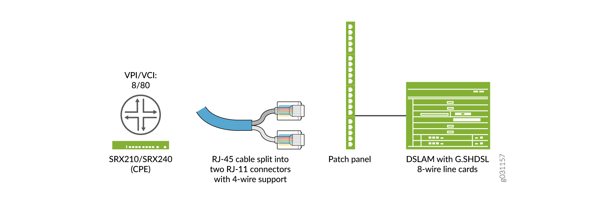
図 3 は、4X2 線式モードで動作する G.SHDSL Mini-PIM のトポロジーを示しています。
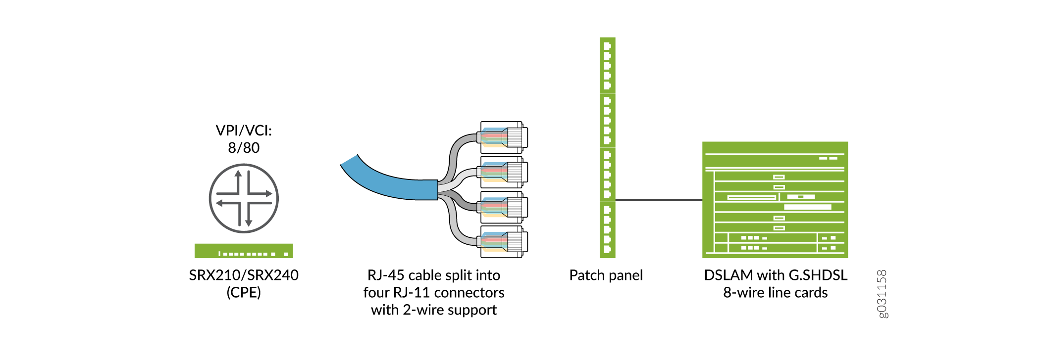
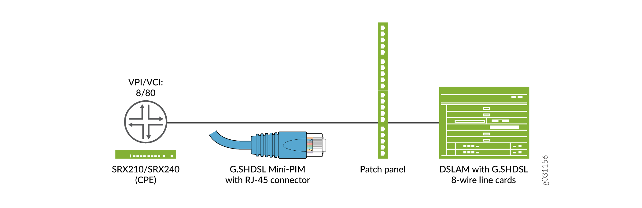
図 4 は、1X8 線モードで動作する G.SHDSL Mini-PIM のトポロジを示しています。
動作ワイヤモード(2線式、4線式、または8線式)と、 表6に記載されている対応するCLIコードを決定します。
| ワイヤ モード設定 |
CLIコード |
|---|---|
| 2x4線式構成 |
手記:
2x4線式構成は、デフォルトの構成および動作です。 |
| 4x2線式構成 |
|
| 1x8線式構成 |
|
ワイヤ モードを 8 線に設定すると、1 つの物理インターフェイス(IFD)が作成されます。同様に、4線式モードと2線式モードでは、それぞれ2つのIFDと4つのIFDが作成されます。
この例では、次のようになります。
-
最初に、基本的な G.SHDSL インターフェイスを設定します。動作ワイヤモードを2-port-atm、ラインレートを4096、annexタイプを
annex-aに設定します。 -
デバイスがIP DSLAMに接続されているときに、G.SHDSLインターフェイスを設定します。カプセル化のタイプを ethernet-over-atm に、ATM VPI オプションを 0 に設定します。G.SHDSL論理インターフェイスのカプセル化のタイプを
ether-over-atm-llcとして設定し、ATM VCIオプションを0.60に設定します。また、論理インターフェイスのインターフェイスアドレスを 10.1.1.1/24 に設定します。 -
デバイスが ATM DSLAM に接続されている場合、G.SHDSL インターフェイスを設定します。ATM VPI を 0 に設定し、カプセル化のタイプを
ppp-over-ether-over-atm-llcに設定します。PAPアクセスプロファイル、local-name、およびlocal-passwordを使用してPPPoEインターフェイスを指定します。受信PAPパケットを処理するパッシブオプションを設定し、論理インターフェイスをPPPoEセッションの基盤となるインターフェイスとしてat-1/0/0.0に設定します。PPPoE セッション終了後に再接続するまで待機する秒数を 120 に設定します。PPPoEインターフェイスのクライアントとして論理インターフェイスを指定し、リモートエンドとのネゴシエーションによりIPアドレスを取得します。 -
G.SHDSL インターフェイスの ATM 経由の PPPoA を設定します。カプセル化のタイプを
atm-pvcに、ATM VPI を 0 に設定します。論理インターフェイスで PPP over ATM アダプテーション レイヤー 5(AAL5)LLC(論理リンク制御)のカプセル化のタイプを設定し、ATM VCI を 122 に設定します。CHAP アクセス プロファイルを使用して PPPoA インターフェイスを juniper として設定し、CHAP インターフェイスのlocal-nameを srx-210 に設定します。最後に、リモートエンドとのネゴシエーションによってIPアドレスを取得します。
表 7に、GSHDSL インターフェースの設定に使用する CLI クイック構成コマンドを示します。
| 設定のステップ |
CLIクイック構成コマンド |
|---|---|
| 基本的な G.SHDSL インターフェイスを設定します |
                        set chassis fpc 1 pic 0 shdsl pic-mode 2-port-atm

                        set interfaces at-1/0/0 shdsl-options line-rate 4096 annex annex-a
|
| IP DSLAM 接続時の G.SHDSL インターフェイスの設定 |
                        set interfaces at-1/0/0 encapsulation ethernet-over-atm

                        set interfaces at-1/0/0 atm-options vpi 0

                        set interfaces at-1/0/0 unit 0 encapsulation ether-over-atm-llc vci 0.60

                        set interfaces at-1/0/0 unit 0  family inet address 10.1.1.1/24
|
| ATM DSLAM 接続時の G.SHDSL インターフェイスの設定 |
                        set interfaces at-1/0/0 encapsulation atm-pvc atm-options vpi 0

                        set interfaces at-1/0/0 unit 0 encapsulation atm-snap vci 0.65

                        set interfaces at-1/0/0 unit 0 family inet address 10.2.1.1/24
|
| G.SHDSL インターフェイスの ATM 経由の PPPoE の設定 |
                        set interfaces at-1/0/0 encapsulation ethernet-over-atm  atm-options vpi 0

                        set interfaces at-1/0/0 unit 0 encapsulation ppp-over-ether-over-atm-llc vci 0.35

                        set interfaces pp0 unit 0 ppp-options pap access-profile pap_prof local-name srx-210

                        set interfaces pp0 unit 0 ppp-options pap local-password  "$9$0tLw1SeN-woJDSr-wY2GU69Cp1RSre"

                        set interfaces pp0 unit 0 ppp-options pap passive

                        set interfaces pp0 unit 0 pppoe-options underlying-interface at-1/0/0.0

                        set interfaces pp0 unit 0 pppoe-options auto-reconnect 120 client

                        set interfaces pp0 unit 0 family inet negotiate-address
|
| G.SHDSL インターフェイスの ATM 経由の PPPoA の設定 |
                        set interfaces at-1/0/0 encapsulation atm-pvc atm-options vpi 0

                        set interfaces at-1/0/0 unit 0 encapsulation atm-ppp-llc vci 1.122

                        set interfaces at-1/0/0 unit 0 ppp-options chap access-profile juniper local-name srx-210

                        set interfaces at-1/0/0 unit 0 family inet negotiate-address
|
| EFM PICモードでの基本的なG.SHDSLインターフェイスの協調図 |
                        set chassis fpc 1 pic 0 shdsl pic-mode efm

                        set interfaces pt-1/0/0 shdsl-options annex annex-g

                        set interfaces pt-1/0/0 shdsl-options line-rate 5696

                        set interfaces pt-1/0/0 unit 0 family inet address 10.10.10.1/24
|
| G.SHDSL EFMインターフェイスのPPPoEとVLANを設定します |
                        set interfaces pt-1/0/0 unit 0 encapsulation ppp-over-ether

                        set interfaces pp0 unit 0 ppp-options pap access-profile pap_prof local-name srx-210

                        set interfaces pp0 unit 0 ppp-options pap local-password  "$9$0tLw1SeN-woJDSr-wY2GU69Cp1RSre"

                        set interfaces pp0 unit 0 ppp-options pap passive

                        set interfaces pp0 unit 0 pppoe-options underlying-interface pt-1/0/0.0

                        set interfaces pp0 unit 0 pppoe-options auto-reconnect 120 client

                        set interfaces pp0 unit 0 family inet negotiate-address
|
| EFM PICモードでの基本的なG.SHDSLインターフェイスの設定 |
                        set chassis fpc 1 pic 0 shdsl pic-mode efm

                        set interfaces pt-1/0/0 shdsl-options annex annex-g

                        set interfaces pt-1/0/0 shdsl-options line-rate 5696

                        set interfaces pt-1/0/0 unit 0 family inet address 10.10.10.1/24
|
| G.SHDSL EFM インターフェイスの PPPoE と VLAN の設定 |
                        set interfaces pt-1/0/0 unit 0 encapsulation ppp-over-ether

                        set interfaces pp0 unit 0 ppp-options pap access-profile pap_prof local-name srx-210

                        set interfaces pp0 unit 0 ppp-options pap local-password  "$9$0tLw1SeN-woJDSr-wY2GU69Cp1RSre"

                        set interfaces pp0 unit 0 ppp-options pap passive

                        set interfaces pp0 unit 0 pppoe-options underlying-interface pt-1/0/0.0

                        set interfaces pp0 unit 0 pppoe-options auto-reconnect 120 client

                        set interfaces pp0 unit 0 family inet negotiate-address
|
基本的なG.SHDSLインターフェイスの設定
CLI クイック構成コマンドを表示するには、 表 7 を参照してください。SRX210デバイスで基本的なG.SHDSLインターフェイスを設定するには、次の手順に従います。
設定の出力を表示するには、 show interfaces at-1/0/0 コマンドを使用します。
IP DSLAM に接続された G.SHDSL インターフェイスの設定
デバイスがIP DSLAMに接続されているときに、SRX210デバイスのG.SHDSLインターフェイスを設定するには、次の手順に従います。
-
インターフェイスを作成します。
[edit] user@host# edit interfaces at-1/0/0 -
カプセル化のタイプを指定します。
[edit interfaces at-1/0/0] user@host# set encapsulation ethernet-over-atm -
ATM VPIオプションを設定します。
[edit interfaces at-1/0/0] user@host# set atm-options vpi 0 -
論理インターフェイスのカプセル化のタイプを指定します。
[edit interfaces at-1/0/0 ] user@host# edit unit 0 user@host# set encapsulation ether-over-atm-llc -
論理インターフェイスの ATM VCI オプションを設定します。
[edit interfaces at-1/0/0 unit 0] user@host# set vci 0.60 -
インターフェイス アドレスを設定します。
[edit interfaces at-1/0/0 unit 0]
user@host# set family inet address 10.1.1.1/24
設定の出力を表示するには、 show interfaces at-1/0/0 コマンドを使用します。
ATM DSLAM に接続された時の G.SHDSL インターフェイスの設定
デバイスがATM DSLAMに接続されているときに、SRX210デバイスのG.SHDSLインターフェイスを設定するには、次の手順に従います。
-
インターフェイスを作成します。
[edit] user@host# edit interfaces at-1/0/0 -
カプセル化のタイプを指定します。
[edit interfaces at-1/0/0] user@host# set encapsulation atm-pvc -
ATM VPIオプションを設定します。
[edit interfaces at-1/0/0] user@host# set atm-options vpi 0 -
論理インターフェイスのカプセル化のタイプを指定します。
[edit interfaces at-1/0/0] user@host# edit unit 0 user@host# set encapsulation atm-snap -
ATM VCI オプションを設定します。
[edit interfaces at-1/0/0 unit 0] user@host# set vci 0.65 -
インターフェイス アドレスを設定します。
[edit interfaces at-1/0/0 unit 0]
user@host# set family inet address 10.2.1.1/24
設定の出力を表示するには、 show interfaces at-1/0/0 コマンドを使用します。
G.SHDSLインターフェイス用のATM上のPPPoEの設定
G.SHDSL インターフェイスで ATM 経由で PPPoE を設定するには、次の手順に従います。
-
インターフェイスを作成します。
[edit] user@host# edit interfaces at-1/0/0 -
カプセル化のタイプを指定します。
[edit interfaces at-1/0/0] user@host# set encapsulation ethernet-over-atm -
ATM VPIオプションを設定します。
[edit interfaces at-1/0/0] user@host# set atm-options vpi 0 -
論理インターフェイスでのカプセル化のタイプを指定します。
[edit interfaces at-1/0/0] user@host# edit unit 0 user@host# set encapsulation ppp-over-ether-over-atm-llc -
ATM VCI オプションを設定します。
[edit interfaces at-1/0/0 unit 0] user@host# set vci 0.35 -
PAPアクセスプロファイルを使用してPPPoEインターフェイスを設定します。
[edit] user@host# edit interfaces pp0 unit 0 ppp-options pap user@host# set access-profile pap_prof -
PAP インターフェイスのローカル名を設定します。
[edit interfaces pp0 unit 0 ppp-options pap] user@host# set local-name srx-210 -
PAPインターフェイスのローカルパスワードを設定します。
[edit interfaces pp0 unit 0 ppp-options pap] user@host# set local-password "$9$0tLw1SeN-woJDSr-wY2GU69Cp1RSre" -
パッシブ オプションを設定して、受信 PAP パケットを処理します。
[edit interfaces pp0 unit 0 ppp-options pap] user@host# set passive -
PPPoEセッションの基礎となるインターフェイスとして論理インターフェイスを指定します。
[edit] user@host# edit interfaces pp0 unit 0 pppoe-options user@host# set underlying-interface at-1/0/0.0 -
秒数を指定します。
[edit interfaces pp0 unit 0 pppoe-options] user@host# set auto-reconnect 120 -
論理インターフェイスをPPPoEインターフェイスのクライアントとして設定します。
[edit interfaces pp0 unit 0 pppoe-options] user@host# set client -
リモートエンドとのネゴシエーションにより、IPアドレスを取得します。
[edit]
user@host# edit interfaces pp0 unit 0
user@host# set family inet negotiate-address
show interfaces at-1/0/0 コマンドと show interfaces pp0 コマンドを使用して、設定の出力を確認します。
G.SHDSLインターフェイス用のATM経由PPPoAの設定
G.SHDSL インターフェイスで ATM 経由で PPPoA を設定するには、次の手順に従います。
-
インターフェイスを作成します。
[edit] user@host# edit interfaces at-1/0/0 -
カプセル化のタイプを指定します。
[edit interfaces at-1/0/0] user@host# set encapsulation atm-pvc -
ATM VPIオプションを設定します。
[edit interfaces at-1/0/0] user@host# set atm-options vpi 0 -
G.SHDSL論理インターフェイスでのカプセル化のタイプを指定します。
[edit] user@host# edit interfaces at-1/0/0 unit 0 user@host# set encapsulation atm-ppp-llc -
ATM VCI オプションを設定します。
[edit interfaces at-1/0/0 unit 0] user@host# set vci 1.122 -
CHAP アクセス プロファイルを使用して PPPoA インターフェイスを設定します。
[edit] user@host# edit interfaces at-1/0/0 unit 0 ppp-options chap user@host# set access-profile juniper -
CHAP インターフェイスのローカル名を構成します。
[edit interfaces at-1/0/0 unit 0 ppp-options chap] user@host# set local-name srx-210 -
リモートエンドとのネゴシエーションにより、IPアドレスを取得します。
[edit]
user@host# edit interfaces at-1/0/0 unit 0
user@host# set family inet negotiate-address
設定の出力を表示するには、 show interfaces at-1/0/0 コマンドを使用します。
EFM モードでの G.SHDSL インターフェイスの設定
この例では、次のようになります。
-
まず、動作ワイヤ モードを efm に、ライン レートを auto に、annex タイプを annex-auto に設定して、基本的な G.SHDSL インターフェイスを設定します。
-
次に、デバイスが EFM IP DSLAM に接続されているときに G.SHDSL インターフェイスを設定します。論理インターフェイスを 10.10.10.1/24 に設定します。
-
次に、G.SHDSL インターフェイスの PPPoE を設定します。
pt-1/0/0インターフェイスのunit 0で、カプセル化をppp-over-etherとして設定します。PPPoE インタフェースは、PAP アクセス プロファイル、ローカル名、およびローカル パスワードで指定します。次に、着信PAPパケットを処理するパッシブオプションを設定し、論理インターフェイスをPPPoEセッションの基盤となるインターフェイスとして設定pt-1/0/0.0。また、PPPoE セッションの終了後に再接続するまでの待機時間を 120 秒に設定します。(範囲は 1 から 4,294,967,295 秒です。最後に、PPPoEインターフェイスのクライアントとして論理インターフェイスを指定し、リモートエンドとのネゴシエーションによってIPアドレスを取得します。
図 5 は、EFM モードで動作する G.SHDSL Mini-PIM のトポロジーを示しています。
ワイヤーモードEFM設定を操作するには、 set chassis fpc 1 pic 0 shdsl pic-mode efm CLIコードを使用します。PICモードがEFMに設定されている場合、 pt-1/0/0 と呼ばれるインターフェイスが作成されます。
CLI クイック構成コマンドを表示するには、 表 7 を参照してください。
EFM PICモードでの基本的なG.SHDSLインターフェイスの設定
基本的なG.SHDSLインターフェイスを設定するには、次の手順に従います。
-
PICモードを指定します。
[edit] user@host# set chassis fpc 1 pic 0 shdsl pic-mode efm手記:シャーシ クラスタ モードで G.SHDSL インターフェイスを設定する場合は、ノード ID を含めます。たとえば、ノード0のfpcスロット1のシャーシクラスタモードでG.SHDSLインターフェイス(EFM PICモードで動作)を設定するには、次のコマンドを使用します。
set chassis node 0 fpc 1 pic 0 shdsl pic-mode efm
-
IPアドレスを設定します。
[edit] user@host# set interfaces pt-1/0/0 unit 0 family inet address 10.10.10.1/24手記:デフォルトでは、annexモードとラインレートはautoに設定されています。annex モード(annex-g)とライン レート(5696 Kbps)を設定する必要がある場合は、手順 3、4、5 に従います。
-
SHDSL オプションを設定します。
[edit] user@host# set interfaces pt-1/0/0 shdsl-options -
附属書タイプを指定します。
[edit interfaces pt-1/0/0 shdsl-options] user@host# set annex annex-g -
ラインレートを設定します。
[edit interfaces pt-1/0/0 shdsl-options]
user@host# set line-rate 5696
show interfaces pt-1/0/0 コマンドと show chassis fpc 1 コマンドを使用して、設定の出力を確認します。
G.SHDSL EFM インターフェイスの PPPoE と VLAN の設定
G.SHDSL EFM インターフェイスの PPPoE と VLAN を設定するには:
-
インターフェイスを作成します。
[edit] user@host# set interfaces pt-1/0/0 -
カプセル化のタイプを指定します。
[edit interfaces pt-1/0/0] user@host# set unit 0 user@host# set encapsulation ppp-over-ether -
PAPアクセスプロファイルを使用してPPPoEインターフェイスを設定します。
[edit] user@host# set interfaces pp0 unit 0 ppp-options pap user@host# set access-profile pap_prof -
PAP インターフェイスのローカル名を設定します。
[edit interfaces pp0 unit 0 ppp-options pap] user@host# set local-name srx-210 -
PAPインターフェイスのローカルパスワードを設定します。
[edit interfaces pp0 unit 0 ppp-options pap] user@host# set local-password "$9$0tLw1SeN-woJDSr-wY2GU69Cp1RSre" -
パッシブ オプションを設定して、受信 PAP パケットを処理します。
[edit interfaces pp0 unit 0 ppp-options pap] user@host# set passive -
PPPoEセッションの基礎となるインターフェイスとして論理インターフェイスを指定します。
[edit] user@host# set interfaces pp0 unit 0 pppoe-options user@host# set underlying-interface pt-1/0/0.0 -
秒数を指定します。
[edit interfaces pp0 unit 0 pppoe-options] user@host# set auto-reconnect 120 -
論理インターフェイスをPPPoEインターフェイスのクライアントとして設定します。
[edit interfaces pp0 unit 0 pppoe-options] user@host# set client -
リモートエンドとのネゴシエーションにより、IPアドレスを取得します。
[edit interfaces] user@host# set pp0 unit 0 family inet negotiate-address -
EFM で VLAN を設定します。
[edit interfaces] user@host# set pt-1/0/0 vlan-tagging -
VLAN IDを指定します。
[edit interfaces]
user@host# set pt-1/0/0 unit 0 vlan-id 99
show interfaces pt-1/0/0 コマンドと show interfaces pp0 コマンドを使用して、設定の出力を確認します。
検証
GSHDSL インターフェースで構成されたパラメーターに関する情報を表示します。
-
すべての基本的な G.SHDSL インターフェイス プロパティに関する情報を表示するには、
show interfaces at-1/0/0 extensiveコマンドを使用します。 -
G.SHDSL インターフェイス プロパティに関する情報を表示するには、次の手順に従います。
user@host> show interfaces pt-1/0/0 extensiveインターフェイス pt-1/0/0 の EFM モード:
Physical interface: pt-1/0/0, Enabled, Physical link is Up
  Interface index: 158, SNMP ifIndex: 575, Generation: 277
  Link-level type: Ethernet, MTU: 1514, Speed: SHDSL(8-Wire)
  Device flags   : Present Running
  Link flags     : None
  CoS queues     : 8 supported, 8 maximum usable queues
  Hold-times     : Up 0 ms, Down 0 ms
  Current address: 78:fe:3d:60:2f:99
  Last flapped   : 2012-10-11 00:03:13 PDT (00:28:57 ago)
  Statistics last cleared: 2012-10-11 00:32:05 PDT (00:00:05 ago)
  Traffic statistics:
   Input  bytes  :                    0                    0 bps
   Output bytes  :                    0                    0 bps
   Input  packets:                    0                    0 pps
   Output packets:                    0                    0 pps
  Input errors:
    Errors: 0, Drops: 0, Invalid VCs: 0, Framing errors: 0, Policed discards: 0, L3 incompletes: 0, L2 channel errors: 0, L2 mismatch timeouts: 0, Resource errors: 0
  Output errors:
    Carrier transitions: 0, Errors: 0, Drops: 0, Aged packets: 0, MTU errors: 0, Resource errors: 0
  EFM Group Statistics:
    Type                  : EFM bond
    Active Pairs          : 4
    Bit rate (in Kbps)    : 22784
  Line Pair  0  : Up
    Active alarms  : None
    Active defects : None
    SHDSL media:      Seconds   Count   State
      ES                    0
      SES                   0
      UAS                   0
    SHDSL status:
      Line  termination      : STU-R
      Annex                  : Annex G
      Line mode              : 2-wire
      Modem status           : Data
      Bit rate (kbps)        : 5696
      Last fail mode         : No failure (0x00)
      Framer mode            : EFM
      PAF Status             : Active
      Dying gasp             : Enabled
      Framer sync status     : In sync
    SHDSL statistics:
      Loop attenuation (dB)  : 0.0
      Transmit power (dBm)   : 14.0
      SNR sampling (dB)      : 14.0000
      CRC errors             : 2
      SEGA errors            : 0
      LOSW errors            : 0
  Line Pair  1  : Up
    Active alarms  : None
    Active defects : None
    SHDSL media:      Seconds   Count   State
      ES                    0
      SES                   0
      UAS                   0
    SHDSL status:
      Line  termination      : STU-R
      Annex                  : Annex G
      Line mode              : 2-wire
      Modem status           : Data
      Bit rate (kbps)        : 5696
      Last fail mode         : No failure (0x00)
      Framer mode            : EFM
      PAF Status             : Active
      Dying gasp             : Enabled
      Framer sync status     : In sync
    SHDSL statistics:
      Loop attenuation (dB)  : 0.0
      Transmit power (dBm)   : 14.0
      SNR sampling (dB)      : 19.0000
      CRC errors             : 0
      SEGA errors            : 0
      LOSW errors            : 0
  Line Pair  2  : Up
    Active alarms  : None
    Active defects : None
    SHDSL media:      Seconds   Count   State
      ES                    0
      SES                   0
      UAS                   0
    SHDSL status:
      Line  termination      : STU-R
      Annex                  : Annex G
      Line mode              : 2-wire
      Modem status           : Data
      Bit rate (kbps)        : 5696
      Last fail mode         : No failure (0x00)
      Framer mode            : EFM
      PAF Status             : Active
      Dying gasp             : Enabled
      Framer sync status     : In sync
    SHDSL statistics:
      Loop attenuation (dB)  : 0.0
      Transmit power (dBm)   : 14.0
      SNR sampling (dB)      : 14.0000
      CRC errors             : 0
      SEGA errors            : 0
      LOSW errors            : 0
  Line Pair  3  : Up
    Active alarms  : None
    Active defects : None
    SHDSL media:      Seconds   Count   State
      ES                    0
      SES                   0
      UAS                   0
    SHDSL status:
      Line  termination      : STU-R
      Annex                  : Annex G
      Line mode              : 2-wire
      Modem status           : Data
      Bit rate (kbps)        : 5696
      Last fail mode         : No failure (0x00)
      Framer mode            : EFM
      PAF Status             : Active
      Dying gasp             : Enabled
      Framer sync status     : In sync
    SHDSL statistics:
      Loop attenuation (dB)  : 1.0
      Transmit power (dBm)   : 14.0
      SNR sampling (dB)      : 18.0000
      CRC errors             : 0
      SEGA errors            : 0
      LOSW errors            : 0
  Packet Forwarding Engine configuration:
    Destination slot: 0 (0x00)
  CoS information:
    Direction : Output
    CoS transmit queue               Bandwidth               Buffer Priority   Limit
                              %            bps     %           usec
    0 best-effort            95       21644800    95              0      low    none
    3 network-control         5        1139200     5              0      low    none
出力は、インターフェイス情報の概要を示しています。