Link Protection and Node Protection
Link protection helps to ensure that traffic going over a specific interface to a neighboring router or switch can continue to reach this router (switch) if that interface fails. When link protection is configured for an interface and an LSP that traverses this interface, a bypass LSP is created that will handle this traffic if the interface fails. The bypass LSP uses a different interface and path to reach the same destination. The path used can be configured explicitly, or you can rely on CSPF. The RSVP metric for the bypass LSP is set in the range of 20,000 through 29,999 (this value is not user configurable).
If a link-protected interface fails, traffic is quickly switched to the bypass LSP. Note that a bypass LSP cannot share the same egress interface with the LSPs it monitors.
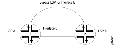
In Figure 1, link protection is enabled on Interface B between Router 1 and Router 2. It is also enabled on LSP A, an LSP that traverses the link between Router 1 and Router 2. If the link between Router 1 and Router 2 fails, traffic from LSP A is quickly switched to the bypass LSP generated by link protection.

Although LSPs traversing an interface can be configured to take advantage of link protection, it is important to note that it is specifically the interface that benefits from link protection. If link protection is enabled on an interface but not on a particular LSP traversing that interface, then if the interface fails, that LSP will also fail.
Link protection does not work on unnumbered interfaces.
Node Protection
Node protection extends the capabilities of link protection. Link protection helps to ensure that traffic going over a specific interface to a neighboring router can continue to reach this router if that interface fails. Node protection ensures that traffic from an LSP traversing a neighboring router can continue to reach its destination even if the neighboring router fails.
When you enable node protection for an LSP, you must also enable link protection. Once enabled, node protection and link protection establish the following types of bypass LSPs:
Next-hop bypass LSP—Provides an alternate route for an LSP to reach a neighboring router. This type of bypass LSP is established when you enable either node protection or link protection.
Next-next-hop bypass LSP—Provides an alternate route for an LSP to get around a neighboring router en route to the destination router. This type of bypass LSP is established exclusively when node protection is configured. If a next-next-hop bypass LSP cannot be created, an attempt is made to signal a next-hop bypass LSP.
In Figure 2, node protection is enabled on Interface B on Router 1. Node protection is also enabled on LSP A, an LSP that traverses the link transiting Router 1, Router 2, and Router 3. If Router 2 suffers a hardware or software failure, traffic from LSP A is switched to the next-next-hop bypass LSP generated by node protection.

The time needed by node protection to switch traffic to a next-next-hop bypass LSP can be significantly longer than the time needed by link protection to switch traffic to a next-hop bypass LSP. Link protection relies on a hardware mechanism to detect a link failure, allowing it to quickly switch traffic to a next-hop bypass LSP.
Node failures are often due to software problems on the node router. Node protection relies on the receipt of hello messages from a neighboring router to determine whether it is still functioning. The time it takes node protection to divert traffic partly depends on how often the node router sends hello messages and how long it takes the node-protected router to react to having not received a hello message. However, once the failure is detected, traffic can be quickly diverted to the next-next-hop bypass LSP.
Node protection provides traffic protection in the event of an error or interruption of the physical link between two routers. It does not provide protection in the event of control plane errors. The following provides an example of a control plane error:
A transit router changes the label of a packet due to a control plane error.
When the ingress router receives the packet, it considers the label change to be a catastrophic event and deletes both the primary LSP and the associated bypass LSP.
LSP Protection Overview
RSVP-TE extensions establish backup label-switched path (LSP) tunnels for local repair of LSP tunnels. These mechanisms enable immediate re-direction of traffic onto backup LSP tunnels, in the event of a failure.
RFC 4090, Fast Reroute Extensions to RSVP-TE for LSP Tunnels, describes two different types of traffic protection for RSVP-signaled LSPs:
One-to-one backup—In this method, detour LSPs for each protected LSP is created at each potential point of local repair.
Facility backup—In this method, a bypass tunnel is created to protect a set of LSPs that have similar backup constraints at a potential failure point, by taking advantage of the MPLS label stacking.
The one-to-one backup and the facility backup methods protect links and nodes during network failure, and can co-exist in a mixed network.
LSP Protection Types Comparison
In the Junos OS, the one-to-one backup of traffic protection is provided by fast reroute. Each LSP requires a protecting LSP to be signaled at each hop except the egress router. This method of LSP protection cannot be shared.
In the facillity backup method, the LSP traffic protection is provided on the node and link. Each LSP requires a protecting LSP to be signaled at each hop except the egress router. Unlike fast reroute, this protecting LSP can be shared by other LSPs.
Table 1 summarizes the traffic protection types.
Table 1: One-to-One Backup Compared with Facility Backup
Comparison | One-to-One Backup | Facility Backup |
|---|---|---|
Name of the protecting LSP | Detour LSP | Bypass LSP |
Sharing of the protecting LSP | Cannot be shared | Can be shared by multiple LSPs |
Junos configuration statements | fast-reroute | node-link-protection and link-protection |
One-to-One Backup Implementation
In the one-to-one backup method, the points of local repair maintain separate backup paths for each LSP passing through a facility. The backup path terminates by merging back with the primary path at a node called the merge point. In this approach, the merge point can be any node downstream from the protected facility.
In the one-to-one backup method, an LSP is established that intersects the original LSP downstream of the point of link or node failure. A separate backup LSP is established for each LSP that is backed up.
One-to-one backup is appropriate under the following circumstances:
Protection of a small number of LSPs relative to the total number of LSPs.
Path selection criteria, such as bandwidth, priority, and link coloring for detour paths is critical.
Control of individual LSPs is important.
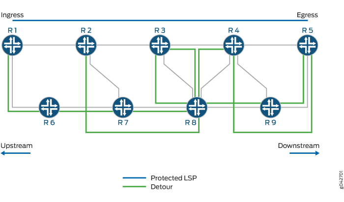
In Figure 3, Routers R1 and R5 are the ingress and egress routers, respectively. A protected LSP is established between the two routers transiting Routers R2, R3, and R4. Router R2 provides user traffic protection by creating a partial backup LSP that merges with the protected LSP at Router R4. This partial one-to-one backup LSP is called a detour. Detours are always calculated to avoid the immediate downstream link and node, providing against both link and node failure.

In the example, the protected LSP is R1-R2-R3-R4-R5, and the following detours are established:
Router R1—R1-R6-R7-R8-R3
Router R2—R2-R7-R8-R4
Router R3—R3-R8-R9-R5
Router R4—R4-R9-R5
To protect an LSP that traverses N nodes fully, there can be as many as (N - 1) detours. The point of local repair sends periodic refresh messages to maintain each backup path, as a result maintaining state information for backup paths protecting individual LSPs is a significant resource burden for the point of local repair. To minimize the number of LSPs in the network, it is desirable to merge a detour back to its protected LSP, when feasible. When a detour LSP intersects its protected LSP at an LSR with the same outgoing interface, it is merged.
Facility Backup Implementation
In the facility backup approach, a point of local repair maintains a single backup path to protect a set of primary LSPs traversing the point of local repair, the facility, and the merge point. The facility backup is based on interface rather than on LSP. While fast reroute protects interfaces or nodes along the entire path of a LSP, the facility backup protection can be applied on interfaces as needed. As a result, fewer states need to be maintained and refreshed which results in a scalable solution. The facility backup method is also called many-to-one backup.
The facility backup method takes advantage of the MPLS label stack. Instead of creating a separate LSP for every backed-up LSP, a single LSP is created that serves to back up a set of LSPs. Such an LSP tunnel is called a bypass tunnel. In this method, a router immediately upstream from a link failure uses an alternate interface to forward traffic to its downstream neighbor, and the merge point should be the node immediately downstream to the facility. This is accomplished by preestablishing a bypass path that is shared by all protected LSPs traversing the failed link. A single bypass path can safeguard a set of protected LSPs. When an outage occurs, the router immediately upstream from the link outage switches protected traffic to the bypass link, then signals the link failure to the ingress router.
The bypass tunnel must intersect the path of the original LSP(s) somewhere downstream of the point of local repair. This constrains the set of LSPs being backed up through that bypass tunnel to those that pass through some common downstream nodes. All LSPs that pass through the point of local repair and through this common node, and that do not also use the facilities involved in the bypass tunnel are candidates for this set of LSPs.
The facility backup method is appropriate in the following situations:
The number of LSPs to be protected is large.
Satisfying path selection criteria (priority, bandwidth, and link coloring) for bypass paths is less critical.
Control at the granularity of individual LSPs is not required.
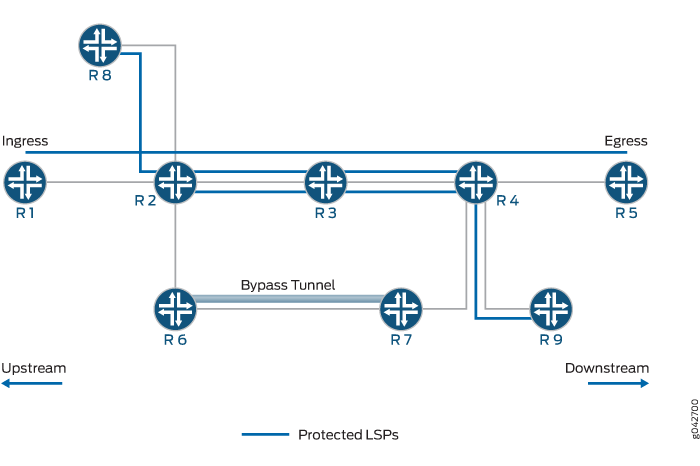
In Figure 4, Routers R1 and R5 are the ingress and egress routers, respectively. Router R2 has established a bypass tunnel that protects against the failure of Router R2-R3 link and Router R3 node. A bypass tunnel is established between Routers R6 and R7. There are three different protected LSPs that are using the same bypass tunnel for protection.

The facility backup method provides a scalability improvement, wherein the same bypass tunnel is also used to protect LSPs from any of RoutersR1, R2, or R8 to any of Routers R4, R5, or R9.
