Multicast Primer
This chapter describes the basics of multicast and explores multicast addressing and the procedures for multicast forwarding using the Physical Interface Module (PIM) and Internet Group Management Protocol (IGMP) protocols. Though the book delves mostly into Layer 2 multicast and the relevant optimizations in EVPN environments, for the sake of completeness this chapter provides background on the multicast technology.
Types of Traffic
There are three types of traffic delivery: unicast, broadcast, and multicast. These different types of traffic forwarding are used for various purposes in computer networks.
Unicast
Unicast traffic is the most predominant. It includes both Layer 2 and Layer 3 unicast. So traffic destined for an IP address, say, 150.1.1.1, will be delivered using hop-by-hop mechanisms. The paths are determined by unicast routing protocols in a Layer 3 network. In a Layer 2 network, the unicast frames are sent to a specific known MAC address.
Broadcast
Broadcast traffic is mainly used in Layer 2 networks. These are packets that are sent to all hosts in the network. Therefore, when a packet is sent to the link-local broadcast address, it is sent to all the hosts in the network. A classic example of broadcast traffic is an ARP packet that is used to determine the IP-to-MAC address mapping of the destination host. Broadcasting packets at Layer 3 is generally avoided because it can potentially flood the Internet.
Multicast
Multicast traffic is forwarded to a group of hosts in a Layer 2 or Layer 3 network and is heavily used in both Layer 2 and Layer 3 networks. In Layer 2 networks, the traffic is sent to those Hosts that are interested in receiving traffic to a particular multicast group. In Layer 3 networks, multicast traffic is steered over different Layer 3 routers to reach the interested listener hosts.
Internet Group Management Protocol (IGMP)
IGMP is a protocol used within a LAN or Layer 3-subnet to express listener interest. Hosts send out IGMP reports to dedicated listeners interested in a particular group. These reports are received by a Layer 3 router. These Layer 3 routers maintain state for this group and forward multicast traffic destined to the group. The Layer 3 routers send out periodic IGMP queries to solicit reports from the hosts. The essence of this book is a paradigm of IGMP snooping enabled at Layer 2 switches for optimized multicast forwarding, and this is covered in detail in later chapters.
Multicast Addressing
Let’s briefly visit the addresses earmarked for multicast applications.
Layer 3 Multicast Addressing
Layer 3 multicast addresses are classified as Class-D addresses and range from 224.0.0.0 to 239.255.255.255. Few multicast addresses among these ranges are reserved for specific purposes, although there are special addresses, 224.0.0/24 for example, that are meant for a specific purpose. This is called the link-local multicast addresses range, and the traffic for these addresses is to be constrained within the subnet. For example, 224.0.0.5 and 224.0.0.13 are used as the destination multicast address for OSPF and PIM to exchange hellos.
The multicast host applications look to join a particular multicast group address, say 235.1.1.1, and expect multicast traffic to be delivered on this address, which they consume. For example, an IPTV host may subscribe for a channel by expressing listener interest for a particular specified group. Also, different channels can be deployed by using different multicast groups.
Layer 2 Multicast Addressing
In the unicast world, a particular L3-IP address maps to a MAC address in Layer 2. In multicast, the particular L3-multicast address is mapped to a L2-multicast address. The L3-multicast address is used in multicast routing, while the L2-multicast address is used in L2-multicast forwarding of the L2-frame.
A host that is interested in a particular group, say 228.11.1.2, expresses its listener interest by sending out an IGMP packet for that group. Also, its hardware programs the L2 MAC address in its hardware corresponding to 228.11.1.2 with, say, MAC address E40B 0102, such that when the multicast traffic arrives with this destination MAC, the host is able to accept the packet. There are certain nuances in the L3-IP to L2-MAC multicast address mapping related to collision, but let’s skip that for now.
Overall, the multicast addresses in Layer 3 and Layer 2 are used by hosts and routers alike to get the multicast traffic signaling and forwarding working.
Protocol Independent Multicast (PIM - ASM)
Let’s review how multicast in Layer 3 networks works, again touching upon only the basic procedures. This background information will be relevant in the chapters in Part 2 that look at the big picture of how multicast is used in data center fabrics.
Any-source multicast (ASM) is a scenario where the listeners or hosts do not know the multicast source information. All they know is the group information for the desired traffic. There is a central device called a rendezvous point (RP) that acts as a liaison between the multicast listeners and the sources for the group.
Typical Multicast Topology
Consider the topology in Figure 1, where there is a multicast source behind R1. R1 is called the first-hop router because it is the first hop to the source. There is also R6, which is called the last-hop router, because it is the last hop from the source and the router nearest to the listener. Typically, the RP is placed centrally in the network. Unicast routing is enabled in the network, and PIM rides on existing unicast routing topology to steer multicast. The unicast reachability can be provided by any of the routing-protocols such as OSPF, ISIS, BGP, or static routing.
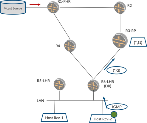
Listener Sends IGMP Report
Figure 1 shows a listener Host-Rcv-2 on the LAN behind R6-LHR. When this host is interested in a particular multicast group, say 235.1.1.1, it sends an IGMP report for this group G.
PIM Hellos and PIM Neighbor Discovery
Before we describe what R6 does with the report, let’s quickly touch upon PIM procedures for neighbor discovery and designated router (DR) election. PIM devices send out PIM hellos to discover each other. In Figure 1, R6 as well as R5 are on the LAN interface. Both R5 and R6 discover each other on the LAN.
If both devices pulled traffic and forwarded it on the LAN, it would result in duplicates. So R5 and R6 enter into a PIM-DR election and the PIM-DR alone creates and propagates state for that subnet. The PIM-NDR may create state but does not propagate it to pull traffic. This DR election is based on a priority field carried in the PIM hello messages. If this is not explicitly carried, the device with the lowest IP address on the interface is elected the PIM-DR.
LHR Creates PIM (*,G) State and Sends PIM Join Towards RP
Let’s resume the path of the Join. In Figure 1, both R5 and R6 receive the IGMP Report and create a PIM (*,G) state. However, R5, being PIM-NDR, does not propagate the state. R6, being the PIM-DR for the LAN, propagates the state by sending a PIM (*,G) Join towards the RP. Since the host and R6 do not know the location of the source(s), R6 looks to send the PIM Join to RP.
Source Sends Multicast Traffic – FHR Sends PIM Register to RP
Let’s go to the next step. Say there is a multicast source that starts sending the multicast traffic. R1, the FHR, sees the multicast traffic from the source. R1 does not have the information of the interested listeners, so it conveys the information about the source to the RP. R1 sends this multicast packet into a unicast tunnel and sends it to the RP. This is called a PIM Register Message and you can see it in Figure 2.
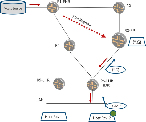
Traffic Flows Over Rendezvous-Point Tree (RPT)
In Figure 2, the RP receives the multicast packet over a unicast tunnel as PIM register packets. The RP decapsulates the multicast traffic and checks if there are any listeners for the group. Since it has a (*,G) Join state created by virtue of the downstream Join from R6, the RP forwards the multicast traffic to R6 over the shared tree. R6 now forwards the traffic over the LAN and the Host-Rcv-2 receives it.
So far so good. But it’s not a good thing that RP receives the multicast traffic over a unicast tunnel. Also, now that R6 has come to know of the multicast source, it can possibly join the multicast source itself and pull the traffic over the shortest path. The two procedures below allow us to move towards this.
RP Joins Source Tree
Now, in Figure 3, R3-RP, having known the location of the source, looks to join the source natively. To achieve this it sends a PIM (S,G) Join towards the source to R2. R2 propagates the (S,G) Join towards R1. Now R1 forwards traffic towards R2, and in turn, R2 towards R3-RP. Then R3-RP informs R1-FHR by sending a PIM Register Stop to stop forwarding traffic on the unicast tunnel. R3-RP forwards the traffic it receives natively to R6-LHR.
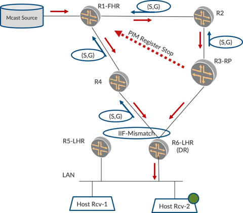
LHR Joins Shortest-Path Tree
At around the same time, R6 realizes the location of the Source and it sends a (S,G) Join towards the Source to R4 to pull traffic over the shortest-path tree (SPT). R4 sends the (S,G) Join to R1. Now, R1 forwards the traffic to R4, and R4 in turns, forwards the traffic to R6. Thus R6 has built a SPT where traffic is forwarded with the least latency.
LHR Switches Traffic From RPT to SPT
Now R6, per Figure 3, receives traffic over both SPT as well as RPT. This is detected by an Incoming Interface Mismatch event that occurs on R6. It should not forward traffic from both trees onto the LAN. It picks the traffic on SPT and forwards it on the LAN.
Also, since the SPT has been formed, it wants to prune the shared tree. Towards this, R6 sends a (*,G) + (S,G, RPT_Prune) message towards RP as shown in Figure 4. This indicates to the RP that the listener is interested in traffic for this group G. However, since it has joined SPT for this particular source S, RP skips forwarding traffic from this source S. If any other source comes alive, say S2, RP forwards the traffic on the shared tree.
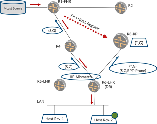
On hearing the S,G,RPT_Prune, RP prunes its (S,G) tree that went over R2 and R1. Also, periodically R1 refreshes the aliveness of the source to the RP by sending NULL registers, therefore the PIM Register message will just have the information that this S, G is alive. No data packets will be sent.
IGMP Leave and PIM Prune
When a host is no longer interested in traffic for group G, it sends out an IGMP Leave for the group. This results in the PIM device, sending out a PIM Prune to cancel out the earlier sent PIM Join.
PIM-ASM Summary
These are the procedures for PIM-ASM.
Phew! Too much detail in too short a time. If this seemed overwhelming, take heart that we will quickly describe PIM-SSM and that should keep things simple. This section on PIM-ASM was included for the sake of providing some relevant background that may be helpful in understanding later chapters. If you don’t fully understand the procedures, you should still be in good shape because this book mainly deals with multicast in Layer 2.
PIM-SSM
We just explored PIM-ASM and its procedures, so now let’s explore PIM-SSM, which is simpler in terms of procedures. In Figure 5 the listener sends an IGMPv3 report. This report has the information on both Group and Source, so R6 can simply send the (S,G) Join towards the source to R4. R4 sends (S,G) towards R1.
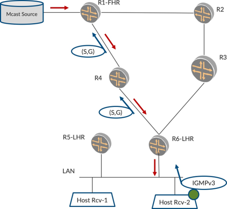
Later, when traffic starts, R1 forwards the traffic towards R4, and R4 in turn forwards traffic towards R6. There is only the source tree. R6 forwards the traffic to listeners on the LAN.
Though PIM-SSM simplifies the procedures in the network, it places the responsibility of the source awareness on the listeners. Since it is very difficult to determine the source information a priori, PIM-ASM is widely deployed because the complexity is handled by the network but the hosts can just express interest in the particular channel or group alone.
This book deals mainly with IGMPv2 hosts. Therefore those hosts send (*,G) Reports rather than IGMPv3 hosts which send (S,G) Reports.
Other Multicast Technologies
What we just described is IGMP and PIM. There are other technologies that transport multicast, over a L3-VPN, for example, and BGP-MVPNs or Rosen MVPNs are used to transport multicast in conjunction with PIM. Also, in the MPLS world, multicast is transported by MLDP or RSVP-TE P2MP tunnels that perform the replication over the MPLS core. The procedures for these are beyond the scope of the book.
Summary
Multicast is increasingly being deployed for large scale applications. The dominant force driving multicast seems to be IPTV applications where the challenges of sending-to-many and increasing bandwidth are being addressed by multicast technologies such as:
Multimedia content delivery systems
Stock-ticker applications in stock exchanges
IPTV for live television distribution and televised company meetings
Bulk File Distribution to deliver operating system images/patches.
This chapter started to cover some ground on multicast procedures. It was by no means comprehensive – multicast as a technology has evolved over two decades and has many nuances. So this chapter was intended to provide the basics and get the reader conversant with terms that appear often later in the book. In EVPN Primer chapter we will conduct a similar exercise on EVPN and provide a quick primer to understand the terms and key topics at a very high level.