EVPN Primer
This chapter discusses the basics of EVPN in a very cursory manner, illustrating the key concepts in order to serve as a foundation for future chapters. Relevant links with detailed explanations of topics you may wish to pursue further are included.
Traditionally, L2-switched environments have been confined to a single site and technologies like VPLS have helped stretch the VLANs in such environments. However, L2-switched environments have major challenges with respect to data plane learning in the MPLS core and are unable to achieve active/active multihoming. VPLS supports only active/standby multihoming. Also, VPLS is a MPLS-only technology.
Ethernet VPN (EVPN) is a standards-based technology that provides virtual multipoint bridged connectivity between different Layer 2 domains over an IP or IP/MPLS backbone network. Like other VPN technologies, such as IP VPN and virtual private LAN service (VPLS), EVPN instances are configured on provider edge (PE) routers to maintain logical service separation between customers. The PE routers connect to customer edge (CE) devices, which can be routers, switches, or hosts.
The PE routers then exchange reachability information using Multiprotocol Border Gateway Protocol (MP-BGP) and encapsulated traffic is forwarded between PE routers. Because elements of the architecture are common with other VPN technologies, you can seamlessly introduce and integrate EVPN into existing service environments.
EVPN became the widely adopted paradigm to stretch the VLANs by virtue of several characteristics including:
Control plane MAC learning using BGP signaling mechanisms
Active/active multihoming with ESIs
MAC-Mass withdrawal
Aliasing of unicast traffic from Ingress
BGP-based policy to fine-tune to different customer requirements and scale
Multitenancy
MAC address mobility
EVPNoMPLS was intended to introduce control plane MAC learning using BGP signaling to exchange the MAC routes. Also, active/active multi-homing was addressed with EVPN with the help of Ethernet Segment Identifiers (ESI). While EVPNoMPLS was targeted for service provider networks, VxLAN was rapidly evolving as a data center technology. To be able to stretch the VLANs in a VxLAN data center cloud, EVPN was a good choice with several other advantages that EVPN brought to the table. EVPNoVXLAN soon became the choice for stretching Layer 2 in enterprise data center fabrics.
Let’s begin by briefly introducing the basic building blocks of a data center fabric.
Building Blocks of EVPNoVXLAN
VLAN/Bridge Domain
A virtual LAN (VLAN) is a broadcast domain that is partitioned and isolated in a network at the data link layer (Layer 2). VLANs work by applying tags to network frames and handling these tags – creating the appearance and functionality of network traffic that is physically on a single network but acts as if it is split between separate networks. VLANs keep network applications separate despite being connected to the same network, and without requiring multiple sets of cabling and devices.
VLANs allow you to group hosts together even if they are not connected to the same switch. Because VLAN membership can be configured through software, this simplifies network design and deployment. Many deployments use VLANs to separate their customers’ private zones from each other. That allows each customer’s servers to be grouped together in a single network segment while being located anywhere in their data center.
VXLAN
Virtual Extensible LAN (VXLAN) is a virtualization technology that addresses the scalability problems associated with large cloud computing deployments. It uses a VLAN-like encapsulation technique to encapsulate Layer 2 Ethernet frames within Layer 4 UDP datagrams, using 4789 as the default IANA-assigned destination UDP port number. VXLAN endpoints that terminate VXLAN tunnels can be virtual or physical switch ports. They are known as VXLAN tunnel endpoints (VTEPs).
VXLAN standardizes as an overlay encapsulation protocol. It increases scalability up to 16 million logical networks and allows for Layer 2 adjacency across IP networks. Multicast or unicast with head-end replication is used to flood broadcast, unknown unicast, and multicast (BUM) traffic.
VXLAN has evolved very well within the industry and has been used as an encapsulation mechanism with EVPN, leading to EVPNoVXLAN procedures.
EVPN VRF (MAC-VRF or EVI)
EVPN is built on a classic VPN model using MP-BGP extensions. The concept of a VRF instance (virtual routing and forwarding) is inherited from the L3VPN/L2VPN world into EVPN; for example, different EVPN instances (EVIs) can be created for different customers and separate routing and forwarding tables will be maintained for each. This is achieved by employing classic route-distinguisher/route-target mechanisms.
EVI Route-Distinguisher and Route-Target
A route distinguisher is an address qualifier unique on an EVPN PE device. It is used to distinguish distinct virtual private network (VPN) routes of separate customers who connect to the provider. Traditionally, the route distinguisher is an 8-octet field prefixed to the customer’s IPv4 address. The resulting 12-octet field is a unique VPN-IPv4 address. The usage of the RD field in EVPN ensures that the MAC/ESI/(S,G) prefixes are unique across the different VRFs in a EVPN device.
The route target is an 8-byte field which is a BGP-extended Communities Attribute. This is utilized to configure the prefixes that are to be suitably imported and exported on the VRFs of the EVPN devices. It helps in keeping the VRF routes constrained within the VRF, such that different customers’ prefixes and traffic do not intersperse with each other.
EVPNoVXLAN
EVPNoVXLAN is the best of both worlds in traditional L3/L2VPNs and the VXLAN paradigm. By combining the two, you can extend VLAN network using VXLAN and also achieve a L2VPN-like segregation using MP-BGP mechanisms for the EVPN family.
Even though VXLAN is an independent technology used to mitigate the scale limitations of VLANs, VXLAN also provides a Layer 3 tunneling paradigm to carry the Layer 2 frames within. This is leveraged with EVPNoVXLAN. That is to say, EVPNoVXLAN is used to stretch the VLANs using VXLAN as the underlay.
MPLS Label Vis-à-vis VXLAN Identifier (VNI)
In classic Layer 3 VPNs using MP-BGP and MPLS, MPLS is the transport. With MP-BGP extensions you carve out services with VRFs. For each VRF, there is a label assigned, called service label, which is used to forward and receive packets within a VRF across the sites.
In EVPNoVXLAN, there is no MPLS. For the transport there are VXLAN and VTEP interface tunnels. To identify a service, (in this case, perhaps a customer-VLAN), you need an identifier to encapsulate and decapsulate the traffic. Towards this, the VNI (VXLAN identifier) segregates the VLANs over the EVPN core.
Sample EVPNoVXLAN Topology
Consider the topology shown in Figure 1 where an EVPNoVXLAN fabric is used to stretch the VLANs spread over several sites. In typical data centers, the VLANs are present in the same geographical site but present in other floors of the same building or in various grouped buildings. The placement of the VLANs over the sites provides a mechanism for managing the network while offering good resilience at scale
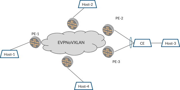
For example, there are several VLANs of different customers behind an EVPN PE, say PE1 to begin with. Over the course of time, there is another site (building/floor, etc.,) behind PE2, where the same VLANs are relevant and there is a need for the VLANs to be stretched. Also, to provide resiliency, PE3 is connected in a multihomed manner such that PE2 and PE3 can coordinate and provide redundancy and resiliency.
The VLANs behind PEs are learned and their information is suitably exchanged with each other. Also, VXLAN tunnels are built using VTEP interfaces such that traffic received on the VLAN by PE1 can be forwarded on the VTEP tunnel to PE2, and PE2 forwards onto the respective VLAN. This tunneling mechanism with VTEP interfaces is provided by the VXLAN underlay, while EVPN service for the VLANs forms the overlay.
Here’s a good overview of EVPNoVXLAN. https://www.juniper.net/documentation/en_US/junos/topics/concept/evpn-vxlan-data-plane-encapsulation.html.
Different VLAN Services with EVPN
EVPN supports three ways to stretch the VLANs over the EVPN core.
EVPN VLAN-based service: This supports the mapping of one routing instance of type EVPN to one VLAN. There is only one bridge table that corresponds to the one VLAN. This type is typically used in EVPNoMPLS service provider networks.
EVPN VLAN-bundle service: Here you have one EVPN instance EVI mapped to a single bridge-domain. This bridge-domain can carry several VLANs ‘bundled’ within it. This is achieved by configuring a VLAN-ID-list or VLAN-range that is to be carried in the bridge-domain. In this scheme, the VLANs are passed through over the EVPN core. This is sometimes called port-based pseudowire (PW) and is used mostly in EVPNoMPLS service provider networks for PW services.
EVPN VLAN-Aware bundle service: With VLAN-Aware bundle service, there is one EVPN instance EVI configured with several bridge-domains. Each of the bridge-domains is mapped to a single VLAN. This way you have each of the VLANs carried with separate VNIs, providing a nice segregation across the VLANs. This scheme is typically used in data center deployments and is used in this book for illustration purposes.
Layer 2 Traffic Types
Layer 2 traffic is broadly divided into unicast, broadcast, unknown unicast, and multicast:
Broadcast traffic is destined to all hosts in the VLAN. This traffic has a specific destination address (0xFFFF) and is flooded onto all the ports by the L2 switch.
Unicast traffic occurs when the destination MAC is unicast MAC and the switch knows the outgoing port for the destination MAC.
Unknown unicast traffic is when the destination MAC is unicast MAC and the switch does not know the outgoing port for the destination MAC. When the switch receives such traffic from a port, it sends out an ARP packet seeking the destination to reply back. This ARP packet has a specific destination MAC address. This packet is flooded onto all ports (excluding the one on which the packet arrived) by making copies for each of the ports.
Multicast traffic has destination MAC addresses in the specified range of multicast addresses. The equivalent IP range for multicast address is Class-D 224.0.0.0 to 239.0.0.0. When the switch receives such a packet, it floods the packet onto all the ports by making one copy for each port. This book deals mainly with the handling of this L2 multicast traffic, the problems with flooding, and the optimizations to mitigate them.
Data-Plane vis-à-vis Control-Plane MAC Learning
Traditional L2-stretched networks with VPLS only support data plane learning as shown in Figure 2. The VPLS PE devices learn of the MAC addresses on the L2-access interfaces. They also learn of the remote MAC addresses that are behind other VPLS PE devices over the pseudowire interfaces. Both of these happen in data plane.
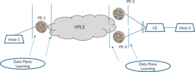
PE-1 learns of the incoming MAC addresses from Host-1 over the L2-access interface while it learns of the incoming MAC addresses from Host-3 over the VPLS pseudowire interface. The data-plane component keeps itself busy with the learning. Typically, several remote PEs and MAC addresses have to be learned from the pseudowires coming from each of them.
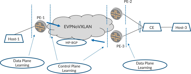
EVPN brings control plane learning to the table, and the MACs that are learned on the access interface are advertised to the other PEs using MP-BGP (EVPN Type 2) routes. In Figure 3, PE-3 advertises EVPN Type 2 routes for the MACs that it learned over the interface towards Host-3. PE-1, upon receiving these Type 2 routes, installs the MAC routes in its forwarding information base, forwarding table (FIB), thus ob- viating the need for MAC learning on the EVPN core interface. Likewise, PE-1advertises EVPN Type 2 routes for the MACs that it learned over the interface to Host-3 which PE-3 programs in its FIB.
EVPN Multihoming with Ethernet Segment Identifier
One of the main features that EVPN brings to networking is active/active multihoming. Historically, with VPLS, there was only single/active multihoming to ensure the classic L2-SPT tree rules are met to avoid loops. With EVPN and its control plane learning feature, this problem is circumvented, and with active/ active multihoming there are these gains:
Unicast Traffic Load Balancing (MAC Aliasing): This ensures that traffic from ingress can be load balanced nicely over two different paths to the multihomed nodes. The traffic load is shared between both the nodes. Also, both the access links towards the CE are utilized.
BUM Traffic Load Sharing: Since both the multihomed nodes and the access links can be utilized, BUM traffic can be load shared, too. However, for a single VLAN, care must be taken that only one node forwards the traffic. This is achieved by designated forwarder (DF) election. When you have several VLANs, the BUM traffic load is nicely shared by the multihomed nodes. This is achieved by one of the multihomed nodes being the DF for some VLANs and the other multihomed node being the DF for the other VLANs.
Resiliency: When one of the multihomed nodes goes down or one of the multihomed links goes down, the unicast/BUM traffic can converge to the other alive node with minimal traffic loss.
All the multihomed-related information is exchanged via BGP routes in the control plane so that the complexity of the redundancy and convergence are moved out of the data plane.
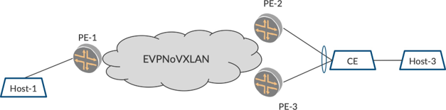
In Figure 4, if PE-2 and PE-3 are to be multihomed, there has to be a construct to suggest the same to the other PEs. This is achieved by binding the two PEs and the multihomed link in a redundancy link pair. This is referred in EVPN as the Ethernet Segment Identifier (ESI).
EVPN Type 1 Route Per ESI
The two PEs, PE-2 and PE-3, are configured with the same ESI value on the multihomed link. When there are several multihomed links, each of the multihomed links are configured with a separate ESI. Thus, we achieve a correlation between the multihomed nodes and the link that they are multihomed.
This ESI information is exchanged separately using EVPN Type 1 routes. The other PEs realize upon receiving the Type 1 route that the two PEs are multihomed on that particular ESI. Also, when the multihomed nodes advertise a MAC route using a Type 2 route, they add the ESI value in the Type 2 route such that the other PEs know that the particular MAC is behind a set of multihomed nodes.
MAC Aliasing
Let’s look at the ingress PE, from PE-1’s point of view. Say there are several MACs behind the CE. These MACs are learned by PE-2 and PE-3 and they are advertised in control plane using EVPN Type 2 MAC Route. Since PE-2 and PE-3 have learned these MACs over the ESI link, these PEs add the ESI value in the Type 2 route.
The ingress PE, when it receives the Type 2 MAC routes realize that these MACs are reachable over both PE-2 and PE-3. This is because PE-2 and PE-3 would have advertised a Type 1 route for the ESI. Once PE1 forms a mapping for the MAC route, it can install the forwarding such that the incoming packets from Host-1 can be load balanced between PE-2 and PE-3. This load balancing usually happens based on the incoming packet’s tuple (source-IP, destination-IP, etc.). Thus, when there are several flows going from Host-1 towards Host-3, these are nicely load balanced between the two paths to the two nodes. This way, both paths, PE-1 to PE-2, and PE-1 to PE-3, are utilized as the traffic processing and forwarding load is shared between PE-2 and PE-3.
MAC Mass Withdrawal with ESI
In addition to helping with MAC aliasing, the paradigm of ESI has one another important benefit. When ESI is configured on a link, be it single-homed or multihomed, it helps in faster convergence. Consider Figure 4. In this case, say the single-homed ingress PE, the PE-1, is configured with an ESI towards Host-1. PE-1 advertises a Type 1 route for that ESI. Also, PE-1 learns and advertises MACs on ESI with Type 2 with the ESI information.
Later, when the link goes down, PE-1 would first withdraw the Type 1 route. Other PEs realize that the ESI behind PE-1 has gone down, and hence would cleanup all the MAC entries learned from the peer. This results in better convergence because once the MAC entries are deleted, ARP can begin and the new MACs can be discovered behind a new PE.
This is a typical use case where a site of MACs is moved from one floor of the building to another. If all these MACs have to be withdrawn individually, it results in service disruption. By virtue of the Type 1 AD route withdrawal, the MACs get cleaned up, BUM flooding begins, and the new PE that the MACs have moved behind is learned quickly.
EVPN Type-4 Route for DF/NDF Calculation
When it comes to BUM forwarding (typically, these are ARP request packets and multicast packets), care should be taken that only one of the multihomed nodes sends the packets to the CE. If both of the nodes for ward the BUM packets to the CE, duplicates would occur and this can cause problems for the hosts.
To have a single forwarder for BUM packets alone, there is a DF election procedure. This is achieved by an EVPN Type 4 route, which carries the ESI information. This Type 4 route for an ESI is used only for electing the DF while the Type 1 route per ESI is used to carry additional information, like Split Horizon Label, etc., for MPLS.
Once the DF election is performed, one of the multihomed nodes becomes the DF and the other multihomed nodes become NDF. The NDF nodes do not forward the BUM traffic that arrives from the core. We will visit further rules related to this in subsequent chapters.
One thing to remember in active/active mode, is that unicast traffic is forwarded by both nodes while BUM traffic is forwarded only by the DF node.
EVPN Type-3 Route for BUM Forwarding
The EVPN peers exchange EVPN Type 3 routes to exchange the VLAN information. This EVPN route is used to build inclusive multicast tunnels between the Ingress and the other EVPN PEs that host the same VLAN. The BUM traffic is forwarded by Ingress using Ingress replication. For example, the Ingress replicates the incoming packet and sends one copy each to the remote PE that hosts the VLAN. Based on the EVPN Type 3 route that is exchanged, the Ingress replication tunnels are built.
Chapter Summary
This chapter provided information on the basic building blocks of EVPN, the Layer 2 types of traffic, and a cursory walk through the different MP-BGP NLRI routes that help in achieving different goals. The benefits of control plane learning were discussed, as well as how multihoming features are achieved using NLRI routes. We touched upon BUM forwarding, of which multicast in particular will be detailed throughout the rest of the book.
This chapter was intended to provide a background of EVPN and is by no means comprehensive. For details on the characteristics and behavior of EVPN, and the differentiators that it brings to the table, it will be best to visit the links provided in the Appendix.
EVPN Primer chapter provides the basic configuration to bring up EVPN in a DC fabric. This includes configuring the underlay and the EVPN overlay, and the VLANs and the ESI information.