Overview
This section provides a collective overview, device positioning, and data packet processing architecture of the QFX Series Switches QFX5220, QFX5230, QFX5240, and QFX5241. In this section, you can also navigate to the device-specific documentation pages by clicking the device name link provided in the introduction.
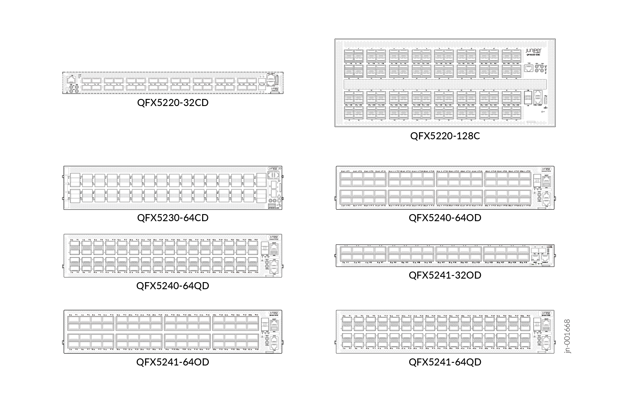
Juniper Networks® QFX5220, QFX5230, QFX5240, and QFX5241 Switches deliver high performance for data center deployments. They support leaf, spine, and super-spine IP fabrics; advanced Layer 2, Layer 3, and MPLS features; low latency (750 ns), and bidirectional throughput of up to 25.6 Tbps. These switches run Junos OS Evolved and provide adaptable port configurations suitable for cloud environments. The switches support capabilities such as EVPN-VXLAN, automation, and energy-efficient power usage per Gbps.
These switches support a range of Ethernet speeds, enabling data centers to integrate updated servers and storage technologies seamlessly, without the need for disruptive redesigns. For more information about the QFX Series Switches, see the Switching section in QFX Series Switches Documentation.
Positioning of QFX5220, QFX5230, QFX5240, and QFX5241 Switches
The key market positioning elements for the QFX5220, QFX5230, QFX5240, and QFX5241 Switches include:
-
Leaf-spine architecture: Optimized for leaf-spine architectures that allow horizontal scaling. This means you can add more leaf or spine switches rather than redesigning the network.
-
Advanced network virtualization and automation: Supports EVPN‑VXLAN, Juniper’s recommended overlay technology for large data center fabric that provides massive scalability, fast convergence, and efficient multitenant isolation.
-
Unified Junos OS experience: Provides a consistent operating model across the fabric that reduces configuration drift and speeds up deployment and troubleshooting.
-
High availability and reliability: Minimizes application response time and avoids latency spikes under load.
Data Packet Processing Architecture
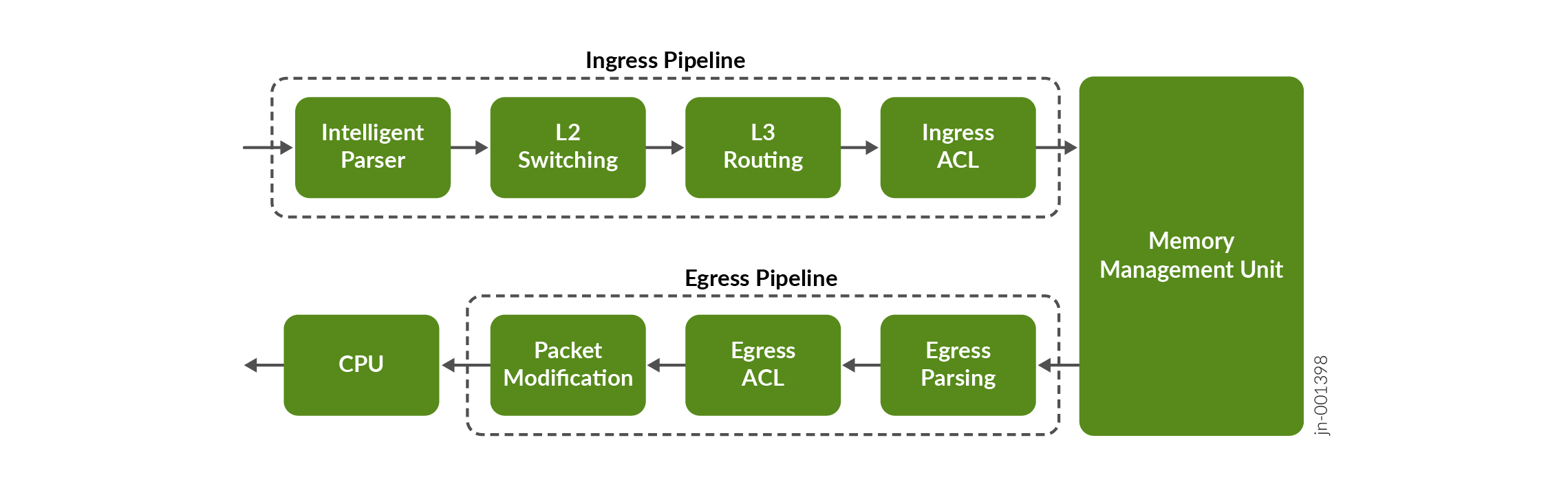
The data packet transit process for all the QFX Series Switches is almost the same. When a data packet enters any QFX Series Switch, it passes through different blocks or levels as shown in Figure 2. At a high level, the data packet transits through three stages: ingress pipeline, memory management unit (MMU), and egress pipeline.
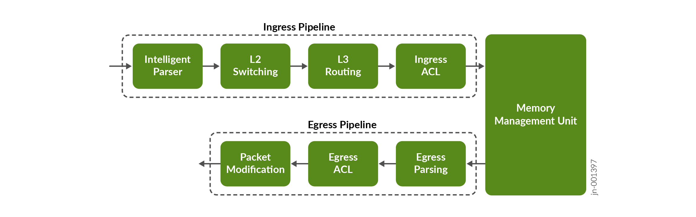
This figure shows that a data packet is processed through a switch’s ingress pipeline, memory management unit, and egress pipeline. The role of each functional block is as follows:
-
The ingress pipeline consists of four blocks: Intelligent Parser, L2 Switching, L3 Routing, and Ingress ACL.
-
The Intelligent Parser analyzes incoming packets, identifies L2 and L3 headers, determines whether the ingress port is VLAN‑enabled or routing‑enabled, and converts parsed information into metadata for downstream processing.
-
The L2 Switching block performs VLAN membership and tagging checks, learns source MAC addresses, and looks up destination MAC addresses. Known unicasts are forwarded to the appropriate egress port, while unknown unicasts are flooded within the VLAN. If the ingress port is not VLAN‑enabled, then the packets bypass this block.
-
The L3 Routing block processes packets received on routing‑enabled ports. It verifies whether the packet is destined for the device and performs routing table lookups. Packets are either forwarded to the destination IP or dropped; flooding is not performed.
-
The Ingress ACL block applies policy actions such as packet filtering, field rewriting, rate limiting, counting, redirection, and security enforcement based on fields parsed earlier.
-
-
The MMU connects the ingress and egress pipelines. Packets written by the ingress pipeline are stored in memory and scheduled—based on priority—by an internal scheduler before being forwarded to the egress pipeline.
-
The egress pipeline consists of the Egress Parser, Egress ACL, and Packet Modification blocks.
-
The Egress Parser block re‑parses packet headers and generates metadata for egress processing.
-
The Egress ACL block applies egress‑side policies using packet header and port information.
-
The Packet Modification block updates fields such as destination MAC addresses and IP header information before transmitting the packet out of the front‑panel port.
-
Non-Transit Data Packet Processing
If a transit packet fails, non-transit packets traverse the three stages in the same way as transit packets, except for one difference, see Figure 3.
When a data packet exits the egress pipeline, it is delivered to the CPU. Before that, during the ingress pipeline, the Intelligent Parser examines the packet to extract the information the CPU needs. If the packet does not contain the required information, the packet is dropped; otherwise, it continues through the egress pipeline to reach the CPU.