ZTIS Configuration and Testing Examples
The following steps describe a sample branch lab setup used to test ZTIS functionality. From a high-level perspective, the configuration performed through the Juniper Mist portal appears the same as in a campus fabric deployment using EVPN-VXLAN, even though the actual configuration generated and applied by the Juniper Mist cloud may differ.
At least two ZTIS-capable access switches are required. In this lab, physical EX4100 switches are used. Each access switch connects to at least two wired clients.
An EX4400 distribution switch connects the two access switches. This switch carries the configured VLANs between the access switches and provides the uplink to the WAN router, where all VLANs are aggregated.
The remaining components can be deployed as virtual machines on a server connected to the physical switches, although physical devices may also be used if available. In this lab setup:
- One virtual Juniper® Session Smart® Router acts as the branch WAN router.
- Four virtual machines simulate wired clients. Each VM connects to an access switch using a dedicated Ethernet port on the server, enabling testing of 802.1X EAP authentication for wired clients.

We will configure and use the following three VLANs in our branch design:
| VLAN name | VLAN ID | WAN router gateway IP | Used for |
|---|---|---|---|
| default | 1 (native) | 10.33.33.1/24 | In-band switch and AP management |
| VLAN1099 | 1099 | 10.99.99.1/24 | VLAN1 for wired and wireless clients |
| VLAN1088 | 1088 | 10.88.88.1/24 | VLAN2 for wired and wireless clients |
Switch Template for This Site
All ZTIS configuration should be performed using a switch template. This approach ensures that the ZTIS configuration on all access switches remains consistently synchronized, particularly for the following items:
- Defining static GBP tag assignments.
- Applying switch policies used for ZTIS enforcement.
Avoid configuring GBP tag assignments or switch policies through overrides, even if the option is available. Maintaining configuration consistency through a switch template is strongly recommended.
Below is the switch template provided in JSON format so it can be easily imported and applied. If you plan to recreate this lab, using the template is the recommended method to minimize errors and prevent misconfigurations.
{
  "additional_config_cmds": [],
  "networks": {
    "VLAN1088": {
      "vlan_id": "1088",
      "subnet": "",
      "subnet6": ""
    },
    "VLAN1099": {
      "vlan_id": "1099",
      "subnet": "",
      "subnet6": ""
    }
  },
  "port_usages": {
    "vlan1099-no-auth": {
      "mode": "access",
      "disabled": false,
      "port_network": "VLAN1099",
      "voip_network": null,
      "stp_edge": false,
      "port_auth": null,
      "allow_multiple_supplicants": null,
      "enable_mac_auth": null,
      "mac_auth_only": null,
      "guest_network": null,
      "bypass_auth_when_server_down": null,
      "dynamic_vlan_networks": null,
      "stp_p2p": false,
      "stp_no_root_port": false,
      "mac_auth_protocol": null,
      "reauth_interval": null,
      "all_networks": false,
      "networks": null,
      "speed": "auto",
      "duplex": "auto",
      "mac_limit": 0,
      "persist_mac": false,
      "poe_disabled": false,
      "enable_qos": false,
      "storm_control": {},
      "mtu": null,
      "description": "",
      "disable_autoneg": false
    },
    "vlan1088-no-auth": {
      "disabled": false,
      "mode": "access",
      "port_network": "VLAN1088",
      "voip_network": null,
      "stp_edge": false,
      "port_auth": null,
      "allow_multiple_supplicants": null,
      "enable_mac_auth": null,
      "mac_auth_only": null,
      "guest_network": null,
      "bypass_auth_when_server_down": null,
      "dynamic_vlan_networks": null,
      "stp_p2p": false,
      "stp_no_root_port": false,
      "mac_auth_protocol": null,
      "reauth_interval": null,
      "all_networks": false,
      "networks": null,
      "speed": "auto",
      "duplex": "auto",
      "mac_limit": 0,
      "persist_mac": false,
      "poe_disabled": false,
      "enable_qos": false,
      "storm_control": {},
      "mtu": null,
      "description": "",
      "disable_autoneg": false
    },
    "vlan1099-eap-auth": {
      "mode": "access",
      "disabled": false,
      "port_network": "VLAN1099",
      "voip_network": null,
      "stp_edge": false,
      "port_auth": "dot1x",
      "allow_multiple_supplicants": false,
      "enable_mac_auth": false,
      "mac_auth_only": false,
      "guest_network": null,
      "bypass_auth_when_server_down": false,
      "dynamic_vlan_networks": null,
      "stp_p2p": false,
      "stp_no_root_port": false,
      "mac_auth_protocol": null,
      "reauth_interval": "65000",
      "all_networks": false,
      "networks": null,
      "speed": "auto",
      "duplex": "auto",
      "mac_limit": 0,
      "persist_mac": false,
      "poe_disabled": false,
      "enable_qos": false,
      "storm_control": {},
      "mtu": null,
      "description": "",
      "disable_autoneg": false
    },
    "dynamic": {
      "mode": "dynamic",
      "reset_default_when": "link_down",
      "rules": []
    },
    "vlan1088-eap-auth": {
      "disabled": false,
      "mode": "access",
      "port_network": "VLAN1088",
      "voip_network": null,
      "stp_edge": false,
      "port_auth": "dot1x",
      "allow_multiple_supplicants": false,
      "enable_mac_auth": false,
      "mac_auth_only": false,
      "guest_network": null,
      "bypass_auth_when_server_down": false,
      "dynamic_vlan_networks": null,
      "stp_p2p": false,
      "stp_no_root_port": false,
      "mac_auth_protocol": null,
      "reauth_interval": "65000",
      "all_networks": false,
      "networks": null,
      "speed": "auto",
      "duplex": "auto",
      "mac_limit": 0,
      "persist_mac": false,
      "poe_disabled": false,
      "enable_qos": false,
      "storm_control": {},
      "mtu": null,
      "description": "",
      "disable_autoneg": false
    },
    "vlan1033-noauth": {
      "disabled": false,
      "mode": "access",
      "port_network": "default",
      "voip_network": null,
      "stp_edge": false,
      "use_vstp": false,
      "port_auth": null,
      "allow_multiple_supplicants": null,
      "enable_mac_auth": null,
      "mac_auth_only": null,
      "guest_network": null,
      "bypass_auth_when_server_down": null,
      "dynamic_vlan_networks": null,
      "stp_p2p": false,
      "stp_no_root_port": false,
      "server_reject_network": null,
      "server_fail_network": null,
      "mac_auth_protocol": null,
      "reauth_interval": null,
      "all_networks": false,
      "networks": null,
      "speed": "auto",
      "duplex": "auto",
      "mac_limit": 0,
      "persist_mac": false,
      "poe_disabled": false,
      "enable_qos": false,
      "storm_control": {},
      "mtu": null,
      "description": "",
      "disable_autoneg": false
    },
    "vlan1088-mab-auth": {
      "disabled": false,
      "mode": "access",
      "port_network": "VLAN1088",
      "voip_network": null,
      "stp_edge": false,
      "port_auth": "dot1x",
      "allow_multiple_supplicants": true,
      "enable_mac_auth": true,
      "mac_auth_only": true,
      "guest_network": null,
      "bypass_auth_when_server_down": false,
      "dynamic_vlan_networks": null,
      "stp_p2p": false,
      "stp_no_root_port": false,
      "mac_auth_protocol": "pap",
      "reauth_interval": "30",
      "all_networks": false,
      "networks": null,
      "speed": "auto",
      "duplex": "auto",
      "mac_limit": 0,
      "persist_mac": false,
      "poe_disabled": false,
      "enable_qos": false,
      "storm_control": {},
      "mtu": null,
      "description": "",
      "disable_autoneg": false,
      "use_vstp": false,
      "server_reject_network": null,
      "server_fail_network": null
    },
    "vlan1099-mab-auth": {
      "mode": "access",
      "disabled": false,
      "port_network": "VLAN1099",
      "voip_network": null,
      "stp_edge": false,
      "port_auth": "dot1x",
      "allow_multiple_supplicants": true,
      "enable_mac_auth": true,
      "mac_auth_only": true,
      "guest_network": null,
      "bypass_auth_when_server_down": false,
      "dynamic_vlan_networks": null,
      "stp_p2p": false,
      "stp_no_root_port": false,
      "mac_auth_protocol": "pap",
      "reauth_interval": "30",
      "all_networks": false,
      "networks": null,
      "speed": "auto",
      "duplex": "auto",
      "mac_limit": 0,
      "persist_mac": false,
      "poe_disabled": false,
      "enable_qos": false,
      "storm_control": {},
      "mtu": null,
      "description": "",
      "disable_autoneg": false,
      "use_vstp": false,
      "server_reject_network": null,
      "server_fail_network": null
    },
    "UAP-LINK": {
      "mode": "trunk",
      "disabled": false,
      "port_network": "default",
      "voip_network": null,
      "stp_edge": false,
      "use_vstp": false,
      "port_auth": null,
      "allow_multiple_supplicants": null,
      "enable_mac_auth": null,
      "mac_auth_only": null,
      "guest_network": null,
      "bypass_auth_when_server_down": null,
      "dynamic_vlan_networks": null,
      "stp_p2p": false,
      "stp_no_root_port": false,
      "server_reject_network": null,
      "server_fail_network": null,
      "mac_auth_protocol": null,
      "reauth_interval": null,
      "all_networks": false,
      "networks": [
        "VLAN1088",
        "VLAN1099"
      ],
      "speed": "auto",
      "duplex": "auto",
      "mac_limit": 0,
      "persist_mac": false,
      "poe_disabled": true,
      "enable_qos": false,
      "storm_control": {},
      "mtu": null,
      "description": "",
      "disable_autoneg": false,
      "stp_disable": false,
      "stp_required": false,
      "mac_auth_preferred": null,
      "bypass_auth_when_server_down_for_unknown_client": null
    },
    "access-point": {
      "mode": "trunk",
      "disabled": false,
      "port_network": "default",
      "voip_network": null,
      "stp_edge": true,
      "port_auth": null,
      "allow_multiple_supplicants": null,
      "enable_mac_auth": null,
      "mac_auth_only": null,
      "guest_network": null,
      "bypass_auth_when_server_down": null,
      "dynamic_vlan_networks": null,
      "stp_p2p": false,
      "stp_no_root_port": false,
      "mac_auth_protocol": null,
      "reauth_interval": null,
      "all_networks": false,
      "networks": [
        "VLAN1088",
        "VLAN1099"
      ],
      "speed": "1g",
      "duplex": "auto",
      "mac_limit": 0,
      "persist_mac": false,
      "poe_disabled": false,
      "enable_qos": false,
      "storm_control": {},
      "mtu": null,
      "description": "",
      "disable_autoneg": true,
      "use_vstp": false,
      "server_reject_network": null,
      "server_fail_network": null,
      "stp_disable": false,
      "stp_required": false,
      "mac_auth_preferred": null,
      "bypass_auth_when_server_down_for_unknown_client": null,
      "poe_legacy_pd": false,
      "poe_priority": null,
      "poe_keep_state_when_reboot": false
    }
  },
  "disabled_system_defined_port_usages": [],
  "extra_routes": {},
  "extra_routes6": {},
  "switch_mgmt": {
    "config_revert_timer": 10,
    "root_password": "",
    "local_accounts": {},
    "protect_re": {
      "enabled": false
    },
    "tacacs": {
      "enabled": false
    },
    "dhcp_option_fqdn": false
  },
  "mist_nac": {
    "enabled": true,
    "auth_servers_timeout": 5,
    "auth_servers_retries": 3,
    "fast_dot1x_timers": false,
    "acct_interim_interval": 0,
    "network": null,
    "coa_enabled": false,
    "coa_port": ""
  },
  "radius_config": {
    "enabled": false,
    "auth_servers": [],
    "acct_servers": [],
    "auth_servers_timeout": 5,
    "auth_servers_retries": 3,
    "fast_dot1x_timers": false,
    "acct_interim_interval": 0,
    "auth_server_selection": "ordered",
    "coa_enabled": false,
    "coa_port": ""
  },
  "vrf_config": {
    "enabled": false
  },
  "remote_syslog": {
    "enabled": false
  },
  "snmp_config": {
    "enabled": false
  },
  "dhcp_snooping": {
    "enabled": false
  },
  "bgp_config": null,
  "routing_policies": {},
  "dns_servers": [
    "8.8.8.8",
    "9.9.9.9"
  ],
  "dns_suffix": [],
  "ntp_servers": [
    "192.168.10.1"
  ],
  "acl_policies": [
    {
      "src_tags": [
        "client1"
      ],
      "actions": [
        {
          "dst_tag": "client1",
          "action": "allow"
        },
        {
          "dst_tag": "client2",
          "action": "allow"
        },
        {
          "dst_tag": "vlan1099",
          "action": "allow"
        },
        {
          "dst_tag": "vlan1088",
          "action": "allow"
        },
        {
          "dst_tag": "branch",
          "action": "allow"
        },
        {
          "dst_tag": "internet",
          "action": "allow"
        }
      ],
      "name": "client1-policy"
    },
    {
      "src_tags": [
        "client2"
      ],
      "actions": [
        {
          "dst_tag": "client1",
          "action": "allow"
        },
        {
          "dst_tag": "client2",
          "action": "allow"
        },
        {
          "dst_tag": "vlan1099",
          "action": "allow"
        },
        {
          "dst_tag": "vlan1088",
          "action": "allow"
        },
        {
          "dst_tag": "branch",
          "action": "allow"
        },
        {
          "dst_tag": "internet",
          "action": "allow"
        }
      ],
      "name": "client2-policy"
    }
  ],
  "port_mirroring": {},
  "acl_tags": {
    "vlan1099": {
      "type": "gbp_resource",
      "subnets": [
        "10.99.99.0/24"
      ],
      "specs": [
        {
          "protocol": "any"
        }
      ]
    },
    "vlan1088": {
      "type": "gbp_resource",
      "subnets": [
        "10.88.88.0/24"
      ],
      "specs": [
        {
          "protocol": "any"
        }
      ]
    },
    "branch": {
      "type": "gbp_resource",
      "subnets": [
        "10.0.0.0/8"
      ],
      "specs": [
        {
          "protocol": "any"
        }
      ]
    },
    "internet": {
      "type": "gbp_resource",
      "subnets": [
        "0.0.0.0/0"
      ],
      "specs": [
        {
          "protocol": "any"
        }
      ]
    },
    "client1": {
      "type": "dynamic_gbp",
      "gbp_tag": 100
    },
    "client2": {
      "type": "dynamic_gbp",
      "gbp_tag": 200
    }
  },
  "name": "uap-branch"
}
If you decide not to import the above JSON, the same configuration can also be created through the Juniper Mist portal as described below for reference. Follow these steps:
Create a new switch template by navigating to Organization -> Switch Templates. Click the Create Template button and create a new template with a unique name. In this example, the template is named “uap-branch”.
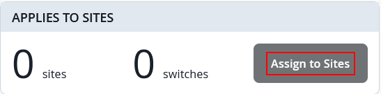
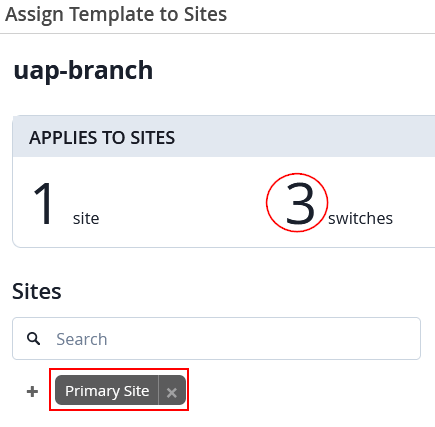
Assign the new template to the site that contains all switches in your branch by selecting the Assign to Sites option. It is important that all switches belong to the same site, so they receive synchronized configurations and share awareness of the same VLANs.
In our case, all three switches are located in Primary Site, hence you should see the configuration below.
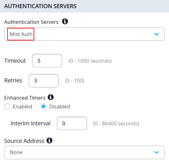
Next, configure the RADIUS server for dynamic authentication. In our case, we used the built-in Juniper Mist NAC solution which just needs the following:
- Authentication Servers=
Mist Auth
But if you have a different RADIUS or NAC solution vendor, apply the individual configuration.
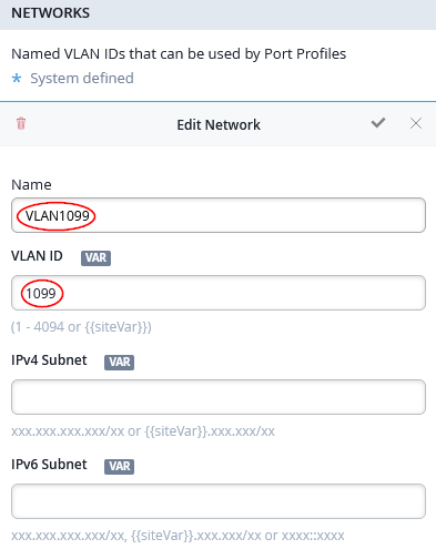
In the next step, we create the individual networks representing our VLANs. With the above table in mind, the following configuration will be made under Networks:
- First Network
- We re-use the existing
defaultnetwork - VLAN ID=
1is the native VLAN ID on all revenue ports. This allows us in-band management of switches and APs in our branch.
- We re-use the existing
- Second Network
- Name=
VLAN1088 - VLAN ID=
1088
- Name=
- Third Network
- Name=
VLAN1099 - VLAN ID=
1099
- Name=
Next, we create the port profiles used in our lab design:
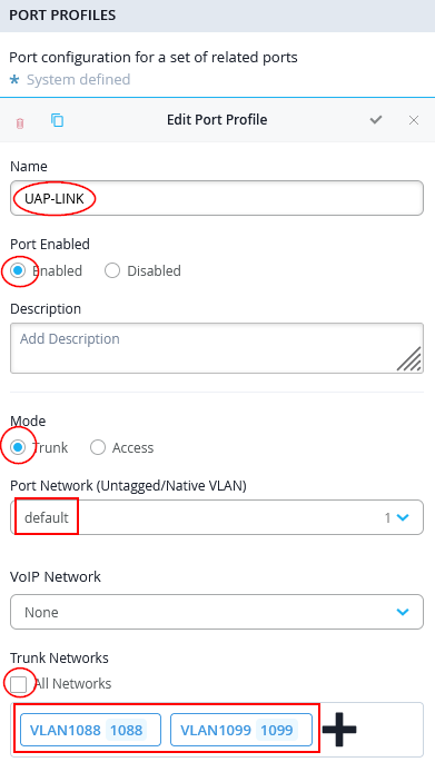
The following port profile is used on our distribution switch only to connect up-link to WAN router with the downlinks to the two access switches:
- Name=
UAP-LINK - Port Enabled=
Enabled - Mode=
Trunk - Port Network=
default - Trunk Networks
- All Networks=
Unchecked/Disabled - Networks=
VLAN1088andVLAN1099
- All Networks=
For the two VLANs used by separate wired clients, we create three port profiles for each:
- A port profile without RADIUS (NAC) dynamic authentication.
This allows initial wired client testing during the lab without
enforcement, helping validate the configuration. It can later also
be used to apply static MAC address or static VLAN GBP tag
assignments for testing. In the template, these profiles end with
-no-auth. - A port profile that uses RADIUS (NAC) dynamic authentication
with MAC address–based client identification. For lab
purposes, the reauthentication interval is reduced to 30 seconds to
avoid waiting up to 10 minutes after configuration changes. This
shortened interval is not recommended for production environments.
In the template, these profiles end with
-mab-auth. - A port profile that uses RADIUS (NAC) dynamic authentication
with 802.1X EAP-TLS for wired clients. EAP-MD5 could also be used
to avoid certificates, but it would not support wireless client
authentication through APs. In the template, these profiles end
with
-eap-auth.
Create the following six port profiles:
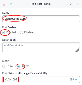
- Port Profile1
- Name=
vlan1099-no-auth - Port Enabled=
Enabled - Mode=
Access - Port Network=
VLAN1099
- Name=
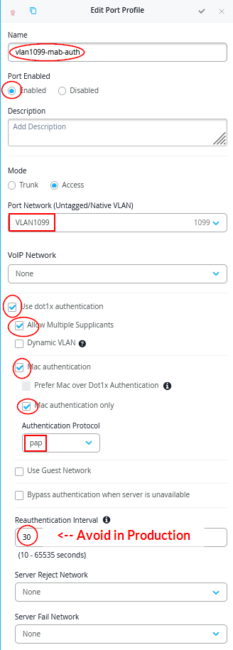
- Port Profile2
- Name=
vlan1099-mab-auth - Port Enabled=
Enabled - Mode=
Access - Port Network=
VLAN1099 - Use dot1x authentication=
Checked/Enabled- Allow Multiple Supplicants=
Checked/Enabled - Mac authentication=
Checked/Enabled- Mac authentication only=
Checked/Enabled - Authentication Protocol=
pap
- Mac authentication only=
- Reauthentication Interval=
30Note: Do not do this in production!
- Allow Multiple Supplicants=
- Name=
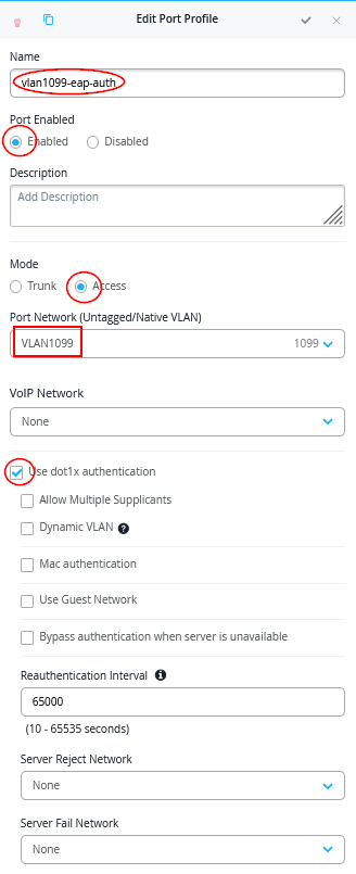
- Port Profile3
- Name=
vlan1099-eap-auth - Port Enabled=
Enabled - Mode=
Access - Port Network=
VLAN1099 - Use dot1x authentication=
Checked/Enabled
- Name=
- Port Profile4
- Name=
vlan1088-no-auth - Port Enabled=
Enabled - Mode=
Access - Port Network=
VLAN1088
- Name=
- Port Profile5
- Name=
vlan1088-mab-auth - Port Enabled=
Enabled - Mode=
Access - Port Network=
VLAN1088 - Use dot1x authentication=
Checked/Enabled- Allow Multiple Supplicants=
Checked/Enabled - Mac authentication=
Checked/Enabled- Mac authentication only=
Checked/Enabled - Authentication Protocol=
pap
- Mac authentication only=
- Reauthentication Interval=
30Note: Do not do in production!
- Allow Multiple Supplicants=
- Name=
- Port Profile6
- Name=
vlan1088-eap-auth - Port Enabled=
Enabled - Mode=
Access - Port Network=
VLAN1088 - Use dot1x authentication=
Checked/Enabled
- Name=
Here are example screenshots:
Port Profile1 example:
Port Profile2 example:
Port Profile3 example:
Save your switch template so that it will be applied to the switches. We’ll apply the ZTIS configuration in a later step.
WAN Router Configuration
You can use any WAN router for this configuration as long as it meets the following requirements:
- Provides Layer 2 to Layer 3 demarcation by acting as the default gateway for all VLANs configured on interfaces connected to the branch distribution and access switches.
- Functions as a DHCP server for all VLANs so that wired and wireless clients—and optionally switches and APs when using in-band management—receive DHCP leases.
- Performs source NAT on the WAN interface so traffic from all VLANs can access the internet using translated addresses.
- Supports one native VLAN while the remaining VLANs are tagged toward downstream switches and APs. This enables in-band device management without requiring a dedicated out-of-band management network in a branch environment.
If you select a Juniper Networks® SRX Series Firewall, its configuration can be managed through the same Juniper Mist portal used for branch switches. An example configuration is provided in the referenced documentation and was also used in this setup.
In our lab, we used a Session Smart Router, and a configuration example is included in this JVD.
Below, we provide the WAN Edge template in JSON format for easy import and deployment.
{
  "type": "standalone",
  "ip_configs": {
    "vlan1033": {
      "type": "static",
      "ip": "10.33.33.1"
    },
    "vlan1088": {
      "type": "static",
      "ip": "10.88.88.1"
    },
    "vlan1099": {
      "type": "static",
      "ip": "10.99.99.1"
    }
  },
  "dhcpd_config": {
    "enabled": true,
    "vlan1033": {
      "type": "local",
      "ip_start": "10.33.33.10",
      "ip_end": "10.33.33.250",
      "gateway": "10.33.33.1",
      "dns_servers": [
        "8.8.8.8",
        "1.1.1.1"
      ],
      "options": {},
      "lease_time": 86400,
      "fixed_bindings": {}
    },
    "vlan1088": {
      "type": "local",
      "ip_start": "10.88.88.10",
      "ip_end": "10.88.88.250",
      "gateway": "10.88.88.1",
      "dns_servers": [
        "8.8.8.8",
        "1.1.1.1"
      ],
      "options": {},
      "lease_time": 86400,
      "fixed_bindings": {}
    },
    "vlan1099": {
      "type": "local",
      "ip_start": "10.99.99.10",
      "ip_end": "10.99.99.250",
      "gateway": "10.99.99.1",
      "dns_servers": [
        "8.8.8.8",
        "1.1.1.1"
      ],
      "options": {},
      "lease_time": 86400,
      "fixed_bindings": {}
    }
  },
  "ospf_areas": {},
  "port_config": {
    "ge-0/0/0": {
      "name": "wan0",
      "usage": "wan",
      "aggregated": false,
      "redundant": false,
      "critical": false,
      "disabled": false,
      "wan_speedtest_mode": "enabled",
      "wan_type": "broadband",
      "ip_config": {
        "type": "dhcp"
      },
      "disable_autoneg": false,
      "wan_source_nat": {
        "disabled": false
      },
      "wan_networks": [],
      "wan_probe_override": {
        "probe_profile": "broadband"
      },
      "vpn_paths": {}
    },
    "ge-0/0/2": {
      "networks": [
        "vlan1088",
        "vlan1033",
        "vlan1099"
      ],
      "usage": "lan",
      "aggregated": false,
      "redundant": false,
      "critical": false,
      "disabled": false
    }
  },
  "bgp_config": {},
  "routing_policies": {},
  "extra_routes": {},
  "path_preferences": {
    "WAN": {
      "strategy": "ordered",
      "paths": [
        {
          "name": "wan0",
          "type": "wan"
        }
      ]
    },
    "LAN": {
      "strategy": "ordered",
      "paths": [
        {
          "type": "local",
          "networks": [
            "vlan1033"
          ]
        },
        {
          "type": "local",
          "networks": [
            "vlan1088"
          ]
        },
        {
          "type": "local",
          "networks": [
            "vlan1099"
          ]
        }
      ]
    }
  },
  "service_policies": [
    {
      "name": "between-branch-vlans",
      "tenants": [
        "vlan1033",
        "vlan1088",
        "vlan1099"
      ],
      "services": [
        "branch"
      ],
      "action": "allow",
      "idp": {
        "enabled": false
      },
      "local_routing": true
    },
    {
      "name": "to-internet",
      "tenants": [
        "vlan1033",
        "vlan1088",
        "vlan1099"
      ],
      "services": [
        "any"
      ],
      "action": "allow",
      "path_preference": "WAN",
      "idp": {
        "enabled": false
      }
    }
  ],
  "gateway_mgmt": {
    "host_out_policies": {},
    "host_in_policies": {},
    "overlay_ip": {}
  },
  "vrf_instances": {},
  "tunnel_configs": {},
  "tunnel_provider_options": {
    "jse": {},
    "zscaler": {},
    "prisma": {}
  },
  "oob_ip_config": {
    "type": "dhcp",
    "node1": {
      "type": "dhcp"
    }
  },
  "ospf_config": {
    "enabled": false,
    "areas": {}
  },
  "remote_syslog": {
    "enabled": false
  },
  "name": "branch-wan-router-ssr"
}
If you are familiar with SRX Series Firewalls and do not use a WAN Edge, we provide a simple Junos configuration that can also be used for this lab below:
root@srx1> show configuration | display set | no-more
set version 23.4R2-S7.4
set system host-name srx1
#set system root-authentication encrypted-password "<use-your-own>"
set system services netconf ssh
set system services ssh root-login allow
set system services ssh protocol-version v2
set system services dhcp-local-server group default  interface ge-0/0/2.1033
set system services dhcp-local-server group VLAN1088 interface ge-0/0/2.1088
set system services dhcp-local-server group VLAN1099 interface ge-0/0/2.1099
set system services dhcp-local-server requested-ip-interface-match
set system name-server 8.8.8.8
set system name-server 1.1.1.1
set system syslog user * any emergency
set system syslog file interactive-commands interactive-commands any
set system syslog file messages any any
set system syslog file messages authorization info
set system license autoupdate url https://ae1.juniper.net/junos/key_retrieval
set security screen ids-option untrust-screen icmp ping-death
set security screen ids-option untrust-screen ip source-route-option
set security screen ids-option untrust-screen ip tear-drop
set security screen ids-option untrust-screen tcp syn-flood alarm-threshold 1024
set security screen ids-option untrust-screen tcp syn-flood attack-threshold 200
set security screen ids-option untrust-screen tcp syn-flood source-threshold 1024
set security screen ids-option untrust-screen tcp syn-flood destination-threshold 2048
set security screen ids-option untrust-screen tcp syn-flood timeout 20
set security screen ids-option untrust-screen tcp land
set security nat source rule-set SNAT from zone trust
set security nat source rule-set SNAT to zone untrust
set security nat source rule-set SNAT rule r1 match source-address 0.0.0.0/0
set security nat source rule-set SNAT rule r1 match destination-address 0.0.0.0/0
set security nat source rule-set SNAT rule r1 then source-nat interface
set security policies from-zone trust to-zone trust policy default-permit match source-address any
set security policies from-zone trust to-zone trust policy default-permit match destination-address any
set security policies from-zone trust to-zone trust policy default-permit match application any
set security policies from-zone trust to-zone trust policy default-permit then permit
set security policies from-zone trust to-zone untrust policy default-permit match source-address any
set security policies from-zone trust to-zone untrust policy default-permit match destination-address any
set security policies from-zone trust to-zone untrust policy default-permit match application any
set security policies from-zone trust to-zone untrust policy default-permit then permit
set security policies from-zone untrust to-zone trust policy default-permit match source-address any
set security policies from-zone untrust to-zone trust policy default-permit match destination-address any
set security policies from-zone untrust to-zone trust policy default-permit match application any
set security policies from-zone untrust to-zone trust policy default-permit then permit
set security policies from-zone untrust to-zone untrust policy default-permit match source-address any
set security policies from-zone untrust to-zone untrust policy default-permit match destination-address any
set security policies from-zone untrust to-zone untrust policy default-permit match application any
set security policies from-zone untrust to-zone untrust policy default-permit then permit
set security zones security-zone untrust screen untrust-screen
set security zones security-zone untrust host-inbound-traffic system-services all
set security zones security-zone untrust host-inbound-traffic protocols all
set security zones security-zone untrust interfaces ge-0/0/0.0
set security zones security-zone trust tcp-rst
set security zones security-zone trust host-inbound-traffic system-services all
set security zones security-zone trust host-inbound-traffic protocols all
set security zones security-zone trust interfaces ge-0/0/2.1099
set security zones security-zone trust interfaces ge-0/0/2.1088
set security zones security-zone trust interfaces ge-0/0/2.1033
set interfaces ge-0/0/0 unit 0 family inet dhcp force-discover
set interfaces ge-0/0/2 flexible-vlan-tagging
set interfaces ge-0/0/2 native-vlan-id 1033
set interfaces ge-0/0/2 unit 1033 vlan-id 1033
set interfaces ge-0/0/2 unit 1033 family inet address 10.33.33.1/24
set interfaces ge-0/0/2 unit 1088 vlan-id 1088
set interfaces ge-0/0/2 unit 1088 family inet address 10.88.88.1/24
set interfaces ge-0/0/2 unit 1099 vlan-id 1099
set interfaces ge-0/0/2 unit 1099 family inet address 10.99.99.1/24
set interfaces fxp0 disable
set interfaces fxp0 unit 0 family inet dhcp force-discover
set access address-assignment pool default  family inet network 10.33.33.0/24
set access address-assignment pool default  family inet range default  low 10.33.33.10
set access address-assignment pool default  family inet range default  high 10.33.33.250
set access address-assignment pool default  family inet dhcp-attributes name-server 8.8.8.8
set access address-assignment pool default  family inet dhcp-attributes name-server 1.1.1.1
set access address-assignment pool default  family inet dhcp-attributes router 10.33.33.1
set access address-assignment pool VLAN1088 family inet network 10.88.88.0/24
set access address-assignment pool VLAN1088 family inet range VLAN1088 low 10.88.88.10
set access address-assignment pool VLAN1088 family inet range VLAN1088 high 10.88.88.250
set access address-assignment pool VLAN1088 family inet dhcp-attributes name-server 8.8.8.8
set access address-assignment pool VLAN1088 family inet dhcp-attributes name-server 1.1.1.1
set access address-assignment pool VLAN1088 family inet dhcp-attributes router 10.88.88.1
set access address-assignment pool VLAN1099 family inet network 10.99.99.0/24
set access address-assignment pool VLAN1099 family inet range VLAN1099 low 10.99.99.10
set access address-assignment pool VLAN1099 family inet range VLAN1099 high 10.99.99.250
set access address-assignment pool VLAN1099 family inet dhcp-attributes name-server 8.8.8.8
set access address-assignment pool VLAN1099 family inet dhcp-attributes name-server 1.1.1.1
set access address-assignment pool VLAN1099 family inet dhcp-attributes router 10.99.99.1
set protocols lldp interface all
set protocols lldp-med interface all
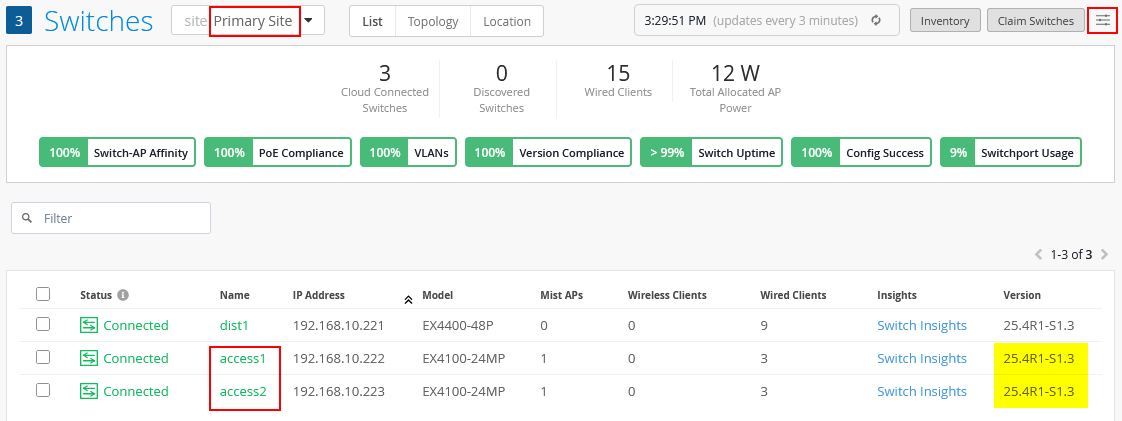
Access and Distribution Switch Configuration
Navigate to Switches and select “Primary Site”. Switch to the “List” view, open the hamburger menu in the upper-right corner, and filter by version. You should see the installed Junos versions on the switches. Verify that your access switches are ZTIS-capable and that the installed Junos firmware supports ZTIS. If not, replace the switches or upgrade the firmware.
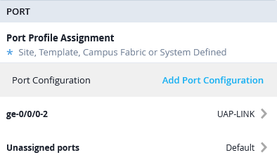
Now, select the Distribution Switch and configure the Ports with the following port profiles:
- Port Profile
- Port IDs=
ge-0/0/0-2 - Interface=
L2 Interface - Configuration Profile=
UAP-Link
- Port IDs=
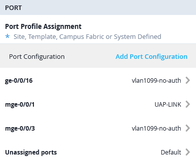
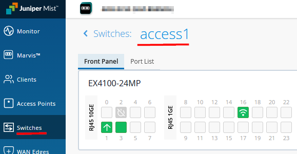
Next, go to Access Switch1 and configure the Ports with the following port profiles:
- Port Profile1
- Port IDs=
mge-0/0/1 - Interface=
L2 Interface - Configuration Profile=
UAP-Link
- Port IDs=
- Port Profile2
- Port IDs=
mge-0/0/3 - Interface=
L2 Interface - Configuration Profile=
vlan1099-no-auth
- Port IDs=
- Port Profile3
- Port IDs=
ge-0/0/16 - Interface=
L2 Interface - Configuration Profile=
vlan1099-no-auth
- Port IDs=
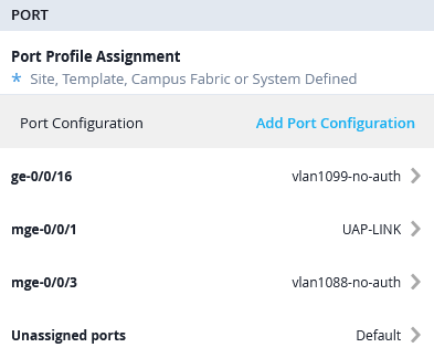
Then, go to Access Switch2 and configure the Ports with the following port profiles:
- Port Profile1
- Port IDs=
mge-0/0/1 - Interface=
L2 Interface - Configuration Profile=
UAP-Link
- Port IDs=
- Port Profile2
- Port IDs=
mge-0/0/3 - Interface=
L2 Interface - Configuration Profile=
vlan1088-no-auth
- Port IDs=
- Port Profile3
- Port IDs=
ge-0/0/16 - Interface=
L2 Interface - Configuration Profile=
vlan1099-no-auth
- Port IDs=
RADIUS (NAC) Configuration
It is strongly recommended to assign GBP tags for ZTIS through
dynamic RADIUS-based authentication using an NAC solution. To
assign a GBP tag within the RADIUS access-accept message, you must
use one of the following Juniper vendor-specific (ID 2636)
attributes. The standard RADIUS attribute Filter-ID
(Type 11) cannot be used.
- You can use the older Juniper RADIUS VSA
Juniper-Switching-Filter(Type 48 as string). With this attribute, the returned value must be a string similar to the following example:apply action gbp-tag 100. - Alternatively, you can use the newer Juniper RADIUS VSA
Juniper-Group-Based-Policy-Id(Type 53 as integer). With this attribute, the returned value is simply the GBP tag number, for example100.
Only one of these attributes can be used to assign a GBP tag at a time. The newer attribute is recommended because it still allows the legacy attribute to be used in the same access-accept message to reference an additional ACL filter if required. If the newer VSA is not supported by the RADIUS server dictionary, you can fall back to the legacy attribute instead. The Auth Policy Labels example below demonstrates how both can be used.
The following section provides an example VSA configuration for a FreeRADIUS server.
# using new VSA for EAP authentication like EAP-MD5 (wired-only), PEAP or EAP-TTLS
PermEmp01 Auth-Type = EAP, Cleartext-Password := "gbp"
Juniper-Group-Based-Policy-Id = "100"
# using new VSA for MAC-based client authentication
001094001199 Cleartext-Password := "001094001199"
Juniper-Group-Based-Policy-Id = "100"
# using old VSA for EAP authentication like EAP-MD5 (wired-only), PEAP or EAP-TTLS
PermEmp01 Auth-Type = EAP, Cleartext-Password := "gbp"
Juniper-Switching-Filter = "apply action gbp-tag 100"
# using old VSA for MAC-based client authentication
001094001199 Cleartext-Password := "001094001199"
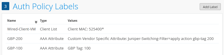
Juniper-Switching-Filter = "apply action gbp-tag 100"Since we use the built-in Juniper NAC solution in our example, we first navigate to Organization -> Auth Policy Labels to configure four example labels:
- Label1 is used to identify wired desktop VMs for MAC
address-based authentication. All those in our environment start
with OUI
0x52:54:00.- Label Name=
Wired-Client-VM - Label Type=
Client List - Label Values=
52:54:00:*
- Label Name=
- Label2 is used to define a return attribute for a successful
client authentication using the new VSA for GBP tag assignment.
- Label Name=
GBP-100 - Label Type=
AAA Attribute - Label Values=
GBP Tag - GBP Tag Values=
100
- Label Name=
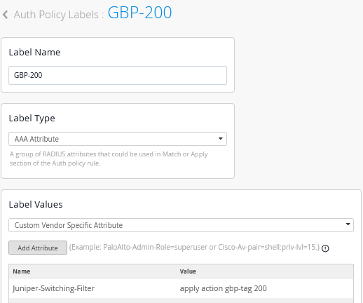
- Label3 is used to define a return attribute for a successful
client authentication using the legacy VSA for GBP tag assignment.
- Label Name=
GBP-200 - Label Type=
AAA Attribute - Label Values=
Custom Vendor Specific Attribute - Attribute1
- Name=
Juniper-Switching-Filter - Value=
apply action gbp-tag 200
- Name=
- Label Name=
The following auth labels should now be defined:
OPTIONAL: In this lab, EAP-TLS is primarily used for wireless client authentication. This assumes that a public key infrastructure (PKI) is available, including an enterprise root certificate authority capable of issuing client certificates. The required setup steps are not repeated here, as they are already documented in a separate JVD that can be followed for guidance here. The examples for client configuration are also covered in a JVD for Windows and Linux clients here.
Keep in mind that you can avoid the complexity of certificate creation and enrollment of wired clients by choosing either EAP-MD5 or MAB for wired clients.
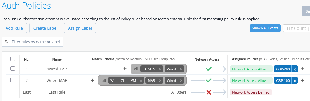
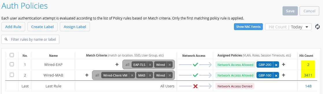
By navigating to Organization -> Auth Policies, we define an initial authentication ruleset as follows:
- Rule1
- Name=
Wired-EAP - Match Criteria=
EAP-TLS AND Wired - Policy=
Pass - Assigned Policies=
Network Access AllowedandGBP-200
- Name=
- Rule2
- Name=
Wired-MAB - Match Criteria=
Wired-Client-VMANDMABANDWired - Policy=
Pass - Assigned Policies=
Network Access AllowedandGBP-100
- Name=
When completed, this configuration should look similar to the example shown below:
Adding ZTIS Configuration
In a production environment, you should schedule a maintenance window when adding GBP policies for the first time.
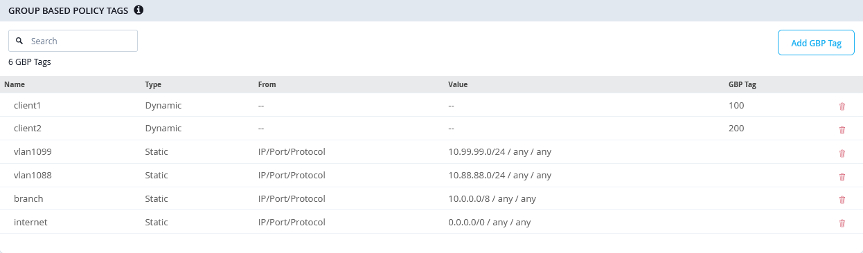
Now that the lab configuration is in place, we can proceed with adding the ZTIS configuration. All ZTIS settings must be applied through a switch template to ensure consistent and synchronized configuration across all access switches within the same site (the branch site in this example). Navigate to Organization -> Switch Templates and select the template created earlier. The first step is to define the GBP tag assignments and destination IP address rules as described below:
- GBP Tag Policy1
- Name=
client1 - Tag assignment=
Dynamic - GBP Tag=
100
- Name=
- GBP Tag Policy2
- Name=
client2 - Tag assignment=
Dynamic - GBP Tag=
200
- Name=
- GBP Tag Policy3
- Name=
vlan1099 - Tag assignment=
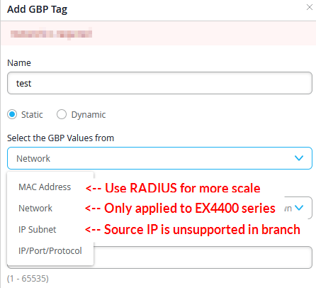
Static - Select the GBP Values from=
IP/Port/Protocol - Destination IP Addresses=
10.99.99.0/24 - Protocol=
Any - Destination Port=
<none> - GBP Tag=
<none>
- Name=
- GBP Tag Policy4
- Name=
vlan1088 - Tag assignment=
Static - Select the GBP Values from=
IP/Port/Protocol - Destination IP Addresses=
10.88.88.0/24 - Protocol=
Any - Destination Port=
<none> - GBP Tag=
<none>
- Name=
- GBP Tag Policy5
- Name=
branch - Tag assignment=
Static - Select the GBP Values from=
IP/Port/Protocol - Destination IP Addresses=
10.0.0.0/8 - Protocol=
Any - Destination Port=
<none> - GBP Tag=
<none>
- Name=
- GBP Tag Policy6
- Name=
internet - Tag assignment=
Static - Select the GBP Values from=
IP/Port/Protocol - Destination IP Addresses=
0.0.0.0/0 - Protocol=
Any - Destination Port=
<none> - GBP Tag=
<none>
- Name=
The resulting configuration should look similar to this:
When using the other static GBP configuration options, keep in mind the following limitations and recommendations:
- Static MAC address GBP tag assignments should be only used when you do not have a RADIUS server deployed. It’s recommended that you use a central RADIUS server for client authentication management as it scales better and you may use client identification based on MAC address OUI vendor IDs.
- Static network assignments (or VLANs) are limited to EX4400 Series only as mentioned above.
- IP subnet refers to the GBP assignment by source IP address which is not supported in branch designs and only possible in campus fabric designs.
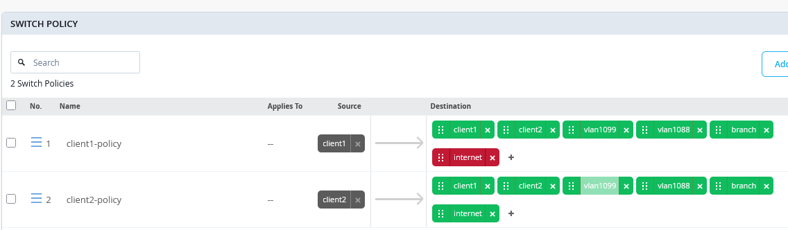
In the next step, create the GBP policies that will be used for enforcement. Follow the previously described guidelines when ordering destination rules:
- All rules that match against a destination GBP tag must appear first in the list. These rules apply only to traffic within the same VLAN, which is a known limitation of ZTIS.
- IP prefix destinations should then be ordered from the longest prefix to the shortest (assuming they do not overlap), ensuring that more specific rules are evaluated before more general ones. A rule covering internet traffic with a /0 prefix should always be placed last for a given GBP source tag. Destination IP prefixes may also be used for traffic within the same VLAN, but they are required for traffic directed toward other VLANs.
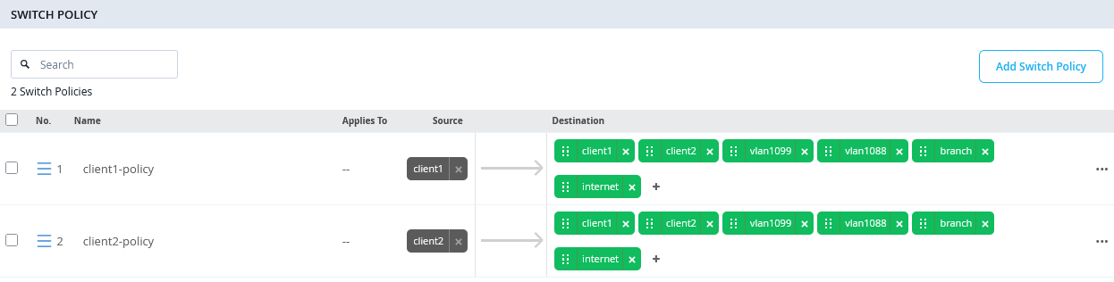
The resulting configuration example looks like the following:
- Switch Policy1
- Name=
client1-policy - Source=
client1 - Destination1
- Destination=
client1(is a destination-gbp tag first in the ruleset) - Traffic=
allow
- Destination=
- Destination2
- Destination=
client2(is a destination-gbp tag first in the ruleset) - Traffic=
allow
- Destination=
- Destination3
- Destination=
vlan1099(is a /24 destination IP-Address second in our ruleset) - Traffic=
allow
- Destination=
- Destination4
- Destination=
vlan1088(is a /24 destination IP-Address second in our ruleset) - Traffic=
allow
- Destination=
- Destination5
- Destination=
branch(is a /8 destination IP-Address third in our ruleset) - Traffic=
allow
- Destination=
- Destination6
- Destination=
internet(is a /0 destination IP-Address always last in the ruleset) - Traffic=
allow
- Destination=
- Name=
- Switch Policy2
- Name=
client2-policy - Source=
client2 - Destination1
- Destination=
client1(is a destination-gbp tag first in the ruleset) - Traffic=
allow
- Destination=
- Destination2
- Destination=
client2(is a destination-gbp tag first in the ruleset) - Traffic=
allow
- Destination=
- Destination3
- Destination=
vlan1099(is a /24 destination IP-Address second in our ruleset) - Traffic=
allow
- Destination=
- Destination4
- Destination=
vlan1088(is a /24 destination IP-Address second in our ruleset) - Traffic=
allow
- Destination=
- Destination5
- Destination=
branch(is a /8 destination IP-Address third in our ruleset) - Traffic=
allow
- Destination=
- Destination6
- Destination=
internet(is a /0 destination IP-Address always last in the ruleset) - Traffic=
allow
- Destination=
- Name=
We do not block any traffic here as we first want to use the monitoring function to review how traffic flows.
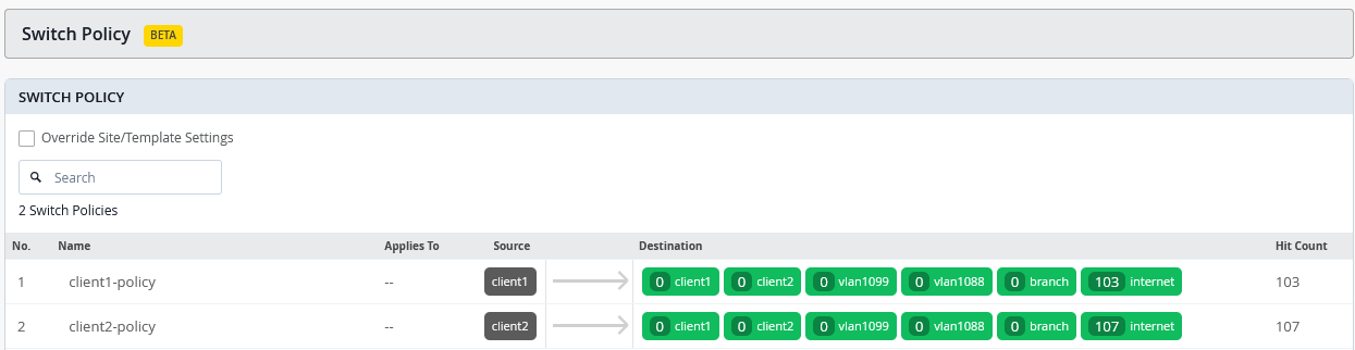
When all configuration is finished, your switch policy should look similar to the following:
When saving the templates, keep in mind that this is the first time GBP policies are being applied. As previously mentioned, the packet forwarding engine on all standalone switches receiving this GBP policy configuration for the first time will restart. If a Virtual Chassis is deployed, you must manually reboot the entire Virtual Chassis to activate the initial GBP configuration.
On your access switches, the resulting Junos configuration will look like the example shown below:
root@access1> show configuration | display set | match gbp
set groups top chassis forwarding-options gbp-pure-l2-profile
set groups top firewall family any filter gbp_client1-policy term 01 from gbp-src-tag 100
set groups top firewall family any filter gbp_client1-policy term 01 from gbp-dst-tag 100
set groups top firewall family any filter gbp_client1-policy term 01 then count gbp_client1-policy_01
set groups top firewall family any filter gbp_client1-policy term 01 then accept
set groups top firewall family any filter gbp_client1-policy term 02 from gbp-src-tag 100
set groups top firewall family any filter gbp_client1-policy term 02 from gbp-dst-tag 200
set groups top firewall family any filter gbp_client1-policy term 02 then count gbp_client1-policy_02
set groups top firewall family any filter gbp_client1-policy term 02 then accept
set groups top firewall family any filter gbp_client1-policy term 03 from ip-version ipv4 ip-destination-address 10.99.99.0/24
set groups top firewall family any filter gbp_client1-policy term 03 from gbp-src-tag 100
set groups top firewall family any filter gbp_client1-policy term 03 then count gbp_client1-policy_03
set groups top firewall family any filter gbp_client1-policy term 03 then accept
set groups top firewall family any filter gbp_client1-policy term 04 from ip-version ipv4 ip-destination-address 10.88.88.0/24
set groups top firewall family any filter gbp_client1-policy term 04 from gbp-src-tag 100
set groups top firewall family any filter gbp_client1-policy term 04 then count gbp_client1-policy_04
set groups top firewall family any filter gbp_client1-policy term 04 then accept
set groups top firewall family any filter gbp_client1-policy term 05 from ip-version ipv4 ip-destination-address 10.0.0.0/8
set groups top firewall family any filter gbp_client1-policy term 05 from gbp-src-tag 100
set groups top firewall family any filter gbp_client1-policy term 05 then count gbp_client1-policy_05
set groups top firewall family any filter gbp_client1-policy term 05 then accept
set groups top firewall family any filter gbp_client1-policy term 06 from ip-version ipv4 ip-destination-address 0.0.0.0/0
set groups top firewall family any filter gbp_client1-policy term 06 from gbp-src-tag 100
set groups top firewall family any filter gbp_client1-policy term 06 then count gbp_client1-policy_06
set groups top firewall family any filter gbp_client1-policy term 06 then accept
set groups top firewall family any filter gbp_client2-policy term 01 from gbp-src-tag 200
set groups top firewall family any filter gbp_client2-policy term 01 from gbp-dst-tag 100
set groups top firewall family any filter gbp_client2-policy term 01 then count gbp_client2-policy_01
set groups top firewall family any filter gbp_client2-policy term 01 then accept
set groups top firewall family any filter gbp_client2-policy term 02 from gbp-src-tag 200
set groups top firewall family any filter gbp_client2-policy term 02 from gbp-dst-tag 200
set groups top firewall family any filter gbp_client2-policy term 02 then count gbp_client2-policy_02
set groups top firewall family any filter gbp_client2-policy term 02 then accept
set groups top firewall family any filter gbp_client2-policy term 03 from ip-version ipv4 ip-destination-address 10.99.99.0/24
set groups top firewall family any filter gbp_client2-policy term 03 from gbp-src-tag 200
set groups top firewall family any filter gbp_client2-policy term 03 then count gbp_client2-policy_03
set groups top firewall family any filter gbp_client2-policy term 03 then accept
set groups top firewall family any filter gbp_client2-policy term 04 from ip-version ipv4 ip-destination-address 10.88.88.0/24
set groups top firewall family any filter gbp_client2-policy term 04 from gbp-src-tag 200
set groups top firewall family any filter gbp_client2-policy term 04 then count gbp_client2-policy_04
set groups top firewall family any filter gbp_client2-policy term 04 then accept
set groups top firewall family any filter gbp_client2-policy term 05 from ip-version ipv4 ip-destination-address 10.0.0.0/8
set groups top firewall family any filter gbp_client2-policy term 05 from gbp-src-tag 200
set groups top firewall family any filter gbp_client2-policy term 05 then count gbp_client2-policy_05
set groups top firewall family any filter gbp_client2-policy term 05 then accept
set groups top firewall family any filter gbp_client2-policy term 06 from ip-version ipv4 ip-destination-address 0.0.0.0/0
set groups top firewall family any filter gbp_client2-policy term 06 from gbp-src-tag 200
set groups top firewall family any filter gbp_client2-policy term 06 then count gbp_client2-policy_06
set groups top firewall family any filter gbp_client2-policy term 06 then accept
In addition to the GBP policies, you will also notice other changes, as the access switch operates like a small, isolated EVPN fabric internally, with policy control based on VXLAN.
mist@access1> show configuration | display set | no-more
.
set groups top chassis forwarding-options gbp-pure-l2-profile
.
# firewall policy ruleset from above
.
set groups top interfaces lo0 unit 0 family inet address 100.100.0.0/32
set groups top routing-options router-id 100.100.0.0
set groups top protocols evpn no-core-isolation
set groups top protocols evpn encapsulation vxlan
set groups top protocols evpn extended-vni-list all
set groups top switch-options vtep-source-interface lo0.0
set groups top switch-options route-distinguisher 100.100.0.0:1
set groups top switch-options vrf-target target:100:100
.
set groups top protocols unified-access-policy mac 5d:5b:35:ff:ff:01
set groups top protocols unified-access-policy key "<secret>"
set protocols unified-access-policy interface mge-0/0/1 inter-switch-link
.
set vlans VLAN1088 vlan-id 1088
set vlans VLAN1088 no-arp-suppression
set vlans VLAN1088 vxlan vni 11088
set vlans VLAN1099 vlan-id 1099
set vlans VLAN1099 no-arp-suppression
set vlans VLAN1099 vxlan vni 11099
set vlans default vlan-id 1
set vlans default l3-interface irb.0
set vlans default no-arp-suppression
set vlans default vxlan vni 10001
Additional Junos CLI on Switches
At the time this documentation was written, the Juniper Mist cloud did have the capability to autodetect and configure links between ZTIS capable Switches. Hence, we help the system and configure these links manually via additional CLI.
As already pointed out above in a branch design there is no need to configure known ports between ZTIS capable switches. The system will then automatically switch to Multicast L2 message propagation instead of L2 Unicast. Configuring the up/downlinks known for ZTIS gains you the advantage of seeing the GBP-Tags already at the distribution switch connecting your access switches.
On the distribution switch of our lab the Mist-Cloud has detected that the Switch is ZTIS capable and pushed ZTIS configuration and through additional Junos CLI in order to complete the setup we just needed to specify the downlinks to the access switches:
# if the distribution switch is ZTIS capable then
# configure the inter-switch-links as downlinks to access switch
set protocols unified-access-policy interface ge-0/0/1 inter-switch-link
set protocols unified-access-policy interface ge-0/0/2 inter-switch-link
On the access switches we needed to configure the ZTIS uplinks as well. In the future, an auto-detection mechanism is planned to avoid this.
# set the inter-switch-links as uplink to distribution switch when they are ZTIS capable
set protocols unified-access-policy interface mge-0/0/1 inter-switch-link
Testing Your ZTIS Design
When running a lab, at the beginning of it one should figure out the MAC addresses of your client VMs (and WAN router) and create a table like the one shown below.
Using native KVM you can use the following commands:
root@aidelab-dc52-srv:~# virsh domiflist desktop1
 Interface   Type     Source     Model    MAC
-------------------------------------------------------------
 vnet7       bridge   br0        virtio   52:54:00:5d:5a:8d
 vnet8       bridge   unusedd1   virtio   52:54:00:1e:bc:30
 vnet9       bridge   desktop1   virtio   52:54:00:79:a7:47
root@aidelab-dc52-srv:~# virsh domiflist desktop2
 Interface   Type     Source     Model    MAC
-------------------------------------------------------------
 vnet10      bridge   br0        virtio   52:54:00:41:ae:ed
 vnet11      bridge   unusedd2   virtio   52:54:00:10:04:ac
 vnet12      bridge   desktop2   virtio   52:54:00:ea:15:ed
root@aidelab-dc52-srv:~# virsh domiflist ssr1
 Interface   Type     Source     Model    MAC
-------------------------------------------------------------
 vnet9       bridge   br0        virtio   52:54:00:bc:8a:b8
 vnet10      bridge   unuseds1   virtio   52:54:00:7e:60:72
 vnet11      bridge   uplink1    virtio   52:54:00:ef:18:36
 vnet12      bridge   unuseds2   virtio   52:54:00:3e:c3:6c
 vnet13      bridge   unuseds3   virtio   52:54:00:b9:ab:b9
 vnet14      bridge   unuseds4   virtio   52:54:00:ab:59:9c
If your desktop VMs are running Linux, you can perform the following steps inside them:
root@desktop1:~# ip a
.
4: ens5: <BROADCAST,MULTICAST,UP,LOWER_UP> mtu 1500 qdisc fq_codel state UP group default qlen 1000
    link/ether 52:54:00:79:a7:47 brd ff:ff:ff:ff:ff:ff
    inet 10.99.99.99/24 brd 10.99.99.255 scope global ens5
       valid_lft forever preferred_lft forever
    inet6 fe80::5054:ff:fee6:3ad7/64 scope link
       valid_lft forever preferred_lft forever
.
# ping wan-router default GW
root@desktop1:~# ping -c3 10.99.99.1
PING 10.99.99.1 (10.99.99.1) 56(84) bytes of data.
64 bytes from 10.99.99.1: icmp_seq=1 ttl=64 time=1.31 ms
64 bytes from 10.99.99.1: icmp_seq=2 ttl=64 time=1.21 ms
64 bytes from 10.99.99.1: icmp_seq=3 ttl=64 time=1.21 ms
.
# review arp-table
root@desktop1:~# ip neighbor show
10.99.99.1 dev ens5 lladdr 52:54:00:ef:18:36 STALE
With that knowledge, you can create the following table:
| VM | MAC Address | IP Address | VLAN | Authentication | GBP Tag | Switch | Port |
|---|---|---|---|---|---|---|---|
| desktop1 | 52:54:00:79:a7:47 | 10.99.99.99/24 | 1099 | MAB | 100 | access1 | mge-0/0/3 |
| desktop2 | 52:54:00:ea:15:ed | 10.88.88.88/24 | 1088 | MAB | 100 | access2 | mge-0/0/3 |
| desktop3 | 52:54:00:c3:53:e1 | DHCP Lease | 1099 | EAP | 200 | access1 | ge-0/0/16 |
| desktop4 | 52:54:00:db:53:a2 | DHCP Lease | 1099 | EAP | 200 | access2 | ge-0/0/16 |
| ssr1 | 52:54:00:ef:18:36 |
10.99.99.1/24 10.88.88.1/24 10.33.33.1/24 |
1099 1088 1 |
access1+2 | mge-0/0/1 |
When beginning a new test exercise, it is recommended to follow these best practices to achieve faster and more consistent results:
- Shut down or stop all wired client virtual machines. This ensures that their MAC addresses age out of the access switches as quickly as possible.
- Apply any required GBP configuration changes in the switch template.
- Make any necessary port configuration changes for wired client authentication on the access switches.
- Verify that previously learned client MAC addresses are no longer present by accessing
the access switches through a remote shell and running the CLI command
show
            ethernet-switching table
. If you do not want to wait for MAC address aging, you can clear the table manually using theclear ethernet-switching tablecommand. - Start the new lab by powering on the client virtual machines.
The example output below demonstrates a clean starting state for a lab, confirming that no client MAC addresses are currently learned:
root@access1> clear ethernet-switching table
.
root@access1> show ethernet-switching table
.
MAC flags (S - static MAC, D - dynamic MAC, L - locally learned, P - Persistent static, C - Control MAC
           SE - statistics enabled, NM - non configured MAC, R - remote PE MAC, O - ovsdb MAC,
           B - Blocked MAC)
.
Ethernet switching table : 6 entries, 6 learned
Routing instance : default-switch
   Vlan                MAC                 MAC       GBP    Logical                SVLBNH/      Active
   name                address             flags     tag    interface              VENH Index   source
   default             52:54:00:ef:18:36   D                mge-0/0/1.0 <- Wan-router ssr
   default             5c:5b:35:f1:6e:c8   D                ge-0/0/16.0 <- local AP
   default             5c:5b:35:f1:6f:00   D                mge-0/0/1.0 <- remote AP
   VLAN1088            52:54:00:ef:18:36   D                mge-0/0/1.0 <- Wan-router ssr
   VLAN1099            52:54:00:ef:18:36   D                mge-0/0/1.0 <- Wan-router ssr
.
Let’s begin the first lab with wired clients in the initial configuration shown on the table above. For simplicity, two wired clients are authenticated using MAC address–based authentication. The two other wired clients will use EAP authentication, so we will use EAP-TLS. To support this setup, the wired port configuration on the access switches needs to be changed as follows:
- Access Switch=
access1- Port Profile Assignment1
- Port ID=
mge-0/0/3 - Configuration Profile=
vlan1099-mab-auth
- Port ID=
- Port Profile Assignment2
- Port ID=
ge-0/0/16 - Configuration Profile=
vlan1099-eap-auth
- Port ID=
- Port Profile Assignment1
- Access Switch=access2
- Port Profile Assignment1
- Port ID=
mge-0/0/3 - Configuration Profile=
vlan1088-mab-auth
- Port ID=
- Port Profile Assignment2
- Port ID=
ge-0/0/16 - Configuration Profile=
vlan1099-eap-auth
- Port ID=
- Port Profile Assignment1
In our lab, the distribution switch does not support ZTIS, so we
should verify whether the reports are accurate by using the CLI
command show unified-access-policy. Note: In a campus
fabric environment, for all non–IP Clos fabrics, inter-switch
links should be configured as LAG ae interfaces and should display
only a single LLDP neighbor, since the uplink distribution switches
share the same source MAC address (this is not related to the
ESI-LAG MAC address).
root@access1> show unified-access-policy
.
Unified Acces Policy Status : Enabled
.
Destination Mac             : 5d:5b:35:ff:ff:01
Source Mac                  : d4:99:6c:d1:2a:0c
Robust Count                : 3
.
Interface          Link-Type               Intf-Status          UAP-LLDP Neighbor Count
ge-0/0/16          Access Point            UP                   0
mge-0/0/1          Inter Switch Link       UP                   0
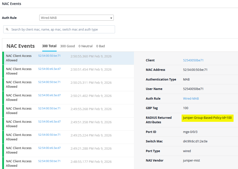
After all your wired and wireless clients are onboarded, review the RADIUS NAC reports under Organization -> Auth Policies.
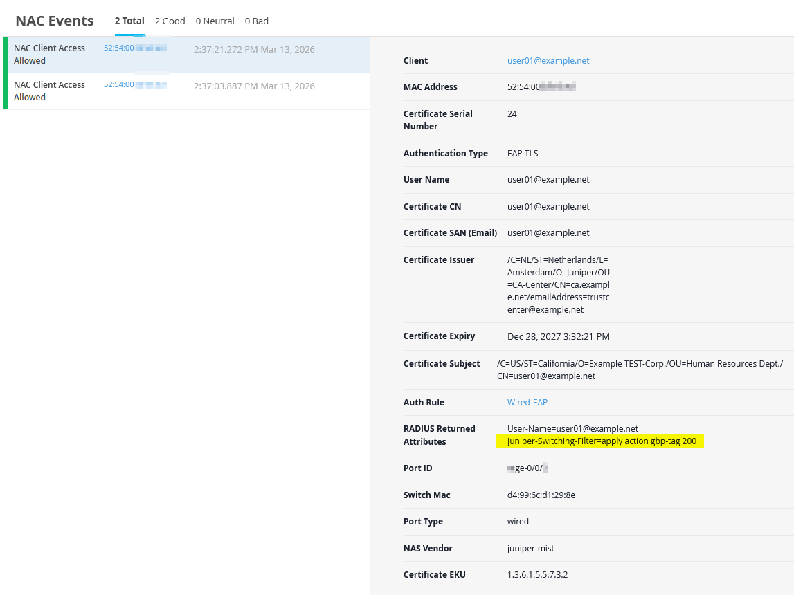
Reviewing the NAC events for wired clients will show the assigned GBP tag value using the new VSA attribute.
Reviewing the NAC events for wired EAP-TLS clients will show the assigned GBP tag value using the old VSA attribute when doing EAP-TLS authentication.
You can review the wired client’s MAB authentication by connecting through remote shell to the switch and using the following CLI commands:
root@access1> show dot1x interface mge-0/0/3.0
802.1X Information:
Interface     Role           State           MAC address          User
mge-0/0/3.0   Authenticator  Authenticated   52:54:00:79:a7:47    525400e63ad7
.
root@access1> show dot1x interface mge-0/0/3.0 detail
mge-0/0/3.0
  Role: Authenticator
  Administrative state: Auto
  Supplicant mode: Multiple
  Number of retries: 3
  Quiet period: 60 seconds
  Transmit period: 30 seconds
  Mac Radius: Enabled
  Mac Radius Restrict: Enabled
  Mac Radius Authentication Protocol: PAP
  Reauthentication: Enabled
  Configured Reauthentication interval: 30 seconds
  Supplicant timeout: 30 seconds
  Server timeout: 30 seconds
  Maximum EAPOL requests: 2
  Guest VLAN member: not configured
  Last Mac-Learn Request: 1c:fd:08:75:c5:4f
  Last Mac-Learn Time: 2026-02-09 15:20:34.518712
  Authentication session limit: 100
  Number of connected supplicants: 1
    Supplicant: 525400e63ad7, 52:54:00:79:a7:47
      Operational state: Authenticated
      Backend Authentication state: Idle
      Authentication method: Mac Radius
      Authentication Mode: Mac-Radius
      Authenticated VLAN: VLAN1099
      Group Based Policy Id: 100
      Session Reauth interval: 30 seconds  <- Do not do this in production
      Reauthentication due in 17 seconds
      Session Accounting Interim  Interval: 600 seconds
      Accounting Update  due in 74 seconds
      Eapol-Block: Not In Effect
      Domain: Data
You can review the wired client’s EAP authentication by connecting through remote shell to the switch and using the following CLI commands:
root@access1> show dot1x interface ge-0/0/16.0
802.1X Information:
Interface     Role           State           MAC address          User
ge-0/0/16.0   Authenticator  Authenticated   52:54:00:C3:53:E1    user01@example.net
.
root@access1> show dot1x interface ge-0/0/16.0 detail
ge-0/0/16.0
  Role: Authenticator
  Administrative state: Auto
  Supplicant mode: Single
  Number of retries: 3
  Quiet period: 60 seconds
  Transmit period: 30 seconds
  Mac Radius: Disabled
  Mac Radius Restrict: Disabled
  Reauthentication: Enabled
  Configured Reauthentication interval: 65000 seconds
  Supplicant timeout: 30 seconds
  Server timeout: 30 seconds
  Maximum EAPOL requests: 2
  Guest VLAN member: not configured
  Last Mac-Learn Request: 52:54:00:bf:e3:ed
  Last Mac-Learn Time: 2026-03-13 13:37:01.521638
  Authentication session limit: 100
  Number of connected supplicants: 1
    Supplicant: user01@example.net, 52:54:00:C3:53:E1
      Operational state: Authenticated
      Backend Authentication state: Idle
      Authentication method: Radius
      Authentication Mode: EAP
      Authenticated VLAN: VLAN1099
      Dynamic Filter: apply action gbp-tag 200
      Group Based Policy Id: 200
      Session Reauth interval: 65000 seconds
      Reauthentication due in 64436 seconds
      Session Accounting Interim  Interval: 600 seconds
      Accounting Update  due in 36 seconds
      Eapol-Block: Not In Effect
      Domain: Data
Now review the Ethernet switching tables on both access switches to confirm which GBP tags are associated with the wired and wireless clients.
On the Access1 switch we see the following:
root@access1> show ethernet-switching table
.
MAC flags (S - static MAC, D - dynamic MAC, L - locally learned, P - Persistent static, C - Control MAC
           SE - statistics enabled, NM - non configured MAC, R - remote PE MAC, O - ovsdb MAC,
           B - Blocked MAC)
.
Ethernet switching table : 13 entries, 13 learned
Routing instance : default-switch
   Vlan                MAC                 MAC       GBP    Logical                SVLBNH/      Active
   name                address             flags     tag    interface              VENH Index   source
   default             52:54:00:ef:18:36   D                mge-0/0/1.0
   default             5c:5b:35:f1:6e:c8   D                ge-0/0/16.0
   default             5c:5b:35:f1:6f:00   D                mge-0/0/1.0
   default             d4:99:6c:d1:2e:3e   D                mge-0/0/1.0
   VLAN1088            52:54:00:ea:15:ed   D          100   mge-0/0/1.0 <- remote desktop2
   VLAN1088            d4:99:6c:d1:2e:3e   D                mge-0/0/1.0
   VLAN1088            d4:99:6c:d1:2e:8c   D                mge-0/0/1.0
   VLAN1099            52:54:00:c3:53:e1   D          200   ge-0/0/16.0 <- local desktop3
                VLAN1099            52:54:00:db:53:a2   D          200   mge-0/0/1.0 <- remote desktop4
                VLAN1099            52:54:00:79:a7:47   D          100   mge-0/0/3.0 <- local desktop1
   VLAN1099            52:54:00:ef:18:36   D                mge-0/0/1.0
   VLAN1099            d4:99:6c:d1:2e:3e   D                mge-0/0/1.0
   VLAN1099            d4:99:6c:d1:2e:8c   D                mge-0/0/1.0
On the Access2 switch we see the following:
root@access2> show ethernet-switching table
.
MAC flags (S - static MAC, D - dynamic MAC, L - locally learned, P - Persistent static, C - Control MAC
           SE - statistics enabled, NM - non configured MAC, R - remote PE MAC, O - ovsdb MAC,
           B - Blocked MAC)
.
Ethernet switching table : 15 entries, 15 learned
Routing instance : default-switch
   Vlan                MAC                 MAC       GBP    Logical                SVLBNH/      Active
   name                address             flags     tag    interface              VENH Index   source
   default             52:54:00:ef:18:36   D                mge-0/0/1.0
   default             5c:5b:35:f1:6e:c8   D                mge-0/0/1.0
   default             5c:5b:35:f1:6f:00   D                ge-0/0/16.0
   default             d4:99:6c:d1:29:be   D                mge-0/0/1.0
   default             d4:99:6c:d1:2a:0c   D                mge-0/0/1.0
   VLAN1088            52:54:00:ea:15:ed   D          100   mge-0/0/3.0 <- local desktop2
   VLAN1088            52:54:00:ef:18:36   D                mge-0/0/1.0
   VLAN1088            d4:99:6c:d1:29:be   D                mge-0/0/1.0
   VLAN1088            d4:99:6c:d1:2a:0c   D                mge-0/0/1.0
   VLAN1099            52:54:00:c3:53:e1   D          200   mge-0/0/1.0 <- remote desktop3
                VLAN1099            52:54:00:db:53:a2   D          200   ge-0/0/16.0 <- local desktop4
                VLAN1099            52:54:00:79:a7:47   D          100   mge-0/0/1.0 <- remote desktop1
   VLAN1099            52:54:00:ef:18:36   D                mge-0/0/1.0
   VLAN1099            d4:99:6c:d1:29:be   D                mge-0/0/1.0
   VLAN1099            d4:99:6c:d1:2a:0c   D                mge-0/0/1.0
This confirms that GBP tags are not only learned locally, as
expected on the local interfaces mge-0/0/3 and
ge-0/0/16 but are also learned through remote device.
We can observe and verify the following:
- A wired MAB client GBP tag learned from a remote access switch
appears through the distribution switch interface
mge-0/0/1. - A wired EAP client GBP tag from a remotely connected access
switch is learned through the distribution switch interface
mge-0/0/1.
For the next phase of evaluation, we will use the desktop1 VM along with the firewall counters local to each switch to validate the configured policies. You will also notice this behavior when reviewing the following individual switch configuration:
When scrolling down the page, you see counters for the rules you configured.
However, these rule counters are intended for long-term monitoring and update approximately every three minutes. For lab testing where immediate results are needed, use a remote shell to an access switch and check the counters locally. Before running a test, it is recommended to clear the counters first.
root@access1> clear firewall all
.
root@access1> show firewall
.
Filter: gbp_client1-policy
Counters:
Name                                                                            Bytes              Packets
gbp_client1-policy_01                                                               0                    0
gbp_client1-policy_02                                                               0                    0
gbp_client1-policy_03                                                               0                    0
gbp_client1-policy_04                                                               0                    0
gbp_client1-policy_05                                                               0                    0
gbp_client1-policy_06                                                               0                    0
.
Filter: gbp_client2-policy
Counters:
Name                                                                            Bytes              Packets
gbp_client2-policy_01                                                               0                    0
gbp_client2-policy_02                                                               0                    0
gbp_client2-policy_03                                                               0                    0
gbp_client2-policy_04                                                               0                    0
gbp_client2-policy_05                                                               0                    0
gbp_client2-policy_06                                                               0                    0
TEST1: Now let’s use the Desktop1 VM (using MAB) to ping our two wired EAP clients that happen to be in the same VLAN but have a different GBP tag assigned.
root@desktop1:~# ping -c3 10.99.99.50
PING 10.99.99.50 (10.99.99.50) 56(84) bytes of data.
64 bytes from 10.99.99.50: icmp_seq=1 ttl=64 time=102 ms
64 bytes from 10.99.99.50: icmp_seq=2 ttl=64 time=586 ms
64 bytes from 10.99.99.50: icmp_seq=3 ttl=64 time=46.6 ms
.
root@desktop1:~# ping -c3 10.99.99.51
PING 10.99.99.51 (10.99.99.51) 56(84) bytes of data.
64 bytes from 10.99.99.51: icmp_seq=1 ttl=64 time=8.41 ms
64 bytes from 10.99.99.51: icmp_seq=2 ttl=64 time=78.8 ms
64 bytes from 10.99.99.51: icmp_seq=3 ttl=64 time=192 ms
.
root@desktop1:~# ip neighbor show
10.99.99.51 dev ens5 lladdr 52:54:00:c3:53:e1 REACHABLE
10.99.99.50 dev ens5 lladdr 52:54:00:db:53:a2 REACHABLE
10.99.99.1 dev ens5 lladdr 52:54:00:ef:18:36 STALE
When reviewing the firewall counters on the Access1 switch, you will observe activity corresponding to this bidirectional traffic:
-
gbp_client1-policy_02is used as it is created for source GBP tag 100 to destination GBP tag 200 containing the ICMP request packets. -
gbp_client2-policy_01is used as it is created for source GBP tag 200 to destination GBP tag 100 containing the ICMP reply packets.root@access1> show firewall . Filter: gbp_client1-policy Counters: Name Bytes Packets gbp_client1-policy_01 0 0 gbp_client1-policy_02 876 10 gbp_client1-policy_03 0 0 gbp_client1-policy_04 0 0 gbp_client1-policy_05 0 0 gbp_client1-policy_06 0 0 . Filter: gbp_client2-policy Counters: Name Bytes Packets gbp_client2-policy_01 960 11 gbp_client2-policy_02 0 0 gbp_client2-policy_03 0 0 gbp_client2-policy_04 0 0 gbp_client2-policy_05 0 0 gbp_client2-policy_06 0 0
TEST2: Reset the firewall counters again and then ping the WAN router gateway IP from the Desktop1 VM.
root@desktop1:~# ping -c7 10.99.99.1
PING 10.99.99.1 (10.99.99.1) 56(84) bytes of data.
64 bytes from 10.99.99.1: icmp_seq=1 ttl=64 time=1.59 ms
64 bytes from 10.99.99.1: icmp_seq=2 ttl=64 time=1.37 ms
64 bytes from 10.99.99.1: icmp_seq=3 ttl=64 time=1.50 ms
64 bytes from 10.99.99.1: icmp_seq=4 ttl=64 time=1.19 ms
64 bytes from 10.99.99.1: icmp_seq=5 ttl=64 time=1.59 ms
64 bytes from 10.99.99.1: icmp_seq=6 ttl=64 time=1.18 ms
64 bytes from 10.99.99.1: icmp_seq=7 ttl=64 time=1.45 ms
When reviewing the firewall counters on the Access1 switch, you will observe the following:
- The
gbp_client1-policy_03is applied because it was created for source GBP tag 100 with a destination IP prefix of 10.99.99.0/24. In this case, that prefix represents both the client’s VLAN and the WAN router. This enables the creation of rules for clients within the same VLAN, where defining or assigning GBP tags is not possible.root@access1> show firewall Filter: gbp_client1-policy Counters: Name Bytes Packets gbp_client1-policy_01 0 0 gbp_client1-policy_02 0 0 gbp_client1-policy_03 714 7 gbp_client1-policy_04 0 0 gbp_client1-policy_05 0 0 gbp_client1-policy_06 0 0
TEST3: Reset the firewall counters on the Access1 and Access2 switches and then ping the Desktop2 VM (located at Access2 in vlan1088) from Desktop1 VM (located at Access1 in vlan1099).
root@desktop1:~# ping -c7 10.88.88.88
PING 10.88.88.88 (10.88.88.88) 56(84) bytes of data.
64 bytes from 10.88.88.88: icmp_seq=1 ttl=63 time=2.01 ms
64 bytes from 10.88.88.88: icmp_seq=2 ttl=63 time=2.02 ms
64 bytes from 10.88.88.88: icmp_seq=3 ttl=63 time=1.98 ms
64 bytes from 10.88.88.88: icmp_seq=4 ttl=63 time=2.33 ms
64 bytes from 10.88.88.88: icmp_seq=5 ttl=63 time=2.29 ms
64 bytes from 10.88.88.88: icmp_seq=6 ttl=63 time=2.26 ms
64 bytes from 10.88.88.88: icmp_seq=7 ttl=63 time=2.20 ms
When reviewing the Access1 switch counters you will see output like the following:
root@access1> show firewall
.
Filter: gbp_client1-policy
Counters:
Name                                                                            Bytes              Packets
gbp_client1-policy_01                                                               0                    0
gbp_client1-policy_02                                                               0                    0
gbp_client1-policy_03                                                               0                    0
gbp_client1-policy_04                                                             714                    7
gbp_client1-policy_05                                                               0                    0
gbp_client1-policy_06                                                               0                    0
When reviewing the Access2 switch counters you will see output like the following:
root@access2> show firewall
Filter: gbp_client1-policy
Counters:
Name                                                                            Bytes              Packets
gbp_client1-policy_01                                                               0                    0
gbp_client1-policy_02                                                               0                    0
gbp_client1-policy_03                                                             714                    7
gbp_client1-policy_04                                                               0                    0
gbp_client1-policy_05                                                               0                    0
gbp_client1-policy_06                                                               0                    0
This is because the bidirectional traffic uses the following flows:
- On the Access1 switch the ICMP request uses
gbp_client1-policy_04for source GBP tag 100 destined to the IP prefix of 10.88.88.0/24 which is the VLAN in which the Desktop2 VM is located. - On the Access2 switch the ICMP reply uses
gbp_client1-policy_03for source GBP tag 100 destined to the IP prefix of 10.99.99.0/24 which is the VLAN in which the Desktop1 VM is located.
TEST4: Reset the firewall counters again and then ping the switches in vlan1033 for in-band management from the Desktop1 VM.
root@desktop1:~# ping -c3 10.33.33.10
PING 10.33.33.10 (10.33.33.10) 56(84) bytes of data.
64 bytes from 10.33.33.10: icmp_seq=1 ttl=63 time=2.35 ms
64 bytes from 10.33.33.10: icmp_seq=2 ttl=63 time=2.25 ms
64 bytes from 10.33.33.10: icmp_seq=3 ttl=63 time=2.15 ms
.
root@desktop1:~# ping -c3 10.33.33.11
PING 10.33.33.11 (10.33.33.11) 56(84) bytes of data.
64 bytes from 10.33.33.11: icmp_seq=1 ttl=63 time=2.35 ms
64 bytes from 10.33.33.11: icmp_seq=2 ttl=63 time=2.01 ms
64 bytes from 10.33.33.11: icmp_seq=3 ttl=63 time=2.26 ms
When reviewing the firewall counters on the Access1 switch, you will observe the following:
-
gbp_client1-policy_05is applied because it was created for source GBP tag 100 destined to the IP prefix of 10.0.0.0/8. In this case, it is used to control traffic within the same branch when multiple VLANs are present, serving as a general catch-all rule for traffic that has not been explicitly defined by more specific policies.root@access1> show firewall . Filter: gbp_client1-policy Counters: Name Bytes Packets gbp_client1-policy_01 0 0 gbp_client1-policy_02 0 0 gbp_client1-policy_03 0 0 gbp_client1-policy_04 0 0 gbp_client1-policy_05 612 6 gbp_client1-policy_06 0 0
TEST5: Reset the firewall counters again and then from the Desktop1 VM, create traffic towards the internet such as downloading a web page.
root@desktop1:~# wget www.google.com
--2026-02-09 17:18:02--  http://www.google.com/
Resolving www.google.com (www.google.com)... 142.250.189.228, 2607:f8b0:4005:80e::2004
Connecting to www.google.com (www.google.com)|142.250.189.228|:80... connected.
HTTP request sent, awaiting response... 200 OK
Length: unspecified [text/html]
Saving to: ‘index.html’
index.html              [ <=>                ]  17.14K  --.-KB/s    in 0s
2026-02-09 17:18:02 (167 MB/s) - ‘index.html’ saved [17550]
When reviewing the firewall counters on the Access1 switch, you will observe the following:
-
gbp_client1-policy_06is applied because it was created for source GBP tag 100 destined to the IP prefix of 0.0.0.0/0. This rule is intended for all non-local fabric traffic destined for the internet and serves as the final rule to be evaluated.root@access1> show firewall . Filter: gbp_client1-policy Counters: Name Bytes Packets gbp_client1-policy_01 0 0 gbp_client1-policy_02 0 0 gbp_client1-policy_03 0 0 gbp_client1-policy_04 0 0 gbp_client1-policy_05 0 0 gbp_client1-policy_06 709 8
Now that you understand the rules that have been configured and when they are applied, you can begin using them to control or block traffic as needed.
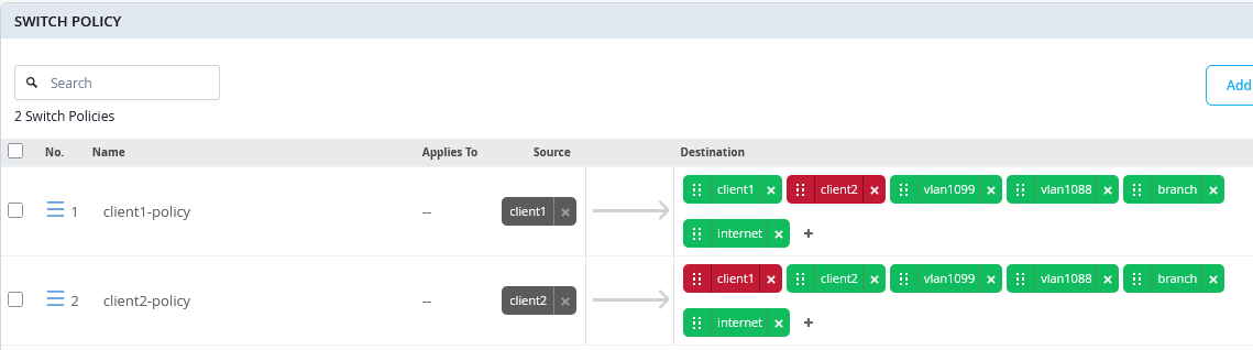
TEST6: Let’s repeat the last lab but this
time block the traffic towards the internet. Go to the switch
template and right-click on internet and select
“deny”.
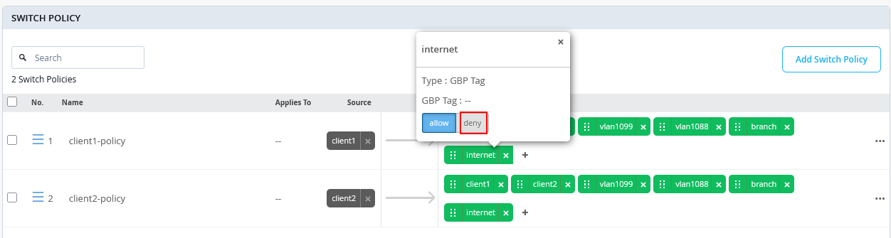
The rule color will change to red. Lastly, save the template so that it is applied to the access switches.
After the configuration has changed, the traffic is no longer allowed:
root@access1> show configuration | display set | match "gbp_client1-policy term 06"
set groups top firewall family any filter gbp_client1-policy term 06 from ip-version ipv4 ip-destination-address 0.0.0.0/0
set groups top firewall family any filter gbp_client1-policy term 06 from gbp-src-tag 100
set groups top firewall family any filter gbp_client1-policy term 06 then count gbp_client1-policy_06
set groups top firewall family any filter gbp_client1-policy term 06 then discard
Reset the firewall counters again and then from the Desktop1 VM, create traffic towards the internet such as downloading a web page. The traffic now fails since we’ve changed the configuration to block it.
root@desktop1:~# wget www.google.com
--2026-02-09 17:38:07--  http://www.google.com/
Resolving www.google.com (www.google.com)... failed: Temporary failure in name resolution.
wget: unable to resolve host address ‘www.google.com’
When reviewing the firewall counters, you will see packet counts for traffic attempts, allowing you to monitor when a client with GBP source tag 100 tries to access internet traffic.
root@access1> show firewall
.
Filter: gbp_client1-policy
Counters:
Name                                                                            Bytes              Packets
gbp_client1-policy_01                                                               0                    0
gbp_client1-policy_02                                                               0                    0
gbp_client1-policy_03                                                               0                    0
gbp_client1-policy_04                                                               0                    0
gbp_client1-policy_05                                                               0                    0
gbp_client1-policy_06                                                            1570                   19
TEST7: To block traffic between wireless and wired clients which are in the same VLAN, review the bidirectional policies matched by TEST1 and block them as shown below.
From the Desktop1 VM, ping the wireless clients in the same VLAN.
root@desktop1:~# ping -c3 10.99.99.50
PING 10.99.99.50 (10.99.99.50) 56(84) bytes of data.
--- 10.99.99.50 ping statistics ---
3 packets transmitted, 0 received, 100% packet loss, time 2031ms
root@desktop1:~# ping -c3 10.99.99.51
PING 10.99.99.51 (10.99.99.51) 56(84) bytes of data.
--- 10.99.99.51 ping statistics ---
3 packets transmitted, 0 received, 100% packet loss, time 2051ms
.
root@desktop1:~# ip neighbor show
10.99.99.51 dev ens5  FAILED
10.99.99.50 dev ens5  FAILED
10.99.99.1 dev ens5 lladdr 52:54:00:ef:18:36 STALE
The firewall counters on the Access1 switch only increment on
the matching rule gbp_client1-policy_02 for the ICMP
requests:
root@access1> show firewall
.
Filter: gbp_client1-policy
Counters:
Name                                                                            Bytes              Packets
gbp_client1-policy_01                                                               0                    0
gbp_client1-policy_02                                                             996                   12
gbp_client1-policy_03                                                               0                    0
gbp_client1-policy_04                                                               0                    0
gbp_client1-policy_05                                                               0                    0
gbp_client1-policy_06                                                               0                    0
.
Filter: gbp_client2-policy
Counters:
Name                                                                            Bytes              Packets
gbp_client2-policy_01                                                               0                    0
gbp_client2-policy_02                                                               0                    0
gbp_client2-policy_03                                                               0                    0
gbp_client2-policy_04                                                               0                    0
gbp_client2-policy_05                                                               0                    0
gbp_client2-policy_06                                                               0                    0