Optional Configurations: DHCP Relay and Multicast
Use these examples to configure optional DHCP relay and multicast forwarding on your collapsed spine data center architecture.
Configure DHCP Relay (Optional)
Requirements
DHCP server.
The devices that you configured in How to Configure a Collapsed Spine with EVPN Multihoming.
Overview
Use this section to configure the spine switches to relay the
DHCP requests to the DHCP server. Enable DHCP relay in a routing instance
with the forward-only option. The forward-only option ensures that DHCP packets are forwarded on the switch but
that no DHCP server client bindings are created.
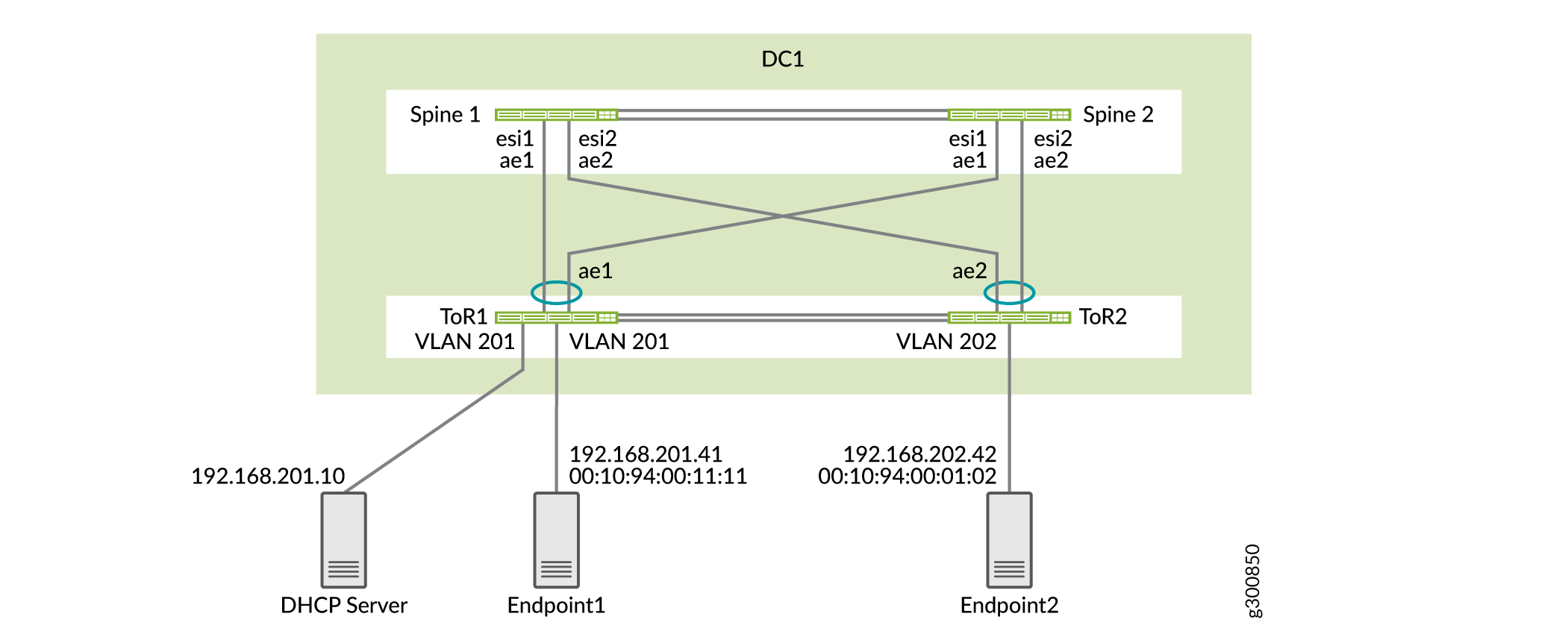
Topology
The DHCP server can be located anywhere in the data center or in a different data center. In this case, the DHCP server is connected to one of the ToR switches in DC1 and the IP address of the DHCP server is 192.168.201.10. The DHCP relay topology is shown in Figure 1.
Configuration
Configure Spine 1
Step-by-Step Procedure
Configure the DHCP relay on the first routing instance.
set routing-instances JNPR_1_VRF forwarding-options dhcp-relay forward-only
set routing-instances JNPR_1_VRF forwarding-options dhcp-relay server-group Server_Group1 192.168.201.10
set routing-instances JNPR_1_VRF forwarding-options dhcp-relay group Relay_Group1 active-server-group Server_Group1
set routing-instances JNPR_1_VRF forwarding-options dhcp-relay group Relay_Group1 route-suppression destination
set routing-instances JNPR_1_VRF forwarding-options dhcp-relay group Relay_Group1 interface irb.201
set routing-instances JNPR_1_VRF forwarding-options dhcp-relay group Relay_Group1 interface irb.202
set routing-instances JNPR_1_VRF forwarding-options dhcp-relay group Relay_Group1 interface irb.203
Configure the DHCP relay on the second routing instance.
set routing-instances JNPR_2_VRF forwarding-options dhcp-relay forward-only
set routing-instances JNPR_2_VRF forwarding-options dhcp-relay server-group Server_Group1 192.168.201.10
set routing-instances JNPR_2_VRF forwarding-options dhcp-relay group Relay_Group1 active-server-group Server_Group1
set routing-instances JNPR_2_VRF forwarding-options dhcp-relay group Relay_Group1 route-suppression destination
set routing-instances JNPR_2_VRF forwarding-options dhcp-relay group Relay_Group1 interface irb.211
set routing-instances JNPR_2_VRF forwarding-options dhcp-relay group Relay_Group1 interface irb.212
set routing-instances JNPR_2_VRF forwarding-options dhcp-relay group Relay_Group1 interface irb.213
Verify the DHCP relay on Spine 1.
user@spine1> show dhcp relay statistics routing-instance JNPR_1_VRF
Packets dropped:
    Total                      50741
    Invalid server address     0
    dhcp-service total         50738

Messages received:
    BOOTREQUEST                3
    DHCPDECLINE                0
    DHCPDISCOVER               1
    DHCPINFORM                 0
    DHCPRELEASE                0
    DHCPREQUEST                2
    DHCPLEASEACTIVE            0
    DHCPLEASEUNASSIGNED        0
    DHCPLEASEUNKNOWN           0
    DHCPLEASEQUERYDONE         0

Messages sent:
    BOOTREPLY                  2
    DHCPOFFER                  0
    DHCPACK                    2
    DHCPNAK                    0
    DHCPFORCERENEW             0
    DHCPLEASEQUERY             0
    DHCPBULKLEASEQUERY         0
Configure Spine 2
Step-by-Step Procedure
Configure the DHCP relay on the first routing instance.
set routing-instances JNPR_1_VRF forwarding-options dhcp-relay forward-only
set routing-instances JNPR_1_VRF forwarding-options dhcp-relay forward-only-replies
set routing-instances JNPR_1_VRF forwarding-options dhcp-relay server-group Server_Group1 192.168.201.10
set routing-instances JNPR_1_VRF forwarding-options dhcp-relay group Relay_Group1 active-server-group Server_Group1
set routing-instances JNPR_1_VRF forwarding-options dhcp-relay group Relay_Group1 route-suppression destination
set routing-instances JNPR_1_VRF forwarding-options dhcp-relay group Relay_Group1 interface irb.201
set routing-instances JNPR_1_VRF forwarding-options dhcp-relay group Relay_Group1 interface irb.202
set routing-instances JNPR_1_VRF forwarding-options dhcp-relay group Relay_Group1 interface irb.203
Configure the DHCP relay on the second routing instance.
set routing-instances JNPR_2_VRF forwarding-options dhcp-relay forward-only
set routing-instances JNPR_2_VRF forwarding-options dhcp-relay forward-only-replies
set routing-instances JNPR_2_VRF forwarding-options dhcp-relay server-group Server_Group1 192.168.201.10
set routing-instances JNPR_2_VRF forwarding-options dhcp-relay group Relay_Group1 active-server-group Server_Group1
set routing-instances JNPR_2_VRF forwarding-options dhcp-relay group Relay_Group1 route-suppression destination
set routing-instances JNPR_2_VRF forwarding-options dhcp-relay group Relay_Group1 interface irb.211
set routing-instances JNPR_2_VRF forwarding-options dhcp-relay group Relay_Group1 interface irb.212
set routing-instances JNPR_2_VRF forwarding-options dhcp-relay group Relay_Group1 interface irb.213
Verify the DHCP relay on Spine 2.
user@spine2> show dhcp relay statistics routing-instance JNPR_1_VRF
Packets dropped:
    Total                      50741
    Invalid server address     0
    dhcp-service total         50738

Messages received:
    BOOTREQUEST                3
    DHCPDECLINE                0
    DHCPDISCOVER               1
    DHCPINFORM                 0
    DHCPRELEASE                0
    DHCPREQUEST                2
    DHCPLEASEACTIVE            0
    DHCPLEASEUNASSIGNED        0
    DHCPLEASEUNKNOWN           0
    DHCPLEASEQUERYDONE         0

Messages sent:
    BOOTREPLY                  2
    DHCPOFFER                  0
    DHCPACK                    2
    DHCPNAK                    0
    DHCPFORCERENEW             0
    DHCPLEASEQUERY             0
    DHCPBULKLEASEQUERY         0
Configure Multicast for Intra-VNI Traffic (Optional)
Requirements
The devices that you configured in How to Configure a Collapsed Spine with EVPN Multihoming.
Overview
Use this section to configure your collapsed spine architecture to allow intra-VNI multicast traffic. The multicast source and receivers are part of the same VLAN.
The collapsed spine architecture with QFX5120 spine switches does not support inter-VNI multicast traffic.
Topology
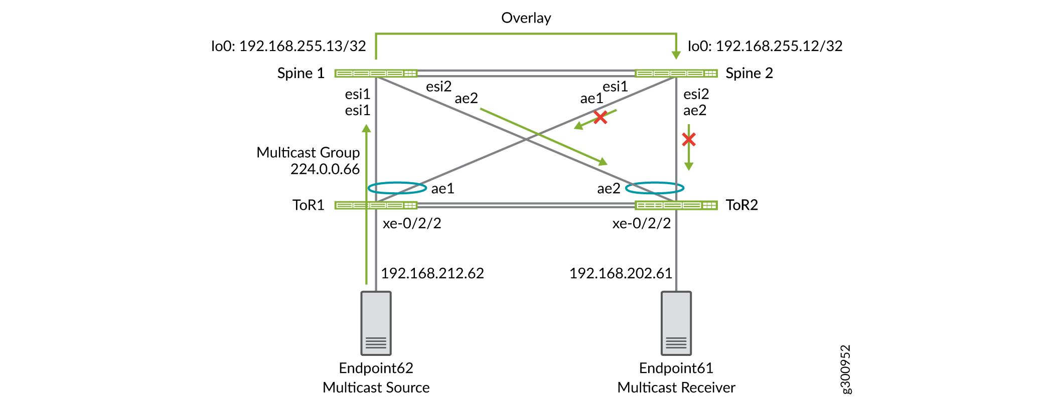
This section includes the configuration for two multicast groups. The first is multicast group 224.0.0.66. As shown in Figure 2, the multicast source is Endpoint 62. The multicast receiver, Endpoint 61, is connected to ToR 2. Both the source and receiver are in the same VLAN, so traffic between them is intra-VNI multicast traffic.
Configuration
- Configure Devices
- Verification for Multicast Group 224.0.0.66
- Verification for Multicast Group 224.0.0.65
Configure Devices
Step-by-Step Procedure
Enable IGMP snooping for all VLANs on both spine switches.
set protocols igmp-snooping vlan VLAN-201 immediate-leave
set protocols igmp-snooping vlan VLAN-202 immediate-leave
set protocols igmp-snooping vlan VLAN-211 immediate-leave
set protocols igmp-snooping vlan VLAN-212 immediate-leave
Configure the ToR switches with IGMP snooping for all VLANs.
set protocols igmp-snooping vlan VLAN-201 immediate-leave
set protocols igmp-snooping vlan VLAN-201 interface ae1.0 multicast-router-interface
set protocols igmp-snooping vlan VLAN-202 immediate-leave
set protocols igmp-snooping vlan VLAN-202 interface ae1.0 multicast-router-interface
set protocols igmp-snooping vlan VLAN-211 immediate-leave
set protocols igmp-snooping vlan VLAN-211 interface ae1.0 multicast-router-interface
set protocols igmp-snooping vlan VLAN-212 immediate-leave
set protocols igmp-snooping vlan VLAN-212 interface ae1.0 multicast-router-interface
Verification for Multicast Group 224.0.0.66
Step-by-Step Procedure
Verify IGMP snooping membership on ToR 2.
user@tor2> show igmp snooping membership
Instance: default-switch

Vlan: VLAN-201

Learning-Domain: default
Interface: ae1.0, Groups: 0

Vlan: VLAN-202

Learning-Domain: default
Interface: ae1.0, Groups: 0

Learning-Domain: default
Interface: xe-0/2/2.0, Groups: 1
    Group: 225.0.0.66
        Group mode: Exclude
        Source: 0.0.0.0
        Last reported by: 192.168.202.61
        Group timeout:     177 Type: Dynamic

Vlan: VLAN-211

Learning-Domain: default
Interface: ae1.0, Groups: 0

Vlan: VLAN-212

Learning-Domain: default
Interface: ae1.0, Groups: 0
Verify IGMP snooping membership on Spine 1.
user@spine1> show igmp snooping evpn membership detail
Instance: default-switch

Vlan: VLAN-201, EVPN-Core-NH: 524301

Learning-Domain: default
Interface: ae2.0, Groups: 0
Interface: ae1.0, Groups: 0

Vlan: VLAN-202, EVPN-Core-NH: 524303

Learning-Domain: default
Interface: ae2.0, Groups: 1
    Group: 225.0.0.66
        Group mode: Exclude
        Source: 0.0.0.0
        Type: Local
Interface: ae1.0, Groups: 0

Vlan: VLAN-211, EVPN-Core-NH: 524307

Learning-Domain: default
Interface: ae2.0, Groups: 0
Interface: ae1.0, Groups: 0

Vlan: VLAN-212, EVPN-Core-NH: 524298

Learning-Domain: default
Interface: ae2.0, Groups: 0
Interface: ae1.0, Groups: 0
Verify IGMP snooping membership on Spine 2.
user@spine2> show igmp snooping evpn membership detail
Instance: default-switch

Vlan: VLAN-201, EVPN-Core-NH: 524298

Learning-Domain: default
Interface: ae2.0, Groups: 0
Interface: ae1.0, Groups: 0

Vlan: VLAN-202, EVPN-Core-NH: 524300

Learning-Domain: default
Interface: ae2.0, Groups: 1
    Group: 225.0.0.66
        Group mode: Exclude
        Source: 0.0.0.0
        Type: Remote
Interface: ae1.0, Groups: 0

Vlan: VLAN-211, EVPN-Core-NH: 524304

Learning-Domain: default
Interface: ae2.0, Groups: 0
Interface: ae1.0, Groups: 0

Vlan: VLAN-212, EVPN-Core-NH: 524306

Learning-Domain: default
Interface: ae2.0, Groups: 0
Interface: ae1.0, Groups: 0
Verify the designated forwarder on Spine 1. The output shows that Spine 1 is the designated forwarder for all Ethernet segments.
user@spine1> show evpn instance designated-forwarder
Instance: default-switch
  Number of ethernet segments: 12
    ESI: 00:00:00:00:00:00:00:00:01:01
      Designated forwarder: 192.168.255.13
    ESI: 00:00:00:00:00:00:00:00:01:02
      Designated forwarder: 192.168.255.13
    ESI: 00:00:00:00:00:00:00:00:01:11
      Designated forwarder: 192.168.255.13
    ESI: 00:00:00:00:00:00:00:00:01:12
      Designated forwarder: 192.168.255.13
Verify the multicast traffic flow on Spine 1.
Based on LAG hashing, ToR 1 sends the multicast traffic to Spine 1. The traffic reaches Spine 1 on the AE1 interface. Spine 1 forwards this traffic through AE2 based on IGMP group membership.
user@spine1> monitor interface traffic detail
Interface    Link  Input packets        (pps)     Output packets        (pps)
ae1           Up     6742041146    (2946565)             3924          (1)
ae2           Up           2536          (0)       6741411465    (2948357)
Verify the multicast traffic flow on Spine 2.
Based on LAG hashing, ToR 1 does not send the multicast traffic to Spine 2. Spine 2 receives this traffic from Spine 1 through the overlay, but it drops this traffic and does not forward it to AE2.
user@spine2> monitor interface traffic detail
Interface    Link  Input packets        (pps)     Output packets        (pps)
ae1           Up           2547          (0)             3762          (1)
ae2           Up           2462          (0)             3769          (1)
Verification for Multicast Group 224.0.0.65
Step-by-Step Procedure
Verify the designated forwarder on Spine 1. The output shows that Spine 1 is still the designated forwarder for all the Ethernet segments.
user@spine1> show evpn instance designated-forwarder
Instance: default-switch
  Number of ethernet segments: 12
    ESI: 00:00:00:00:00:00:00:00:01:01
      Designated forwarder: 192.168.255.13
    ESI: 00:00:00:00:00:00:00:00:01:02
      Designated forwarder: 192.168.255.13
    ESI: 00:00:00:00:00:00:00:00:01:11
      Designated forwarder: 192.168.255.13
    ESI: 00:00:00:00:00:00:00:00:01:12
      Designated forwarder: 192.168.255.13
Verify the multicast traffic flow on Spine 1.
Based on LAG hashing, ToR 1 does not send the multicast traffic to Spine 1, so there is no incoming traffic for this multicast group on Spine 1. Spine 1 receives the multicast stream from Spine 2 through the overlay. Spine 1 drops the traffic and does not forward it to AE2 because Spine 1 and Spine 2 are part of the same Ethernet segments for AE1 and AE2.
user@spine1> monitor interface traffic detail
Interface    Link  Input packets        (pps)     Output packets        (pps)
et-0/0/51     Up           4750    (2947862)             4741          (3)
ae1           Up           1027          (1)             1543          (1)
ae2           Up            991          (0)             1537          (1)
Verify the multicast traffic flow on Spine 2.
Based on LAG hashing, ToR 1 sends the multicast traffic to Spine 2. Spine 2 is not the designated forwarder for the Ethernet segments, but Spine 2 still forwards this traffic to receivers on AE2 based on the local bias rules for multicast forwarding. See Overview of Selective Multicast Forwarding for more information about the EVPN multicast forwarding rules.
user@spine2> monitor interface traffic detail
Interface    Link  Input packets        (pps)     Output packets        (pps)
et-0/0/51     Up           4603          (3)       3458201844    (2948641)
ae1           Up     2985999842    (2948821)             1542          (1)
ae2           Up           1009          (0)       2986000009    (2947024)
You have successfully configured multicast traffic forwarding on your network.