Use Case and Reference Architecture
In this chapter, we describe an example of SD-WAN implementation in a typical hub-and-spoke scenario that leverages different transport technologies to show how it is implemented. A similar lab was built to test this JVD which you can see in the test report.
Keep the following design goals in mind:
- Design for a hub-and-spoke scenario from day one on. Mesh designs always have scale limitations and are not usually friendly to cheap broadband Internet and LTE connections.
- Ensure your hubs have the right connectivity so that the spokes
can reach them using the transport network.
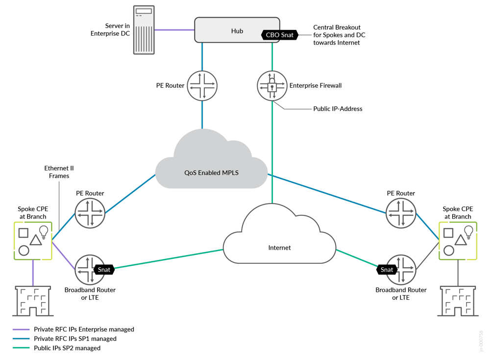
- If you have an MPLS network, your service provider usually provides a routed private IP address to you, or the end-customers manage their own private IP address range (VPLS).
- When the device has any broadband or LTE connection, you can assume that there is a kind of source NAT applied on the path or the IP addresses on the local router are not permanent. In this case, the hub must have a statically assigned public IP address that is reachable from the spoke trying to make a secure vector routing (SVR) connection.
- Local country regulations should not filter or restrict communication on destination UDP port 1280. Because these ports must be at least open for spokes and hubs to establish secure vector routing for the overlay network.
- Consider allowing only VPN traffic inside your SD-WAN to lower the overall traffic. All traffic to services outside your VPN should use local breakout at the spoke.
- Use Session Smart Routers for their secure vector routing (SVR) capability, specifically the adaptive-encryption feature. This feature identifies HTTPS traffic that is already encrypted and avoids re-encrypting it for VPN transmission, conserving processing resources. As a result, the more VPN traffic that is already encrypted, the fewer resources need to be provisioned.
A lab that simulates the real world, having two underlay paths, each with different behavior:
- You can emulate an MPLS path (without the MPLS framing in-between) with private IP addresses that are visible end-to-end. In a real-world environment, those private IP addresses are managed and distributed by the MPLS service provider’s route reflector. Hub-and-spoke interfaces are assigned static IP addresses.
- An Internet path that is subject to a lot of NAT might make the
connection of devices difficult. However, this tends to be what you
see in production environments today.
- Spoke devices get a DHCP address lease from an emulated local broadband router. The emulated router applies symmetric source NAT, especially if the device is connected through Dual-Stack Lite (DS-Lite). This forces the spoke to open a tunnel toward the public IP address of the hub using secure vector routing (UDP destination port 1280).
- Hub devices get a private static IP address that is assigned to the local interface. In front of the hub, there is an emulated public IP where all spokes must send the traffic to if they want to connect to the hub or the Internet. We then emulate a router or firewall that applies 1:1 NAT forwarding to the private interface IP address of the hub. This emulates the exact behavior you would see when the hub is a VM inside a public cloud. A public cloud provider would not give you the option of assigning a public IP directly to an interface on your hub device.
- The LTE modem connection of a spoke device is expected to have the same topology requirements. Typically, the mobile service provider (MSP) does some kind of carrier-grade NAT (CGNAT) in its network. However, simulating an LTE Network is tricky as privately owned LTE networks and frequencies are rare. Hence, the simulated broadband router should implement a similar behavior where CGNAT is done in the network before traffic appears on the Internet.
- Both paths are assumed to be completely isolated from each other using an internal firewall. Any intentional cross-path communication needs to leverage the hub which has interfaces on both paths for failover.
Based on these two different path designs, we have implemented and tested five different topologies in this JVD:
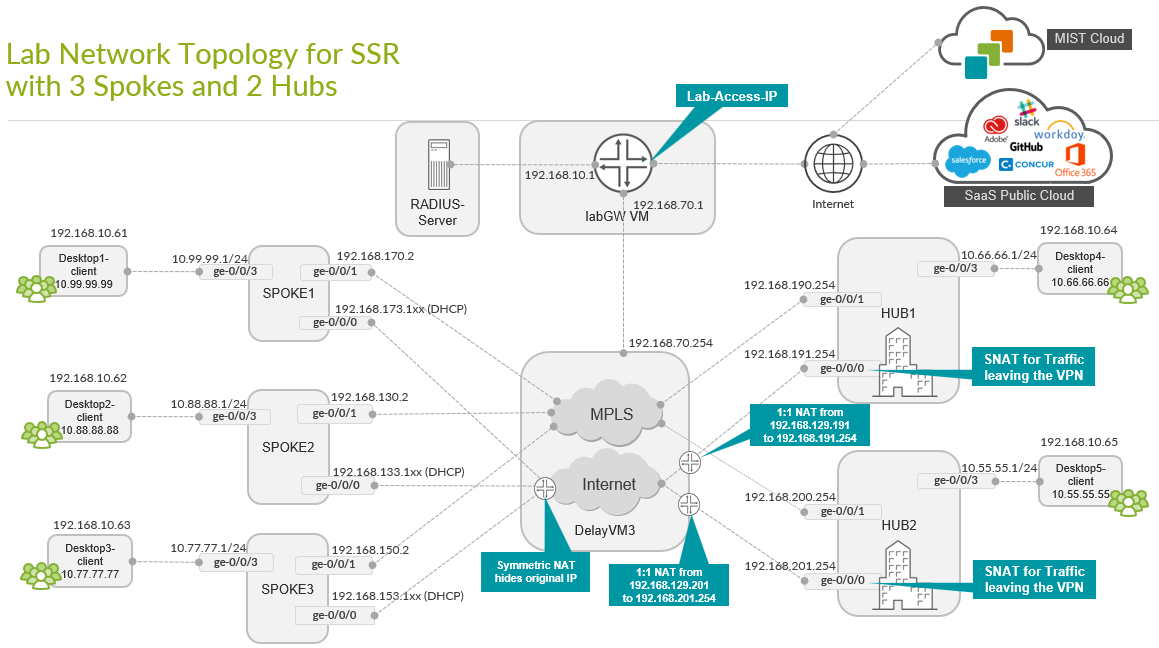
- A base hub-and-spoke design with two independent hubs and three spokes. This serves as the foundational topology. The other topologies are extensions or changes to the base topology to achieve other goals. See Base SD-WAN Topology with Three Spokes and Two Hubs.
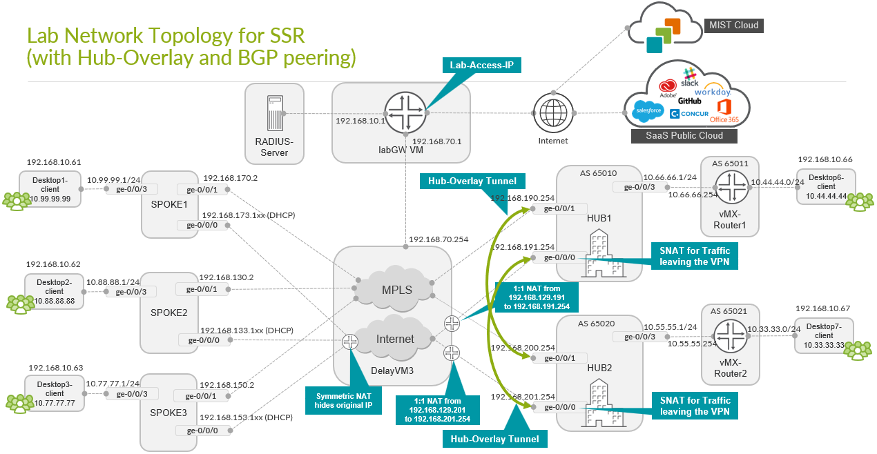
- A topology where the servers at the hub are not directly attached to the LAN interface and there is a router that is placed between the hub and server. This router then exchanges routes using BGP with the hub to advertise its servers and its VPN-reachable networks. We also enabled a hub-to-hub overlay using the hubs’ WAN interfaces to implement a kind of hub redundancy on Layer 3 (L3). See Extended Topology with Hub Overlay and BGP Peering.
- A topology where we form redundant high-availability hub and spokes using the Session Smart Router cluster feature. Those clusters need local Layer 2 (L2) adjacency between the two devices. See High Availability Hub-and-Spoke Using SSR Chassis Cluster Pairs Topology.
- A topology where we add a Juniper Networks® EX Series Switch and a Juniper® Series High-Performance Access Point (AP) at the spoke. This is the most common scenario at a branch where Juniper provided the full-stack networking environment with all components controlled by a single UI in the Juniper Mist™ cloud. The Juniper EX Series Switch can be attached to the Session Smart Router using a single uplink or multiple uplinks via LAG. See Full Stack Topology with Juniper EX Switch and Juniper Mist AP.
- A topology where we extended the above full-stack networking environment with a Juniper EX Series Switch Virtual Chassis and Session Smart Router high-availability cluster. See Extended Full-Stack Topology with Juniper EX Switch as Virtual Chassis and SSR HA Cluster.
Base SD-WAN Topology with Three Spokes and Two Hubs
This lab represents the default structure where we set up the following:
- Installation of three spoke devices
- Installation of two hub devices
- Two underlay paths with different behavior. In the lab, the
underlay address range is
192.168.0.0/16.- MPLS path with private IP addresses.
- Internet path, subjected to NAT.
- An overlay network managed by the enterprise. It is implemented
on the LAN side of hub and spokes. In the lab, the overlay address
range is
10.0.0.0/8.
| Device | Interface | IF-Type | Path | IP Address | Assigned | NAT |
|---|---|---|---|---|---|---|
| Spoke1 | ge-0/0/0 | WAN | INET | 192.168.173.1xx | DHCP | symmetric |
| Spoke1 | ge-0/0/1 | WAN | MPLS | 192.168.170.2 | static | none |
| Spoke1 | ge-0/0/3 | LAN | VPN | 10.99.99.1/24 | static | N/A |
| Spoke2 | ge-0/0/0 | WAN | INET | 192.168.133.1xx | DHCP | symmetric |
| Spoke2 | ge-0/0/1 | WAN | MPLS | 192.168.130.2 | static | none |
| Spoke2 | ge-0/0/3 | LAN | VPN | 10.88.88.1/24 | static | N/A |
| Spoke3 | ge-0/0/0 | WAN | INET | 192.168.153.1xx | DHCP | symmetric |
| Spoke3 | ge-0/0/1 | WAN | MPLS | 192.168.150.2 | static | none |
| Spoke3 | ge-0/0/3 | LAN | VPN | 10.77.77.1/24 | static | N/A |
| Hub1 | ge-0/0/0 | WAN | INET | 192.168.191.254 | static |
Full Cone (1:1) 192.168.129.191 |
| Hub1 | ge-0/0/1 | WAN | MPLS | 192.168.190.254 | static | none |
| Hub1 | ge-0/0/3 | LAN | VPN | 10.66.66.1/24 | static | N/A |
| Hub2 | ge-0/0/0 | WAN | INET | 192.168.201.254 | static |
Full Cone (1:1) 192.168.129.201 |
| Hub2 | ge-0/0/1 | WAN | MPLS | 192.168.200.254 | static | none |
| Hub2 | ge-0/0/3 | LAN | VPN | 10.55.55.1/24 | static | N/A |
In this lab, the emulated public IP addresses are 192.168.129.191 for Hub1 and 192.168.129.201 for Hub2. The spokes connect to these addresses.
Extended Topology with Hub Overlay and BGP Peering
This is a topology where the servers at the hub are not directly attached to the LAN interface. There is a router that is placed between the hub and the server. This router exchanges routes over BGP with the hub to advertise its servers and the VPN-reachable networks. We also enabled a hub-to-hub overlay, using the WAN interfaces of the hubs, as a means of hub redundancy at L3. This prevents a direct connection between the datacenter routers in case services from Hub1 Datacenter need to communicate to services in Hub2 and vice versa. Instead, those communication can be now established through the WAN interfaces of the two hubs.
The two MX routers attached to the LAN interfaces and the following additional networks:
-
10.44.44.0/24attached to the router of Hub1. -
10.33.33.0/24attached to the router of Hub2.
These networks are additionally defined. The hub overlay is an added configuration in the Juniper Mist portal.
High Availability Hub-and-Spoke Using SSR Chassis Cluster Pairs Topology
In this topology, we form redundant high-availability, hub-and-spokes using the Session Smart Router cluster feature. Each cluster is built using the same Session Smart Router device model plus local (L2 adjacency and two additional cables for HA control/fabric. Note that the LAN interfaces are shared with the same IP address and only one link is active at a time using VRRP. On the WAN interfaces, a similar setup is done for MPLS Links as they have a shared static IP address which is not the case for the Internet links.
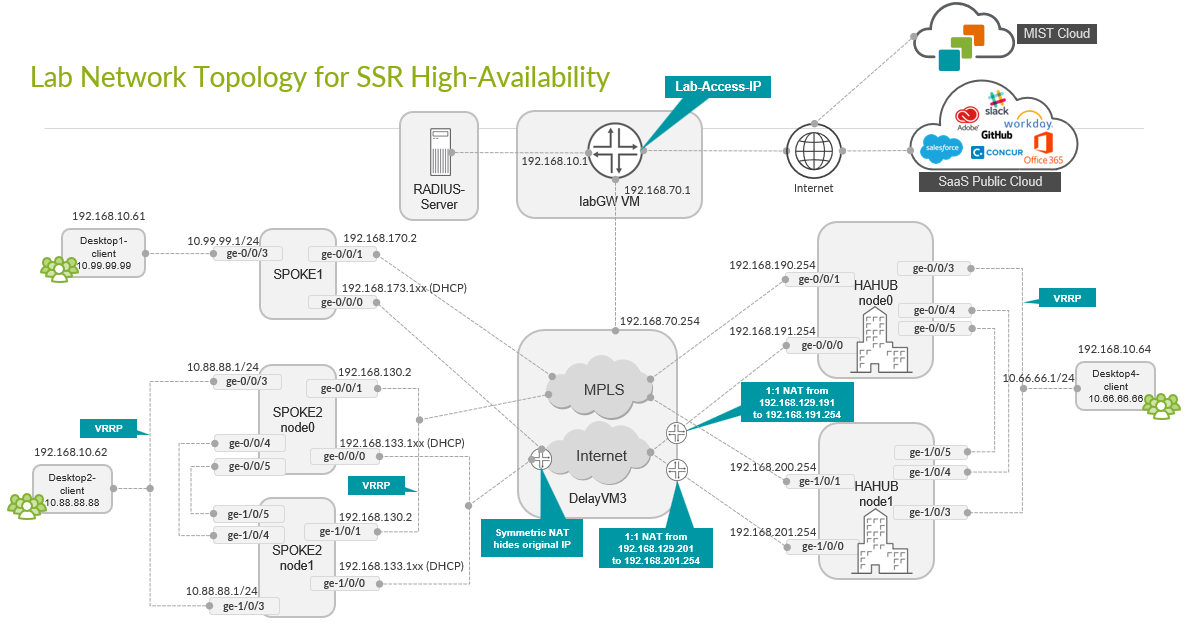
This type of deployment for a hub is impossible in most public clouds since you might have a VM-based hub. This is because the strict rules governing public clouds usually do not allow MAC address moves between interfaces. Consider hub overlay instead.
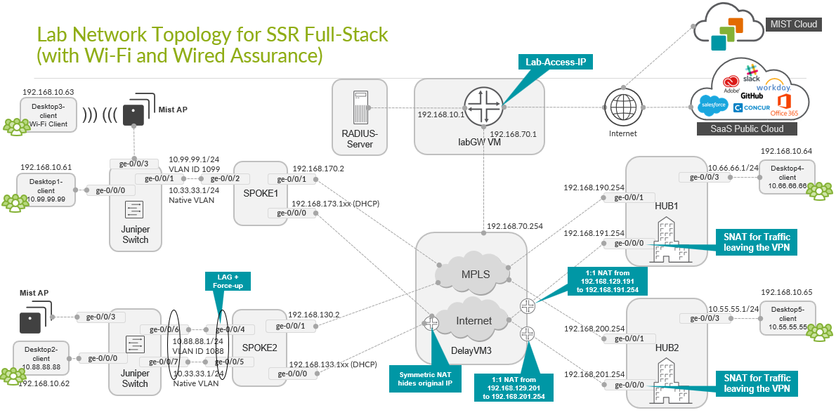
Full Stack Topology with Juniper EX Switch and Juniper Mist AP
In this topology, we are adding Juniper EX Series Switches and Juniper Mist APs to provide an end-to-end, full stack solution to the branch. To boot the EX Series Switch up behind the Session Smart Router as WAN router, we also utilize:
- A DHCP server on the spoke to hand out DHCP address leases to the EX Series Switch, Juniper Mist AP, and all wired and wireless clients.
- One uplink interface between the EX Series Switch and WAN router only.
- Two uplink interfaces between the EX Series Switch and WAN
router with LAG and active LACP.
- Support for force-up is required on one of the uplink ports of the WAN router because initially, the LAG configuration on the EX Series Switch is not present. This configuration allows in-band management of the switch through its revenue ports. Without the force-up feature, you would need a dedicated cable from the management port of the switch to the WAN router or a more complex staging method to form the LAG without losing device management.
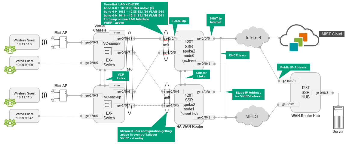
Extended Full-Stack Topology with Juniper EX Switch as Virtual Chassis and SSR HA Cluster
In this Topology, we extended the above full-stack topology using Juniper EX Switches forming a Virtual Chassis with a minimum of two members. To achieve the same redundancy on the WAN router side, we again formed a high-availability cluster using two Session Smart Routers. Also, a LAG was used from each Session Smart Router WAN router node towards the primary and backup nodes of the Virtual Chassis resulting in four uplinks from the Virtual Chassis.