Appendix: Building an Extended Topology with Hub Overlay and BGP Peering
This lab is an extension of the previous lab Appendix: Building a base SD-WAN Topology with Three Spokes and Two Hubs. The underlay connections and spoke implementation are not changed. We add two new changes to this lab:
- We build a hub overlay. This enables sending traffic between
the two hubs directly by exiting the WAN infrastructure. Hence you
enable DC to DC traffic using this topology.
- For traffic steering, we utilize an ECMP-based load-balancing algorithm to have the flows distributed among the two paths between the hubs.
- We introduce data center routers that are attached to the hub LAN interfaces. Those will manage additional resources like servers attached to other interfaces. The additional IP prefixes for those resources will get announced through exterior BGP and propagated through the VPN.
.png)
The following table has the additional device information for the new topology.
| Location | Direct Hub IF | Local AS | Router IF | Router AS | Route propagation | DC Name | DC IP prefix |
|---|---|---|---|---|---|---|---|
| hub1 | 10.66.66.1/24 | 65010 | 10.66.66.254/24 | 65011 | eBGP | DC1 | 10.44.44.0/24 |
| hub2 | 10.55.55.1/24 | 65020 | 10.55.55.254/24 | 65021 | eBGP | DC2 | 10.33.33.0/24 |
The AS numbers selected are self-defined and should be private AS and unique. Do not use AS 65000 as its in use internally already!
Extending Applications
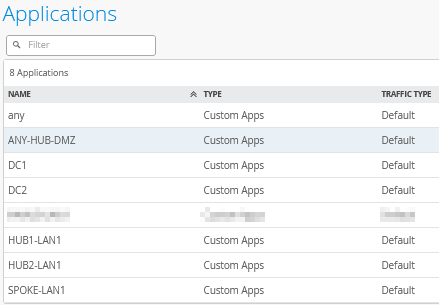
Go to Organization -> Applications and add the following two new applications with the custom IP address ranges the DCs use:
Add a new application and configure the following:
- Name=
DC1 - Type=
Custom Apps - IP Addresses=
10.44.44.0/24
Add another new application and configure the following:
- Name=
DC2 - Type=
Custom Apps - IP Addresses=
10.33.33.0/24
The result should look like the figure below:
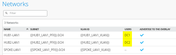
Extending Networks
Go to Organization -> Networks and edit the existing Network “HUB1-LAN”. You need to add a USERS-Object:
- Name=
DC1 - IP Prefixes=
10.44.44.0/24
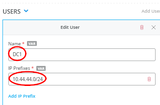
Then, edit the existing Network “HUB2-LAN”. You need to add a USERS-Object:
- Name=
DC2 - IP Prefixes=
10.33.33.0/24
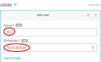
The result should look like the figure below:
Extend the Hub1 Profile
Go to Organization -> Hub Profiles.
Should you choose to use the import option, click on Import Profile and import the below JSON as a file.
{
  "dhcpd_config": {
    "enabled": true
  },
  "ntpOverride": true,
  "dnsOverride": true,
  "service_policies": [
    {
      "name": "spoke-to-hub-dmz",
      "tenants": [
        "SPOKE-LAN1"
      ],
      "services": [
        "HUB1-LAN1",
        "DC1"
      ],
      "action": "allow",
      "path_preference": "HUB-LANS",
      "idp": {
        "enabled": false
      }
    },
    {
      "name": "hub-dmz-to-spoke",
      "tenants": [
        "HUB1-LAN1",
        "DC1.HUB1-LAN1"
      ],
      "services": [
        "SPOKE-LAN1"
      ],
      "action": "allow",
      "local_routing": true,
      "idp": {
        "enabled": false
      }
    },
    {
      "name": "spoke-to-spoke-hairpin",
      "tenants": [
        "SPOKE-LAN1"
      ],
      "services": [
        "SPOKE-LAN1"
      ],
      "action": "allow",
      "local_routing": true,
      "idp": {
        "enabled": false
      }
    },
    {
      "tenants": [
        "HUB1-LAN1",
        "DC1.HUB1-LAN1"
      ],
      "services": [
        "ANY-HUB-DMZ"
      ],
      "action": "allow",
      "path_preference": "CBO",
      "name": "hub-dmz-to-internet",
      "idp": {
        "enabled": false
      }
    },
    {
      "tenants": [
        "SPOKE-LAN1"
      ],
      "services": [
        "any"
      ],
      "action": "allow",
      "name": "spokes-traffic-cbo-on-hub",
      "path_preference": "CBO",
      "idp": {
        "enabled": false
      }
    },
    {
      "name": "remotehub-to-myhub",
      "tenants": [
        "HUB2-LAN1",
        "DC2.HUB2-LAN1"
      ],
      "services": [
        "HUB1-LAN1",
        "DC1"
      ],
      "action": "allow",
      "idp": {
        "enabled": false
      },
      "path_preference": "HUB-LANS"
    },
    {
      "name": "myhub-to-remotehub",
      "tenants": [
        "HUB1-LAN1",
        "DC1.HUB1-LAN1"
      ],
      "services": [
        "HUB2-LAN1",
        "DC2"
      ],
      "action": "allow",
      "idp": {
        "enabled": false
      },
      "path_preference": "REMOTEHUB"
    }
  ],
  "ip_configs": {
    "HUB1-LAN1": {
      "type": "static",
      "ip": "{{HUB1_LAN1_PFX}}.1",
      "netmask": "/24"
    }
  },
  "dns_servers": [
    "8.8.8.8",
    "9.9.9.9"
  ],
  "port_config": {
    "ge-0/0/0": {
      "name": "INET",
      "usage": "wan",
      "aggregated": false,
      "redundant": false,
      "critical": false,
      "disabled": false,
      "wan_type": "broadband",
      "ip_config": {
        "type": "static",
        "ip": "{{WAN0_PFX}}.254",
        "netmask": "/24",
        "gateway": "{{WAN0_PFX}}.1"
      },
      "wan_ext_ip": "{{WAN0_PUBIP}}",
      "disable_autoneg": false,
      "wan_source_nat": {
        "disabled": false
      },
      "vpn_paths": {
        "hub2-INET.OrgOverlay": {
          "role": "spoke"
        },
        "hub1-INET.OrgOverlay": {
          "role": "hub"
        }
      }
    },
    "ge-0/0/1": {
      "name": "MPLS",
      "usage": "wan",
      "aggregated": false,
      "redundant": false,
      "critical": false,
      "disabled": false,
      "wan_type": "broadband",
      "ip_config": {
        "type": "static",
        "ip": "{{WAN1_PFX}}.254",
        "netmask": "/24",
        "gateway": "{{WAN1_PFX}}.1"
      },
      "wan_ext_ip": "{{WAN1_PUBIP}}",
      "disable_autoneg": false,
      "wan_source_nat": {
        "disabled": false
      },
      "vpn_paths": {
        "hub2-MPLS.OrgOverlay": {
          "role": "spoke"
        },
        "hub1-MPLS.OrgOverlay": {
          "role": "hub"
        }
      }
    },
    "ge-0/0/3": {
      "usage": "lan",
      "networks": [
        "HUB1-LAN1"
      ]
    }
  },
  "bgp_config": {
    "DC1": {
      "networks": [
        "HUB1-LAN1"
      ],
      "via": "lan",
      "type": "external",
      "no_readvertise_to_overlay": false,
      "local_as": 65010,
      "hold_time": 90,
      "graceful_restart_time": 120,
      "neighbors": {
        "10.66.66.254": {
          "disabled": false,
          "neighbor_as": 65011
        }
      },
      "disable_bfd": false
    }
  },
  "routing_policies": {},
  "extra_routes": {},
  "path_preferences": {
    "HUB-LANS": {
      "strategy": "ordered",
      "paths": [
        {
          "type": "local",
          "networks": [
            "HUB1-LAN1"
          ]
        }
      ]
    },
    "CBO": {
      "strategy": "ordered",
      "paths": [
        {
          "name": "INET",
          "type": "wan"
        }
      ]
    },
    "REMOTEHUB": {
      "strategy": "ecmp",
      "paths": [
        {
          "name": "hub2-INET.OrgOverlay",
          "type": "vpn"
        },
        {
          "name": "hub2-MPLS.OrgOverlay",
          "type": "vpn"
        }
      ]
    }
  },
  "ospf_areas": {},
  "vrf_instances": {},
  "tunnel_configs": {},
  "oob_ip_config": {
    "type": "dhcp",
    "node1": {
      "type": "dhcp"
    }
  },
  "tunnel_provider_options": {
    "jse": {},
    "zscaler": {}
  },
  "ospf_config": {
    "enabled": false,
    "areas": {}
  },
  "name": "hub1",
  "type": "gateway"
}
Should you decide to configure everything manually in the Juniper Mist portal, then use the following steps.
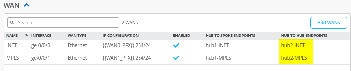
Edit the existing WAN “INET” and add:
- Hub to Hub Endpoint=
hub2-INET
Edit the existing WAN “MPLS” and add:
- Hub to Hub Endpoint=
hub2-MPLS
The result should look like the figure below:
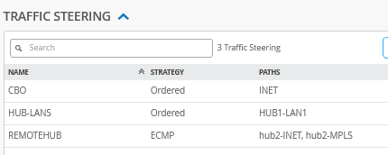
Add the following new traffic steering policy:
- Name=
REMOTEHUB - Strategy=
ECMP - Paths
- Path Type1=
Overlay: hub2-INET - Path Type2=
Overlay: hub2-MPLS
- Path Type1=
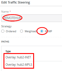
The result should look like the figure below:
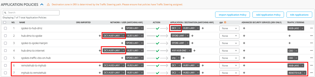
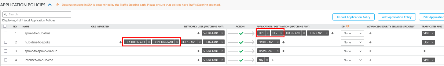
Edit the existing application policies to include the following:
- Number=
1- Name=
spoke-to-hub-dmz - Application=
HUB1-LAN1+DC1
- Name=
- Number=
2- Name=
hub-dmz-to-spoke - Network=
HUB1-LAN1+DC1.HUB1-LAN1
- Name=
- Number=
4- Name=
hub-dmz-to-internet - Network=
HUB1-LAN1+DC1.HUB1-LAN1
- Name=
Add the following two application policies:
- Number=
6- Name=
remoterhub-to-myhub - Network=
HUB2-LAN1+DC2.HUB2-LAN1 - Action=
Pass - Application=
HUB1-LAN+DC1 - Traffic Steering=
HUB-LANS
- Name=
- Number=
7- Name=
myhub-to-remotehub - Network=
HUB1-LAN1+DC1.HUB1-LAN1 - Action=
Pass - Application=
HUB2-LAN1+DC2 - Traffic Steering=
REMOTEHUB
- Name=
The result should look like the figure below:
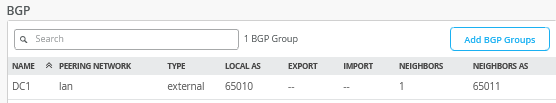
Configure the BGP peering with the data center router as follows:
- Name=
DC1 - Peering Network LAN=
HUB1-LAN1 - Advertise to Overlay=
Enabled/Checked - BFD=
Enabled - Type=
External - Local AS=
65010 - Hold Time=
90 - Graceful Restart Time=
120 - Export=
None - Import=
None - BGP Neighbor
- Neighbor=
Enabled - IP Address=
10.66.66.254 - Neighbor AS=
65011 - Export=
None - Import=
None
- Neighbor=
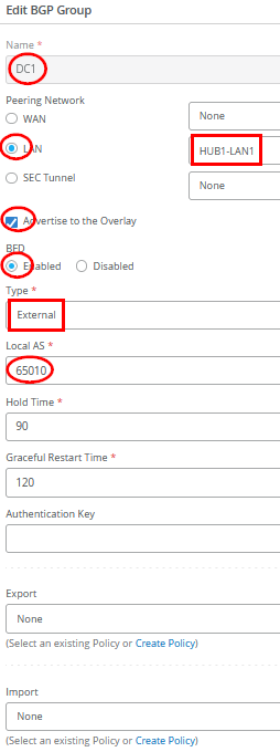
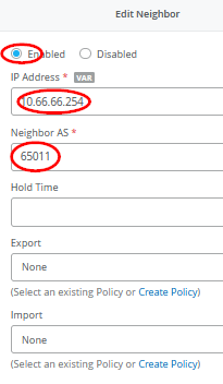
The result should look like the figure below:
Save your results.
Extend the Hub2 Profile
Go to Organization -> Hub Profiles.
Should you choose to use the import option, click on Import Profile and import the below JSON as a file.
{
  "dhcpd_config": {
    "enabled": true
  },
  "ntpOverride": true,
  "dnsOverride": true,
  "service_policies": [
    {
      "name": "spoke-to-hub-dmz",
      "tenants": [
        "SPOKE-LAN1"
      ],
      "services": [
        "HUB2-LAN1",
        "DC2"
      ],
      "action": "allow",
      "path_preference": "HUB-LANS",
      "idp": {
        "enabled": false
      }
    },
    {
      "name": "hub-dmz-to-spoke",
      "tenants": [
        "HUB2-LAN1",
        "DC2.HUB2-LAN1"
      ],
      "services": [
        "SPOKE-LAN1"
      ],
      "action": "allow",
      "local_routing": true,
      "idp": {
        "enabled": false
      }
    },
    {
      "name": "spoke-to-spoke-hairpin",
      "tenants": [
        "SPOKE-LAN1"
      ],
      "services": [
        "SPOKE-LAN1"
      ],
      "action": "allow",
      "local_routing": true,
      "idp": {
        "enabled": false
      }
    },
    {
      "tenants": [
        "HUB2-LAN1",
        "DC2.HUB2-LAN1"
      ],
      "services": [
        "ANY-HUB-DMZ"
      ],
      "action": "allow",
      "path_preference": "CBO",
      "name": "hub-dmz-to-internet",
      "idp": {
        "enabled": false
      }
    },
    {
      "tenants": [
        "SPOKE-LAN1"
      ],
      "services": [
        "any"
      ],
      "action": "allow",
      "name": "spoke-traffic-cbo-on-hub",
      "path_preference": "CBO",
      "idp": {
        "enabled": false
      }
    },
    {
      "name": "remotehub-to-myhub",
      "tenants": [
        "HUB1-LAN1",
        "DC1.HUB1-LAN1"
      ],
      "services": [
        "HUB2-LAN1",
        "DC2"
      ],
      "action": "allow",
      "idp": {
        "enabled": false
      },
      "path_preference": "HUB-LANS"
    },
    {
      "name": "myhub-to-remotehub",
      "tenants": [
        "HUB2-LAN1",
        "DC2.HUB2-LAN1"
      ],
      "services": [
        "HUB1-LAN1",
        "DC1"
      ],
      "action": "allow",
      "idp": {
        "enabled": false
      },
      "path_preference": "REMOTEHUB"
    }
  ],
  "ip_configs": {
    "HUB2-LAN1": {
      "type": "static",
      "ip": "{{HUB2_LAN1_PFX}}.1",
      "netmask": "/24"
    }
  },
  "dns_servers": [
    "8.8.8.8",
    "9.9.9.9"
  ],
  "port_config": {
    "ge-0/0/0": {
      "name": "INET",
      "usage": "wan",
      "aggregated": false,
      "redundant": false,
      "critical": false,
      "disabled": false,
      "wan_type": "broadband",
      "ip_config": {
        "type": "static",
        "ip": "{{WAN0_PFX}}.254",
        "netmask": "/24",
        "gateway": "{{WAN0_PFX}}.1"
      },
      "wan_ext_ip": "{{WAN0_PUBIP}}",
      "disable_autoneg": false,
      "wan_source_nat": {
        "disabled": false
      },
      "vpn_paths": {
        "hub1-INET.OrgOverlay": {
          "role": "spoke"
        },
        "hub2-INET.OrgOverlay": {
          "role": "hub"
        }
      }
    },
    "ge-0/0/1": {
      "name": "MPLS",
      "usage": "wan",
      "aggregated": false,
      "redundant": false,
      "critical": false,
      "disabled": false,
      "wan_type": "broadband",
      "ip_config": {
        "type": "static",
        "ip": "{{WAN1_PFX}}.254",
        "netmask": "/24",
        "gateway": "{{WAN1_PFX}}.1"
      },
      "wan_ext_ip": "{{WAN1_PUBIP}}",
      "disable_autoneg": false,
      "wan_source_nat": {
        "disabled": false
      },
      "vpn_paths": {
        "hub1-MPLS.OrgOverlay": {
          "role": "spoke"
        },
        "hub2-MPLS.OrgOverlay": {
          "role": "hub"
        }
      }
    },
    "ge-0/0/3": {
      "usage": "lan",
      "aggregated": false,
      "redundant": false,
      "networks": [
        "HUB2-LAN1"
      ]
    }
  },
  "bgp_config": {
    "DC2": {
      "networks": [
        "HUB2-LAN1"
      ],
      "via": "lan",
      "type": "external",
      "no_readvertise_to_overlay": false,
      "local_as": 65020,
      "hold_time": 90,
      "graceful_restart_time": 120,
      "neighbors": {
        "10.55.55.254": {
          "disabled": false,
          "neighbor_as": 65021
        }
      },
      "disable_bfd": false
    }
  },
  "routing_policies": {},
  "extra_routes": {},
  "path_preferences": {
    "HUB-LANS": {
      "strategy": "ordered",
      "paths": [
        {
          "type": "local",
          "networks": [
            "HUB2-LAN1"
          ]
        }
      ]
    },
    "CBO": {
      "strategy": "ordered",
      "paths": [
        {
          "name": "INET",
          "type": "wan"
        }
      ]
    },
    "REMOTEHUB": {
      "strategy": "ecmp",
      "paths": [
        {
          "name": "hub1-INET.OrgOverlay",
          "type": "vpn"
        },
        {
          "name": "hub1-MPLS.OrgOverlay",
          "type": "vpn"
        }
      ]
    }
  },
  "ospf_areas": {},
  "vrf_instances": {},
  "tunnel_configs": {},
  "oob_ip_config": {
    "type": "dhcp",
    "node1": {
      "type": "dhcp"
    }
  },
  "tunnel_provider_options": {
    "jse": {},
    "zscaler": {}
  },
  "ospf_config": {
    "enabled": false,
    "areas": {}
  },
  "name": "hub2",
  "type": "gateway"
}
Should you decide to configure everything manually in the Juniper Mist portal, then use the following steps.
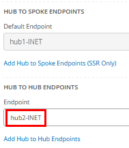
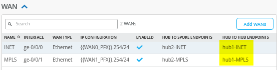
Edit the existing WAN “INET” and add:
- Hub to Hub Endpoint=
hub1-INET
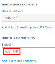
Edit the existing WAN “MPLS” and add:
- Hub to Hub Endpoint=
hub1-MPLS
The result should look like the figure below:
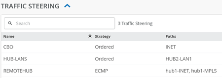
Add the following new traffic steering policy:
- Name=
REMOTEHUB - Strategy=
ECMP - Paths
- Path Type1=
Overlay: hub1-INET - Path Type2=
Overlay: hub1-MPLS
- Path Type1=
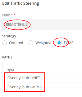
The result should look like the figure below:
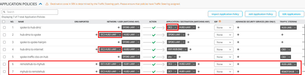
Edit the existing application policies to include the following:
- Number=
1- Name=
spoke-to-hub-dmz - Application=
HUB2-LAN1+DC2
- Name=
- Number=
2- Name=
hub-dmz-to-spoke - Network=
HUB2-LAN1+DC2.HUB2-LAN1
- Name=
- Number=
4- Name=
hub-dmz-to-internet - Network=
HUB2-LAN1+DC2.HUB2-LAN1
- Name=
Add the following two application policies:
- Number=
6- Name=
remoterhub-to-myhub - Network=
HUB1-LAN1+DC1.HUB1-LAN1 - Action=
Pass - Application=
HUB2-LAN+DC2 - Traffic Steering=
HUB-LANS
- Name=
- Number=
7- Name=
myhub-to-remotehub - Network=
HUB2-LAN1+DC2.HUB1-LAN1 - Action=
Pass - Application=
HUB1-LAN1+DC1 - Traffic Steering=
REMOTEHUB
- Name=
The result should look like the figure below:
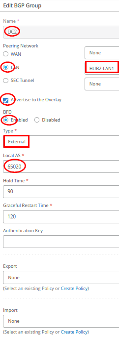
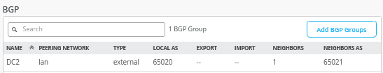
Configure the BGP peering with the data center router as follows:
- Name=
DC2 - Peering Network LAN=
HUB2-LAN1 - Advertise to Overlay=
Enabled/Checked - BFD=
Enabled - Type=
External - Local AS=
65020 - Hold Time=
90 - Graceful Restart Time=
120 - Export=
None - Import=
None - BGP Neighbor
- Neighbor=
Enabled - IP Address=
10.55.55.254 - Neighbor AS=
65021 - Export=
None - Import=
None
- Neighbor=
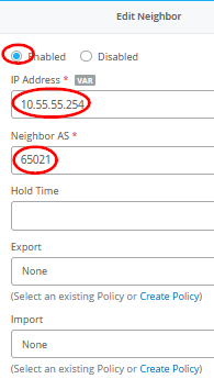
The result should look like the figure below:
Save your results.
Extend the Spokes Template
The new DC1 and DC2 subnets are added here to the existing rules for visibility.
Edit the following Application Policies:
- Number=
1- Name=
spoke-to-hub-dmz - Application=
HUB1-LAN1+HUB2-LAN1+DC1+DC2
- Name=
- Number=
2- Name=
hub-dmz-to-spoke - Network=
HUB1-LAN1+HUB2-LAN1+DC1.HUB1-LAN1+DC2.HUB1-LAN1
- Name=
Configuring DC Routers
There are many ways your data center routers can be configured to share routes using eBGP with the hub they are attached to. In our example below, we use an Ubuntu Linux-based VM with the BIRD Internet Routing Daemon for this exchange. Feel free to reuse or utilize other frameworks.
The below example shares the network and BIRD configuration used on DC-Router1 of this topology:
              cat /etc/netplan/01-netcfg.yaml
network:
  version: 2
  renderer: networkd
  ethernets:
    ens3:
      addresses:
        - 192.168.10.71/24
      dhcp4: false
    ens4:
      dhcp4: false
    ens5:
      dhcp4: false
  vlans:
    vlan1066:
      id: 1066
      link: ens5
      addresses: [10.66.66.254/24]
      gateway4: 10.66.66.1
      nameservers:
        addresses: [8.8.8.8, 9.9.9.9]
    vlan1044:
      id: 1044
      link: ens4
      addresses: [10.44.44.1/24]
#
# enable forwarding between interfaces
echo 'net.ipv4.ip_forward=1' >>/etc/sysctl.conf
              sudo sysctl -p
#
# install bgp daemon
apt-get install -y bird
#
cp /etc/bird/bird.conf /etc/bird/bird.conf.orig
#
# configure bgp daemon
cat<<EOF >/etc/bird/bird.conf
# Configure logging
log syslog all;
# Override router ID
router id 10.66.66.254;
# This pseudo-protocol performs synchronization between BIRD's routing
# tables and the kernel. If your kernel supports multiple routing tables
# (as Linux 2.2.x does), you can run multiple instances of the kernel
# protocol and synchronize different kernel tables with different BIRD tables.
protocol kernel {
# learn;          # Learn all alien routes from the kernel
  persist;        # Don't remove routes on bird shutdown
  scan time 20;       # Scan kernel routing table every 20 seconds
# import none;        # Default is import all
  export all;     # Default is export none
# kernel table 5;     # Kernel table to synchronize with (default: main)
}
# This pseudo-protocol watches all interface up/down events.
protocol device {
  scan time 10;       # Scan interfaces every 10 seconds
}
# add out local IF towards desktop6 VM to the table
protocol direct direct1 {
    interface "vlan1044";
}
#BGP Configuration
protocol bgp Spoke1 {
        import all;
        export where proto = "direct1";
        local as 65011;
                     neighbor 10.66.66.1 as 65010;
}
EOF
#
# disable and restart our bgp-daemon with the new config
systemctl disable bird
              systemctl restart bird
The below example shares the network and BIRD configuration used on DC-Router2 of this topology:
              cat /etc/netplan/01-netcfg.yaml
network:
  version: 2
  renderer: networkd
  ethernets:
    ens3:
      addresses:
        - 192.168.10.72/24
      dhcp4: false
    ens4:
      dhcp4: false
    ens5:
      dhcp4: false
  vlans:
    vlan1055:
      id: 1055
      link: ens5
      addresses: [10.55.55.254/24]
      gateway4: 10.55.55.1
      nameservers:
        addresses: [8.8.8.8, 9.9.9.9]
    vlan1033:
      id: 1033
      link: ens4
      addresses: [10.33.33.1/24]
.
# enable forwarding between interfaces
echo 'net.ipv4.ip_forward=1' >>/etc/sysctl.conf
              sudo sysctl -p
#
# install bgp daemon
apt-get install -y bird
#
cp /etc/bird/bird.conf /etc/bird/bird.conf.orig
#
# configure bgp daemon
cat<<EOF >/etc/bird/bird.conf
# Configure logging
log syslog all;
# Override router ID
router id 10.55.55.254;
# This pseudo-protocol performs synchronization between BIRD's routing
# tables and the kernel. If your kernel supports multiple routing tables
# (as Linux 2.2.x does), you can run multiple instances of the kernel
# protocol and synchronize different kernel tables with different BIRD tables.
protocol kernel {
# learn;          # Learn all alien routes from the kernel
  persist;        # Don't remove routes on bird shutdown
  scan time 20;       # Scan kernel routing table every 20 seconds
# import none;        # Default is import all
  export all;     # Default is export none
# kernel table 5;     # Kernel table to synchronize with (default: main)
}
# This pseudo-protocol watches all interface up/down events.
protocol device {
  scan time 10;       # Scan interfaces every 10 seconds
}
# add out local IF towards desktop6 VM to the table
protocol direct direct1 {
    interface "vlan1033";
}
#BGP Configuration
protocol bgp Spoke1 {
        import all;
        export where proto = "direct1";
        local as 65021;
                     neighbor 10.55.55.1 as 65020;
}
EOF
#
# disable and restart our bgp-daemon with the new config
systemctl disable bird
              systemctl restart bird
Test your network configuration
After the configuration is done, we can now test the new network configuration and verify the traffic between the two data centers via the two hubs.
The configuration on the Router1 VM now displays the exchanged
routes both locally and within the BIRD process. Among these, key
routes include the direct interface route to Hub2
(10.55.55.0/24) and the propagated data center route
from DC2 (10.33.33.0/24).
root@router1:~# ip route
default via 10.66.66.1 dev vlan1066 proto static
10.0.0.0/8 via 10.66.66.1 dev vlan1066 proto bird
10.33.33.0/24 via 10.66.66.1 dev vlan1066 proto bird
10.44.44.0/24 dev vlan1044 proto kernel scope link src 10.44.44.1
10.55.55.0/24 via 10.66.66.1 dev vlan1066 proto bird
10.66.66.0/24 dev vlan1066 proto kernel scope link src 10.66.66.254
10.77.77.0/24 via 10.66.66.1 dev vlan1066 proto bird
10.88.88.0/24 via 10.66.66.1 dev vlan1066 proto bird
10.99.99.0/24 via 10.66.66.1 dev vlan1066 proto bird
192.168.10.0/24 dev ens3 proto kernel scope link src 192.168.10.71
#
# check the BGP daemon
root@router1:~# birdc
BIRD 1.6.8 ready.
bird> show route
0.0.0.0/0          via 10.66.66.1 on vlan1066 [Spoke1 12:29:03] ! (100) [AS65000?]
10.0.0.0/8         via 10.66.66.1 on vlan1066 [Spoke1 12:29:03] * (100) [AS65000?]
10.88.88.0/24      via 10.66.66.1 on vlan1066 [Spoke1 12:29:03] * (100) [AS65000?]
10.66.66.0/24      via 10.66.66.1 on vlan1066 [Spoke1 12:29:03] ! (100) [AS65000?]
10.77.77.0/24      via 10.66.66.1 on vlan1066 [Spoke1 12:29:03] * (100) [AS65000?]
10.44.44.0/24      dev vlan1044 [direct1 12:24:39] * (240)
10.33.33.0/24      via 10.66.66.1 on vlan1066 [Spoke1 12:35:45] * (100) [AS65021i]
10.55.55.0/24      via 10.66.66.1 on vlan1066 [Spoke1 12:29:03] * (100) [AS65000?]
10.99.99.0/24      via 10.66.66.1 on vlan1066 [Spoke1 12:29:03] * (100) [AS65000?]
The configuration on the Router2 VM now displays the exchanged
routes both locally and within the BIRD process. Among these, key
routes include the direct interface route to Hub2
(10.66.66.0/24) and the propagated data center route
from DC1 (10.44.44.0/24).
root@router2:~# ip route
default via 10.55.55.1 dev vlan1055 proto static
10.0.0.0/8 via 10.55.55.1 dev vlan1055 proto bird
10.33.33.0/24 dev vlan1033 proto kernel scope link src 10.33.33.1
10.44.44.0/24 via 10.55.55.1 dev vlan1055 proto bird
10.55.55.0/24 dev vlan1055 proto kernel scope link src 10.55.55.254
10.66.66.0/24 via 10.55.55.1 dev vlan1055 proto bird
10.77.77.0/24 via 10.55.55.1 dev vlan1055 proto bird
10.88.88.0/24 via 10.55.55.1 dev vlan1055 proto bird
10.99.99.0/24 via 10.55.55.1 dev vlan1055 proto bird
192.168.10.0/24 dev ens3 proto kernel scope link src 192.168.10.72
#
# check the BGP daemon
root@router2:~# birdc
BIRD 1.6.8 ready.
bird> show route
0.0.0.0/0          via 10.55.55.1 on vlan1055 [Spoke1 12:35:46] ! (100) [AS65000?]
10.0.0.0/8         via 10.55.55.1 on vlan1055 [Spoke1 12:35:46] * (100) [AS65000?]
10.88.88.0/24      via 10.55.55.1 on vlan1055 [Spoke1 12:35:46] * (100) [AS65000?]
10.66.66.0/24      via 10.55.55.1 on vlan1055 [Spoke1 12:35:46] * (100) [AS65000?]
10.77.77.0/24      via 10.55.55.1 on vlan1055 [Spoke1 12:35:46] * (100) [AS65000?]
10.44.44.0/24      via 10.55.55.1 on vlan1055 [Spoke1 12:35:46] * (100) [AS65011i]
10.33.33.0/24      dev vlan1033 [direct1 12:35:44] * (240)
10.55.55.0/24      via 10.55.55.1 on vlan1055 [Spoke1 12:35:46] ! (100) [AS65000?]
10.99.99.0/24      via 10.55.55.1 on vlan1055 [Spoke1 12:35:46] * (100) [AS65000?]
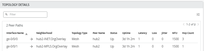
When you go to WAN Edges -> hub1-site -> hub1 you can see the additional overlay tunnels:
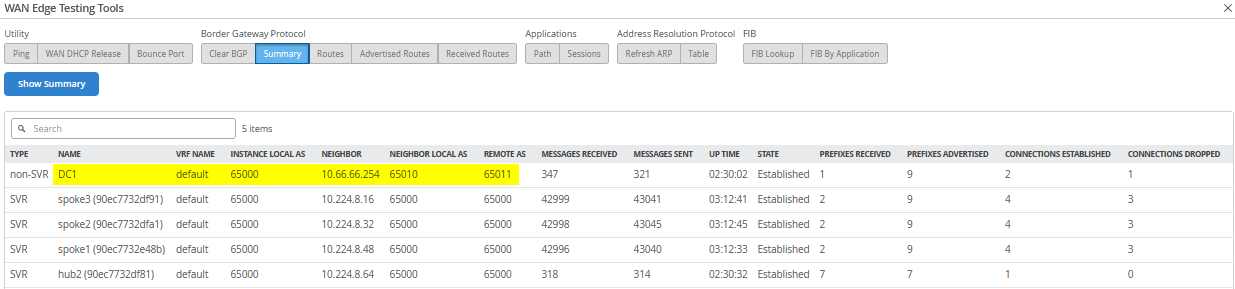
Go further to Utilities -> Testing Tools and click on BGP – Summary you can see the BGP neighbor summary on Hub1:
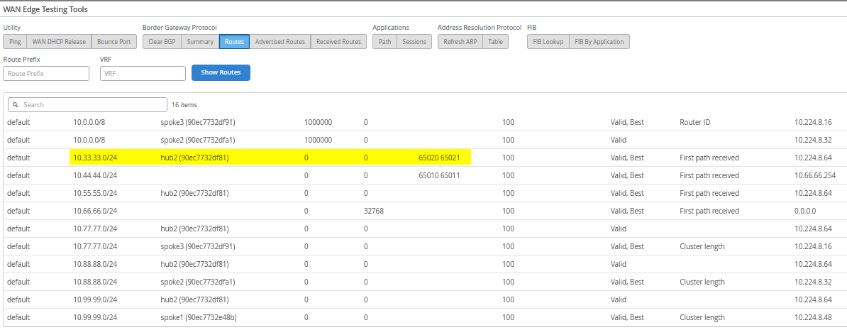
Then, check the routes in the system. Here, it’s important
to receive the remote DC2 route 10.33.33.0/24 .
Now check the traffic utilizing the desktop6 VM which acts as a
service in DC1 with the IP address 10.44.44.44:
# ping hub1 local interface
root@desktop6:~# ping -c3 10.66.66.1
PING 10.66.66.1 (10.66.66.1) 56(84) bytes of data.
64 bytes from 10.66.66.1: icmp_seq=1 ttl=127 time=0.757 ms
64 bytes from 10.66.66.1: icmp_seq=2 ttl=127 time=0.769 ms
64 bytes from 10.66.66.1: icmp_seq=3 ttl=127 time=0.776 ms
#
# check connection to internet via hub CBO
root@desktop6:~# ping -c3 8.8.8.8
PING 8.8.8.8 (8.8.8.8) 56(84) bytes of data.
64 bytes from 8.8.8.8: icmp_seq=1 ttl=50 time=6.34 ms
64 bytes from 8.8.8.8: icmp_seq=2 ttl=50 time=3.78 ms
64 bytes from 8.8.8.8: icmp_seq=3 ttl=50 time=3.81 ms
#
# check connection to spoke1
root@desktop6:~# ping -c3 10.99.99.99
PING 10.99.99.99 (10.99.99.99) 56(84) bytes of data.
64 bytes from 10.99.99.99: icmp_seq=1 ttl=60 time=4.08 ms
64 bytes from 10.99.99.99: icmp_seq=2 ttl=60 time=1.65 ms
64 bytes from 10.99.99.99: icmp_seq=3 ttl=60 time=1.65 ms
#
# verify connection to DC2 local hub LAN
root@desktop6:~# ping -c3 10.55.55.55
PING 10.55.55.55 (10.55.55.55) 56(84) bytes of data.
64 bytes from 10.55.55.55: icmp_seq=1 ttl=58 time=2.98 ms
64 bytes from 10.55.55.55: icmp_seq=2 ttl=58 time=1.52 ms
64 bytes from 10.55.55.55: icmp_seq=3 ttl=58 time=1.45 ms
The most important check is to reach the desktop7 VM IP address
10.33.33.33 which acts as a service in the remote DC2.
This verifies the hub-to-hub overlay is working as expected.
root@desktop6:~# ping 10.33.33.33
PING 10.33.33.33 (10.33.33.33) 56(84) bytes of data.
64 bytes from 10.33.33.33: icmp_seq=1 ttl=59 time=3.53 ms
64 bytes from 10.33.33.33: icmp_seq=2 ttl=59 time=1.88 ms
64 bytes from 10.33.33.33: icmp_seq=3 ttl=59 time=1.84 ms
64 bytes from 10.33.33.33: icmp_seq=4 ttl=59 time=1.78 ms
64 bytes from 10.33.33.33: icmp_seq=5 ttl=59 time=1.83 ms
.
.
Let the ping 10.33.33.33 on desktop6 VM
continuously run and then check on Hub1 Applications
– Session with the application name
HUB2-LAN1 as the destination. The reverse traffic
source and destination IP will indirectly determine which traffic
path is used for this traffic which is MPLS as seen in the figure
below:

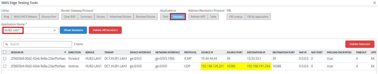
Stop the ping and start a new continuous ping to
10.33.33.1 on the desktop6 VM as we need a different
destination IP address now.
root@desktop6:~# ping 10.33.33.1
PING 10.33.33.1 (10.33.33.1) 56(84) bytes of data.
64 bytes from 10.33.33.1: icmp_seq=1 ttl=58 time=2.80 ms
64 bytes from 10.33.33.1: icmp_seq=2 ttl=58 time=1.46 ms
64 bytes from 10.33.33.1: icmp_seq=3 ttl=58 time=1.55 ms
64 bytes from 10.33.33.1: icmp_seq=4 ttl=58 time=1.52 ms
.
.
Then, check on Hub1 Applications –
Session with the application name HUB2-LAN1
as the destination. The reverse traffic source and destination IP
will indirectly determine which traffic path is used for this
traffic which is INET as seen in the figure below. This verifies
that the ECMP-based traffic steering between the two Hubs is
working as expected.
The final test involves verifying that a VM connected to a spoke can access resources in both DC1 and DC2. This is demonstrated below using the desktop1 VM:
# check connection to DC1
root@desktop1:~# ping -c3 10.44.44.44
PING 10.44.44.44 (10.44.44.44) 56(84) bytes of data.
64 bytes from 10.44.44.44: icmp_seq=1 ttl=58 time=2.84 ms
64 bytes from 10.44.44.44: icmp_seq=2 ttl=58 time=1.51 ms
64 bytes from 10.44.44.44: icmp_seq=3 ttl=58 time=1.52 ms
#
# check connection to DC2
root@desktop1:~# ping -c3 10.33.33.33
PING 10.33.33.33 (10.33.33.33) 56(84) bytes of data.
64 bytes from 10.33.33.33: icmp_seq=1 ttl=58 time=3.82 ms
64 bytes from 10.33.33.33: icmp_seq=2 ttl=58 time=1.37 ms
64 bytes from 10.33.33.33: icmp_seq=3 ttl=58 time=1.41 ms