Appendix: Building a High Availability Hub-and-Spoke Using SSR Chassis Cluster Pairs Topology
This lab builds on the previous lab Appendix: Building a base SD-WAN Topology with Three Spokes and Two Hubs. The underlay connections change a bit here.
- Each pair of devices configured for high availability must have two direct links between them. This is a mandatory requirement, just like ensuring both devices are running the same software version to maintain consistent technical specifications and seamless failover operation.
- To keep the lab setup simple, we did not modify the IP addressing on the clustered hub's WAN interfaces. Avoid using redundant interface configurations on these links, as only one of the two would be active at a time. In the recommended configuration, all four links remain active simultaneously.
- On the clustered hub's LAN interface, link redundancy is configured, allowing only one active link at a time. VRRP is used to manage failover between the two cluster nodes.
- On the clustered spoke WAN interface, we’ve configured
the following:
- The Internet path uses DHCP leases, hence you cannot configure link redundancy here. You can attach them to the same broadband router as indicated in the topology and each will receive its own IP address from the same subnet.
- The MPLS path uses a single static IP address and is configured with link redundancy. As shown in the topology, both links can connect to the same PE router, but only one will be active at a time. VRRP handles failover between the two cluster nodes.
- Link redundancy is configured on the clustered spoke’s LAN interface, allowing only one link to be active at a time. VRRP is used to enable failover between the two cluster nodes.
With this topology, you can test all possible failover scenarios for the JVD, but you may need to adapt this for an individual deployment environment.
.png)
Create a Site and Extend Applications and Networks
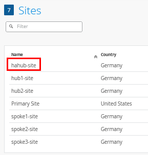
Go to Organization -> Site Configuration and create a new site called “hahub-site”. This time there is no need to configure site variables as the hub profile will be unique anyway. The result is displayed below:
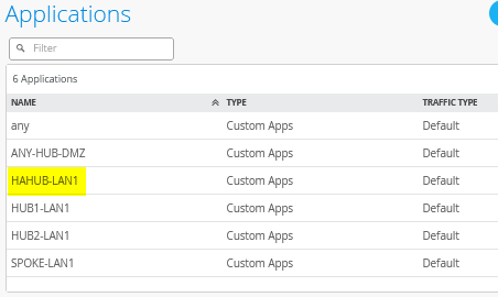
Then, go Organization -> Applications and create a new custom application like the following:
- Name=
HAHUB-LAN1 - Type=
Custom Apps - IP Address=
10.66.66.0/24
The result should look like the figure below:
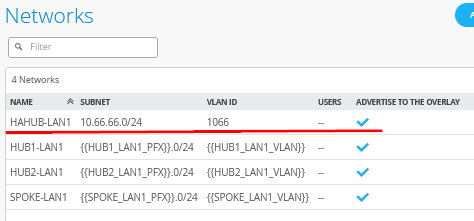
Then go Organization -> Networks and create a new network like:
- Name=
HAHUB-LAN1 - Subnet IP Address=
10.66.66.0 - Prefix Length=
24(we only use a /24 netmask in our example for ease of use) - VLAN ID=
1066 - Access to Mist Cloud=
Checked/Enabled - Advertised via Overlay=
Checked/Enabled
The result should look like the figure below:
Create a High-Availability Hub Profile
Go to Organization -> Hub Profiles.
Should you choose to use the import option, click on Import Profile and import the below JSON as a file.
{
  "dhcpd_config": {
    "enabled": true
  },
  "ntpOverride": true,
  "dnsOverride": true,
  "service_policies": [
    {
      "name": "spoke-to-hub-dmz",
      "tenants": [
        "SPOKE-LAN1"
      ],
      "services": [
        "HAHUB-LAN1"
      ],
      "action": "allow",
      "path_preference": "HUB-LANS",
      "idp": {
        "enabled": false
      }
    },
    {
      "name": "hub-dmz-to-spoke",
      "tenants": [
        "HAHUB-LAN1"
      ],
      "services": [
        "SPOKE-LAN1"
      ],
      "action": "allow",
      "local_routing": true,
      "idp": {
        "enabled": false
      }
    },
    {
      "name": "spoke-to-spoke-hairpin",
      "tenants": [
        "SPOKE-LAN1"
      ],
      "services": [
        "SPOKE-LAN1"
      ],
      "action": "allow",
      "local_routing": true,
      "idp": {
        "enabled": false
      }
    },
    {
      "tenants": [
        "HAHUB-LAN1"
      ],
      "services": [
        "ANY-HUB-DMZ"
      ],
      "action": "allow",
      "name": "hub-dmz-to-internet",
      "idp": {
        "enabled": false
      },
      "path_preference": "CBO"
    },
    {
      "tenants": [
        "SPOKE-LAN1"
      ],
      "services": [
        "any"
      ],
      "action": "allow",
      "name": "spokes-traffic-cbo-on-hub",
      "idp": {
        "enabled": false
      },
      "path_preference": "CBO"
    }
  ],
  "ip_configs": {
    "HAHUB-LAN1": {
      "type": "static",
      "ip": "10.66.66.1",
      "netmask": "/24"
    }
  },
  "dns_servers": [
    "8.8.8.8",
    "9.9.9.9"
  ],
  "port_config": {
    "ge-0/0/0": {
      "name": "N0-INET",
      "usage": "wan",
      "aggregated": false,
      "redundant": false,
      "critical": false,
      "disabled": false,
      "wan_type": "broadband",
      "ip_config": {
        "type": "static",
        "ip": "192.168.191.254",
        "netmask": "/24",
        "gateway": "192.168.191.1"
      },
      "wan_ext_ip": "192.168.129.191",
      "disable_autoneg": false,
      "wan_source_nat": {
        "disabled": false
      },
      "vpn_paths": {
        "hahub-N0-INET.OrgOverlay": {
          "role": "hub"
        }
      }
    },
    "ge-0/0/1": {
      "name": "N0-MPLS",
      "usage": "wan",
      "aggregated": false,
      "redundant": false,
      "critical": false,
      "disabled": false,
      "wan_type": "broadband",
      "ip_config": {
        "type": "static",
        "ip": "192.168.190.254",
        "netmask": "/24",
        "gateway": "192.168.190.1"
      },
      "disable_autoneg": false,
      "wan_source_nat": {
        "disabled": false
      },
      "vpn_paths": {
        "hahub-N0-MPLS.OrgOverlay": {
          "role": "hub"
        }
      }
    },
    "ge-1/0/0": {
      "name": "N1-INET",
      "usage": "wan",
      "aggregated": false,
      "redundant": false,
      "critical": false,
      "disabled": false,
      "wan_type": "broadband",
      "ip_config": {
        "type": "static",
        "ip": "192.168.201.254",
        "netmask": "/24",
        "gateway": "192.168.201.1"
      },
      "wan_ext_ip": "192.168.129.201",
      "disable_autoneg": false,
      "wan_source_nat": {
        "disabled": false
      },
      "vpn_paths": {
        "hahub-N1-INET.OrgOverlay": {
          "role": "hub"
        }
      }
    },
    "ge-1/0/1": {
      "name": "N1-MPLS",
      "usage": "wan",
      "aggregated": false,
      "redundant": false,
      "critical": false,
      "disabled": false,
      "wan_type": "broadband",
      "ip_config": {
        "type": "static",
        "ip": "192.168.200.254",
        "netmask": "/24",
        "gateway": "192.168.200.1"
      },
      "disable_autoneg": false,
      "wan_source_nat": {
        "disabled": false
      },
      "vpn_paths": {
        "hahub-N1-MPLS.OrgOverlay": {
          "role": "hub"
        }
      }
    },
    "ge-0/0/3,ge-1/0/3": {
      "networks": [
        "HAHUB-LAN1"
      ],
      "usage": "lan",
      "aggregated": false,
      "redundant": true,
      "reth_idx": 3,
      "reth_node": "node0",
      "critical": false,
      "disabled": false
    }
  },
  "bgp_config": {},
  "routing_policies": {},
  "extra_routes": {},
  "path_preferences": {
    "HUB-LANS": {
      "strategy": "ordered",
      "paths": [
        {
          "type": "local",
          "networks": [
            "HAHUB-LAN1"
          ]
        }
      ]
    },
    "CBO": {
      "strategy": "ordered",
      "paths": [
        {
          "name": "N0-INET",
          "type": "wan"
        },
        {
          "name": "N1-INET",
          "type": "wan"
        }
      ]
    }
  },
  "ospf_areas": {},
  "vrf_instances": {},
  "tunnel_configs": {},
  "oob_ip_config": {
    "type": "dhcp",
    "node1": {
      "type": "dhcp"
    }
  },
  "tunnel_provider_options": {
    "jse": {},
    "zscaler": {}
  },
  "ospf_config": {
    "enabled": false,
    "areas": {}
  },
  "name": "hahub",
  "type": "gateway"
}
Should you decide to configure everything manually in the Juniper Mist portal, then use the following steps.
Create a new hub profile with the name “hahub”. Do not change this name as it has dependencies later.
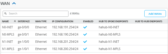
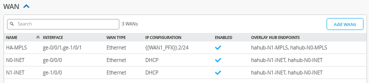
Configure a first WAN interface for Node0 as follows:
- Name=
N0-INETthis indicates which topology and node it’s going to use. - WAN Type=
Ethernet - Interface=
ge-0/0/0as all interfaces starting withge-0are on node0. - IP Address=
192.168.191.254 - Prefix Length=
24 - Gateway=
192.168.191.1 - Source NAT=
Interface - Override for Public IP=
Checked/Enabled - Public IP=
192.168.129.191 - The Overlay Hub Endpoint will be automatically generated and should be “hahub-N0-INET”.
Configure a second WAN interface for Node0 as follows:
- Name=
N0-MPLSthis indicates which topology and node it’s going to use. - WAN Type=
Ethernet - Interface=
ge-0/0/1as all interfaces starting withge-0are on node0. - IP Address=
192.168.190.254 - Prefix Length=
24 - Gateway=
192.168.190.1 - Source NAT=
Interface - Public IP=
192.168.190.254(auto inserted) - The Overlay Hub Endpoint will be automatically generated and should be “hahub-N0-MPLS”.
Configure a first WAN interface for Node1 as follows:
- Name=
N1-INETthis indicates which topology and node it’s going to use. - WAN Type=
Ethernet - Interface=
ge-1/0/0as all interfaces starting withge-1are on node1. - IP Address=
192.168.201.254 - Prefix Length=
24 - Gateway=
192.168.201.1 - Source NAT=
Interface - Override for Public IP=
Checked/Enabled - Public IP=
192.168.129.201 - The Overlay Hub Endpoint will be automatically generated and should be “hahub-N1-INET”.
Configure a second WAN interface for Node1 as follows:
- Name=
N1-MPLSthis indicates which Topology and Node it’s going to use. - WAN Type=
Ethernet - Interface=
ge-1/0/1as all interfaces starting withge-1are on node1. - IP Address=
192.168.200.254 - Prefix Length=
24 - Gateway=
192.168.200.1 - Source NAT=
Interface - Public IP=
192.168.200.254(auto inserted) - The Overlay Hub Endpoint will be automatically generated and should be “hahub-N1-MPLS”.
The result should look like the figure below:
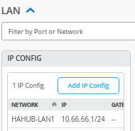
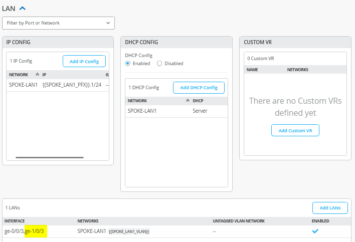
Add a LAN IP config now with the following configuration:
- Network=
HAHUB-LAN1 - IP Address=
10.66.66.1 - Prefix Length=
24
The result should look like the figure below:
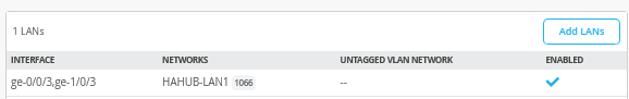
Add a LAN interface now with the following configuration:
- Interface=
ge-0/0/3,ge-1/0/3 - Redundant=
Checked/Enabled- Redundant Index=
3(this is not required for an SSR, but we add it for compatibility) - Primary Node=
node0
- Redundant Index=
- Networks=
HAHUB-LAN1 - Untagged VLAN=
None
The result should look like the figure below:
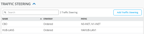
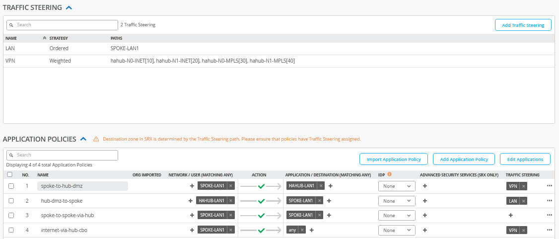
Now we need to define two traffic steering rules. The first rule has the following configuration:
- Name=
HUB-LANS - Strategy=
Ordered - Paths
- Path1 Type=
LAN: HAHUB1-LAN1
- Path1 Type=
The second rule has the following configuration:
- Name=
CBO - Strategy=
Ordered - Paths
- Path1 Type=
WAN: N0-INET - Path2 Type=
WAN: N1-INET
- Path1 Type=
The result should look like the figure below:
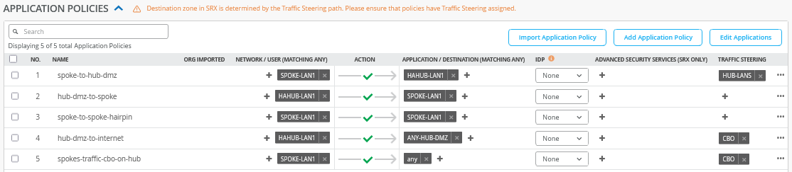
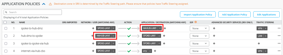
Configure or import the following application policies:
- Number=
1- Name=
spoke-to-hub-dmz - Network=
SPOKE-LAN1 - Action=
Pass - Application=
HAHUB-LAN1 - Traffic Steering=
HUB-LANS
- Name=
- Number=
2- Name=
hub-dmz-to-spoke - Network=
HAHUB-LAN1 - Action=
Pass - Application=
SPOKE-LAN1 - Traffic Steering=
N/A
- Name=
- Number=
3- Name=
spoke-to-spoke-hairpin - Network=
SPOKE-LAN1 - Action=
Pass - Application=
SPOKE-LAN1 - Traffic Steering=
N/A
- Name=
- Number=
4- Name=
hub-dmz-to-internet - Network=
HAHUB-LAN1 - Action=
Pass - Application=
ANY-HUB-DMZ - Traffic Steering=
CBO
- Name=
- Number=
4- Name=
spokes-traffic-cbo-on-hub - Network=
SPOKE-LAN1 - Action=
Pass - Application=
any - Traffic Steering=
CBO
- Name=
The result should look like the figure below:
Save your results.
Create a WAN Edge Template for a Single Spoke
Go to Organization -> WAN Edge Templates.
Should you choose to use the import option, click on Import Profile and import the below JSON as a file.
{
  "type": "spoke",
  "dhcpd_config": {
    "enabled": true,
    "SPOKE-LAN1": {
      "type": "local",
      "ip_start": "{{SPOKE_LAN1_PFX}}.10",
      "ip_end": "{{SPOKE_LAN1_PFX}}.250",
      "gateway": "{{SPOKE_LAN1_PFX}}.1",
      "dns_servers": [
        "8.8.8.8",
        "9.9.9.9"
      ],
      "options": {},
      "lease_time": 86400,
      "fixed_bindings": {}
    }
  },
  "ntpOverride": true,
  "dnsOverride": true,
  "service_policies": [
    {
      "name": "spoke-to-hub-dmz",
      "tenants": [
        "SPOKE-LAN1"
      ],
      "services": [
        "HAHUB-LAN1"
      ],
      "action": "allow",
      "idp": {
        "enabled": false
      },
      "path_preference": "VPN"
    },
    {
      "name": "hub-dmz-to-spoke",
      "tenants": [
        "HAHUB-LAN1"
      ],
      "services": [
        "SPOKE-LAN1"
      ],
      "action": "allow",
      "path_preference": "LAN",
      "idp": {
        "enabled": false
      }
    },
    {
      "name": "spoke-to-spoke-via-hub",
      "tenants": [
        "SPOKE-LAN1"
      ],
      "services": [
        "SPOKE-LAN1"
      ],
      "action": "allow",
      "idp": {
        "enabled": false
      },
      "local_routing": true
    },
    {
      "tenants": [
        "SPOKE-LAN1"
      ],
      "services": [
        "any"
      ],
      "action": "allow",
      "name": "internet-via-hub-cbo",
      "idp": {
        "enabled": false
      },
      "path_preference": "VPN"
    }
  ],
  "ip_configs": {
    "SPOKE-LAN1": {
      "type": "static",
      "ip": "{{SPOKE_LAN1_PFX}}.1",
      "netmask": "/24"
    }
  },
  "dns_servers": [
    "8.8.8.8",
    "9.9.9.9"
  ],
  "port_config": {
    "ge-0/0/0": {
      "name": "INET",
      "usage": "wan",
      "aggregated": false,
      "redundant": false,
      "critical": false,
      "disabled": false,
      "wan_type": "broadband",
      "ip_config": {
        "type": "dhcp"
      },
      "disable_autoneg": false,
      "wan_source_nat": {
        "disabled": false
      },
      "vpn_paths": {
        "hahub-N0-INET.OrgOverlay": {
          "role": "spoke",
          "bfd_profile": "broadband"
        },
        "hahub-N1-INET.OrgOverlay": {
          "role": "spoke",
          "bfd_profile": "broadband"
        }
      }
    },
    "ge-0/0/1": {
      "name": "MPLS",
      "usage": "wan",
      "aggregated": false,
      "redundant": false,
      "critical": false,
      "disabled": false,
      "wan_type": "broadband",
      "ip_config": {
        "type": "static",
        "ip": "{{WAN1_PFX}}.2",
        "netmask": "/24",
        "gateway": "{{WAN1_PFX}}.1"
      },
      "disable_autoneg": false,
      "wan_source_nat": {
        "disabled": false
      },
      "vpn_paths": {
        "hahub-N0-MPLS.OrgOverlay": {
          "bfd_profile": "broadband",
          "role": "spoke",
          "key": 0
        },
        "hahub-N1-MPLS.OrgOverlay": {
          "bfd_profile": "broadband",
          "role": "spoke",
          "key": 1
        }
      }
    },
    "ge-0/0/3": {
      "usage": "lan",
      "networks": [
        "SPOKE-LAN1"
      ]
    }
  },
  "bgp_config": {},
  "routing_policies": {},
  "extra_routes": {},
  "path_preferences": {
    "LAN": {
      "strategy": "ordered",
      "paths": [
        {
          "type": "local",
          "networks": [
            "SPOKE-LAN1"
          ]
        }
      ]
    },
    "VPN": {
      "strategy": "weighted",
      "paths": [
        {
          "name": "hahub-N0-INET.OrgOverlay",
          "cost": 10,
          "type": "vpn"
        },
        {
          "name": "hahub-N1-INET.OrgOverlay",
          "cost": 20,
          "type": "vpn"
        },
        {
          "name": "hahub-N0-MPLS.OrgOverlay",
          "cost": 30,
          "type": "vpn"
        },
        {
          "name": "hahub-N1-MPLS.OrgOverlay",
          "cost": 40,
          "type": "vpn"
        }
      ]
    }
  },
  "ospf_areas": {},
  "vrf_instances": {},
  "tunnel_configs": {},
  "oob_ip_config": {
    "type": "dhcp",
    "node1": {
      "type": "dhcp"
    }
  },
  "tunnel_provider_options": {
    "jse": {},
    "zscaler": {}
  },
  "ospf_config": {
    "enabled": false,
    "areas": {}
  },
  "name": "single-spoke"
}
Should you decide to configure everything manually in the Juniper Mist portal, then use the following steps.
We recommend you clone the existing “Spokes” template and name the new template “single-spoke”. Then make the following changes as the endpoint definitions and hub networks change with the new hub profile:
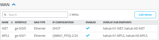
Edit a first WAN interface with the name “INET” as follows:
- Name=
INETthis indicates which Topology it’s going to use.- Endpoint1=
hahub-N0-INET - Endpoint2=
hahub-N1-INET
- Endpoint1=
Edit a second WAN interface with the name “MPLS” as follows:
- Name=
INETthis indicates which Topology it’s going to use.- Endpoint1=
hahub-N0-MPLS - Endpoint2=
hahub-N1-MPLS
- Endpoint1=
The result should look like the figure below:
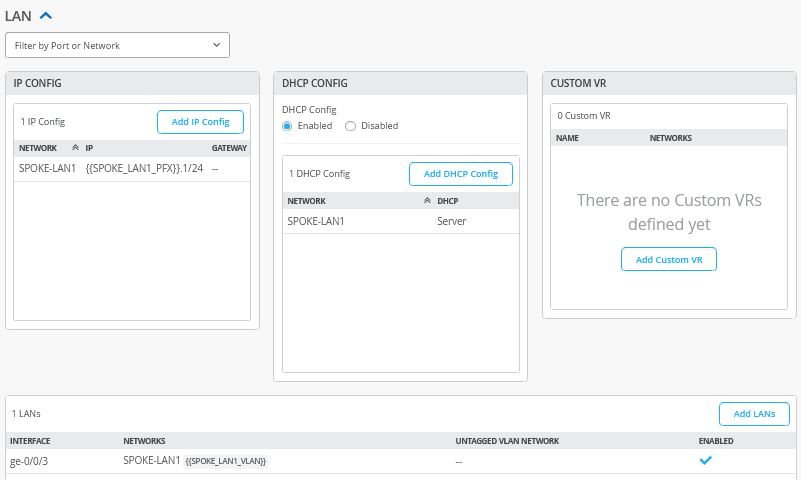
The LAN sections do not need to be changed and should still look like the figure below:
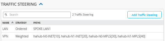
In the traffic steering section, we need to edit the end points of the “VPN” profile. Please apply the following configuration:
- Name=
VPN - Strategy=
Weighted - Paths
- Path1 Type=
Overlay: hahub-N0-INET - Path1 Cost=
10 - Path2 Type=
Overlay: hahub-N1-INET - Path2 Cost=
20 - Path3 Type=
Overlay: hahub-N0-MPLS - Path3 Cost=
30 - Path4 Type=
Overlay: hahub-N1-MPLS - Path4 Cost=
40
- Path1 Type=
The result should look like the figure below:
In application policies, we need to change the prior
HUB1-LAN1 and HUB2-LAN1 definitions to a
single HAHUB-LAN1 as indicated in the figure
below:
Save your results.
Create a WAN Edge Template for a High-Availability Spoke
Go to Organization -> WAN Edge Templates.
Should you choose to use the import option, click on Import Profile and import the below JSON as a file.
{
  "type": "spoke",
  "dhcpd_config": {
    "enabled": true,
    "SPOKE-LAN1": {
      "type": "local",
      "ip_start": "{{SPOKE_LAN1_PFX}}.10",
      "ip_end": "{{SPOKE_LAN1_PFX}}.250",
      "gateway": "{{SPOKE_LAN1_PFX}}.1",
      "dns_servers": [
        "8.8.8.8",
        "9.9.9.9"
      ],
      "options": {},
      "lease_time": 86400,
      "fixed_bindings": {}
    }
  },
  "ntpOverride": true,
  "dnsOverride": true,
  "service_policies": [
    {
      "name": "spoke-to-hub-dmz",
      "tenants": [
        "SPOKE-LAN1"
      ],
      "services": [
        "HAHUB-LAN1"
      ],
      "action": "allow",
      "idp": {
        "enabled": false
      },
      "path_preference": "VPN"
    },
    {
      "name": "hub-dmz-to-spoke",
      "tenants": [
        "HAHUB-LAN1"
      ],
      "services": [
        "SPOKE-LAN1"
      ],
      "action": "allow",
      "path_preference": "LAN",
      "idp": {
        "enabled": false
      }
    },
    {
      "name": "spoke-to-spoke-via-hub",
      "tenants": [
        "SPOKE-LAN1"
      ],
      "services": [
        "SPOKE-LAN1"
      ],
      "action": "allow",
      "idp": {
        "enabled": false
      },
      "local_routing": true
    },
    {
      "tenants": [
        "SPOKE-LAN1"
      ],
      "services": [
        "any"
      ],
      "action": "allow",
      "name": "internet-via-hub-cbo",
      "idp": {
        "enabled": false
      },
      "path_preference": "VPN"
    }
  ],
  "ip_configs": {
    "SPOKE-LAN1": {
      "type": "static",
      "ip": "{{SPOKE_LAN1_PFX}}.1",
      "netmask": "/24"
    }
  },
  "dns_servers": [
    "8.8.8.8",
    "9.9.9.9"
  ],
  "port_config": {
    "ge-0/0/0": {
      "name": "N0-INET",
      "usage": "wan",
      "aggregated": false,
      "redundant": false,
      "critical": false,
      "disabled": false,
      "wan_type": "broadband",
      "ip_config": {
        "type": "dhcp"
      },
      "disable_autoneg": false,
      "wan_source_nat": {
        "disabled": false
      },
      "vpn_paths": {
        "hahub-N0-INET.OrgOverlay": {
          "role": "spoke",
          "bfd_profile": "broadband"
        },
        "hahub-N1-INET.OrgOverlay": {
          "role": "spoke",
          "bfd_profile": "broadband"
        }
      }
    },
    "ge-1/0/0": {
      "name": "N1-INET",
      "usage": "wan",
      "aggregated": false,
      "redundant": false,
      "critical": false,
      "disabled": false,
      "wan_type": "broadband",
      "ip_config": {
        "type": "dhcp"
      },
      "disable_autoneg": false,
      "wan_source_nat": {
        "disabled": false
      },
      "vpn_paths": {
        "hahub-N0-INET.OrgOverlay": {
          "role": "spoke",
          "bfd_profile": "broadband",
          "key": 0
        },
        "hahub-N1-INET.OrgOverlay": {
          "role": "spoke",
          "bfd_profile": "broadband",
          "key": 1
        }
      }
    },
    "ge-0/0/1,ge-1/0/1": {
      "name": "HA-MPLS",
      "usage": "wan",
      "aggregated": false,
      "redundant": true,
      "reth_idx": 1,
      "reth_node": "node0",
      "critical": false,
      "disabled": false,
      "wan_type": "broadband",
      "ip_config": {
        "type": "static",
        "ip": "{{WAN1_PFX}}.2",
        "netmask": "/24",
        "gateway": "{{WAN1_PFX}}.1"
      },
      "disable_autoneg": false,
      "wan_source_nat": {
        "disabled": false
      },
      "vpn_paths": {
        "hahub-N0-MPLS.OrgOverlay": {
          "role": "spoke",
          "bfd_profile": "broadband",
          "key": 0
        },
        "hahub-N1-MPLS.OrgOverlay": {
          "role": "spoke",
          "bfd_profile": "broadband",
          "key": 1
        }
      }
    },
    "ge-0/0/3,ge-1/0/3": {
      "networks": [
        "SPOKE-LAN1"
      ],
      "usage": "lan",
      "aggregated": false,
      "redundant": true,
      "reth_idx": 3,
      "reth_node": "node0",
      "critical": false,
      "disabled": false
    }
  },
  "bgp_config": {},
  "routing_policies": {},
  "extra_routes": {},
  "path_preferences": {
    "LAN": {
      "strategy": "ordered",
      "paths": [
        {
          "type": "local",
          "networks": [
            "SPOKE-LAN1"
          ]
        }
      ]
    },
    "VPN": {
      "strategy": "weighted",
      "paths": [
        {
          "name": "hahub-N0-INET.OrgOverlay",
          "cost": 10,
          "type": "vpn"
        },
        {
          "name": "hahub-N1-INET.OrgOverlay",
          "cost": 20,
          "type": "vpn"
        },
        {
          "name": "hahub-N0-MPLS.OrgOverlay",
          "cost": 30,
          "type": "vpn"
        },
        {
          "name": "hahub-N1-MPLS.OrgOverlay",
          "cost": 40,
          "type": "vpn"
        }
      ]
    }
  },
  "ospf_areas": {},
  "vrf_instances": {},
  "tunnel_configs": {},
  "oob_ip_config": {
    "type": "dhcp",
    "node1": {
      "type": "dhcp"
    }
  },
  "tunnel_provider_options": {
    "jse": {},
    "zscaler": {}
  },
  "ospf_config": {
    "enabled": false,
    "areas": {}
  },
  "name": "ha-spoke"
}
Should you decide to configure everything manually in the Juniper Mist portal, then use the following steps.
We recommend you clone the existing “single-spoke” template and name the new template “ha-spoke”. Then make the following changes as the WAN and LAN interfaces change with the high-availability configuration.
Delete all prior WAN interfaces and add the following three new WAN interfaces.
Configure a first WAN interface for Node0 as follows:
- Name=
N0-INETthis indicates which topology and node it’s going to use. - WAN Type=
Ethernet - Interface=
ge-0/0/0as all interfaces starting withge-0are on node0. - IP Configuration=
DHCP - Source NAT=
Interface - Overlay Hub Endpoints
- Endpoint1=
hahub-N0-INET - BFD Profile1=
Broadband - Endpoint2=
hahub-N1-INET - BFD Profile2=
Broadband
- Endpoint1=
Then configure a first WAN interface for Node1 as follows:
- Name=
N1-INETthis indicates which Topology and Node it’s going to use. - WAN Type=
Ethernet - Interface=
ge-1/0/0as all interfaces starting withge-1are on node1. - IP Configuration=
DHCP - Source NAT=
Interface - Overlay Hub Endpoints
- Endpoint1=
hahub-N0-INET - BFD Profile1=
Broadband - Endpoint2=
hahub-N1-INET - BFD Profile2=
Broadband
- Endpoint1=
Then configure the third and redundant WAN interface for the MPLS path for Node0 and Node1 as follows:
- Name=
HA-MPLSthis indicates which topology and node it’s going to use. - WAN Type=
Ethernet - Interface=
ge-0/0/1,ge-1/0/1- Redundant=
Checked/Enabled - Redundant Index=1 (this is not required for an SSR, but we add it for compatibility)
- Primary Node=
node0
- Redundant=
- IP Configuration=
Static -
IP Address={{WAN1_PFX}}.2 -
Prefix Length=24 -
Gateway={{WAN1_PFX}}.1 - Source NAT=
Interface - Overlay Hub Endpoints
- Endpoint1=
hahub-N0-MPLS - BFD Profile1=
Broadband - Endpoint2=
hahub-N1-MPLS - BFD Profile2=
Broadband
- Endpoint1=
The result should look like the figure below:
In the LAN section, the IP config and DHCP config stay the same inherited from the previous templates. The LAN interface itself needs to be edited to support the redundant configuration. Please change the existing configuration so that you have the following:
- Interface=
ge-0/0/3,ge-1/0/3 - Redundant=Checked/Enabled
- Redundant Index=3 (this is not required for an SSR, but we add it for compatibility)
- Primary Node=node0
- Networks=
SPOKE-LAN1 - Untagged VLAN=
None
The result should look like the figure below:
Traffic steering and application profiles should be inherited from the already existing “single-spoke” template, so they do not need to be changed. They should look like the figure below:
Save your results.
Remaining Tasks for This Lab
First you need to assign the new spoke templates to their sites.
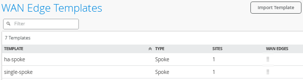
Go to Organization -> WAN Edge Templates -> “single-spoke” template and click on Assign to Sites. Then, assign spoke1-site to this template.
Go to Organization -> WAN Edge Templates -> “ha-spoke” template and click on Assign to Sites. Then, assign spoke2-site to this template.
The result should look like the figure below:
If you have the hub and spoke devices in use from previous labs, go to the inventory and release them. This will bring them back into factory state.
Here, we describe how to build a cluster during the onboarding—assuming all devices are in a factory default state.
Go to Organization -> Inventory and select WAN Edges and click Claim WAN Edges. Then, do the following:
- Assign claimed WAN Edge to
site=
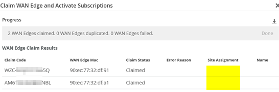
Unchecked/Disabled. - Enter the claim codes for the two devices.
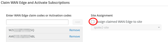
This will claim the two devices without assigning them to a site.
Select the two devices and click on Assign To Site from the More menu.
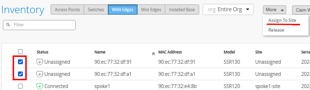
Now configure the following:
- Assign the two selected WAN edges to
site=
spoke2-site - Create Cluster=
Checked/Enabled - Select a device to act as node0 = select that as required
- Manage Configuration with Mist=
Enabled(automatically)
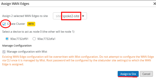
This will commit the needed cluster configuration for the HA spoke.
The hahub follows a similar process that we do not repeat here. You will have to claim two other devices and then use the new site “hahub-site”.
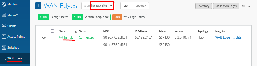
After all clusters have been brought up (and you gave them a name) the inventory should look similar to the figure below:

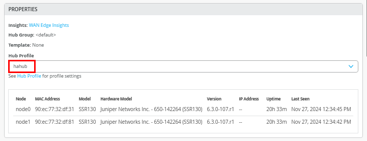
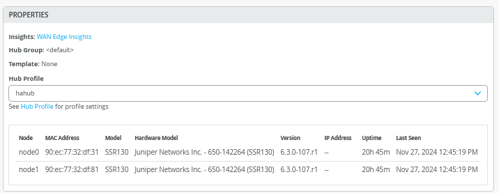
Do not forget to assign the hub profile as the last step. Go to WAN Edges and select site “hahub-site” and select the cluster device.
Then, under properties, configure the following:
- Hub Profile=
hahub
Test Your Network Configuration
We are now ready to test our configuration.
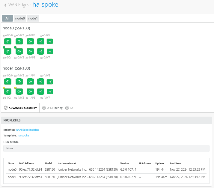
Go to WAN Edges -> site=hahub-site and click “hahub”.
.png)
Review the device information.
Review the properties information to determine which devices are Node0 and Node1.
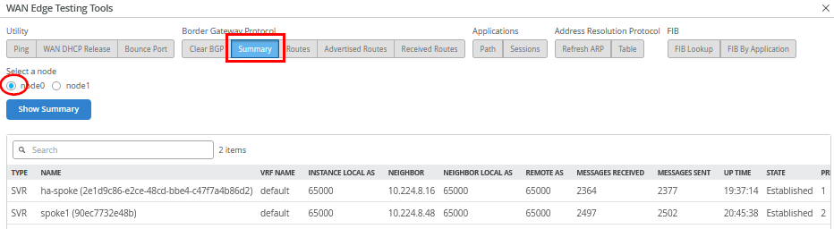
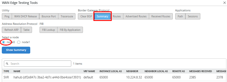
When you use Utilities -> Testing Tools and review the BGP neighbor summary, you will see two spokes (redundant and non-redundant) connected and exchanging routes.
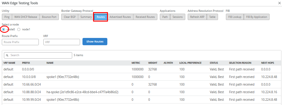
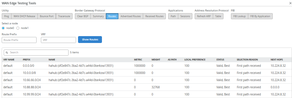
Also, review the routes distributed in the VPN.
Go to WAN Edges -> site=spoke2-site and click on “ha-spoke”.
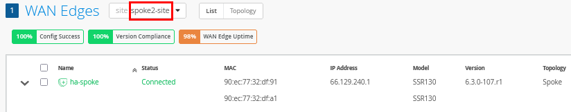
Review the device and properties information.
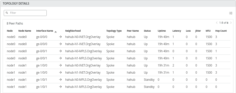
Review the topology details with the eight tunnels connecting this spoke to the HAHub. Two are down as the MPLS interface is configured for active-passive VRRP redundancy.
When you use Utilities -> Testing Tools and review the BGP neighbor summary, you will only see hahub connected and exchanging routes.
Also review the routes distributed in the VPN.
We shall now continue our testing on the clients attached to the
spokes. We connect to the desktop2 VM with IP address
10.88.88.88 attached to the redundant spoke2.
# try to reach the local WAN-Router interface desktop2 VM is attached to
root@desktop2:~# ping -c3 10.88.88.1
PING 10.88.88.1 (10.88.88.1) 56(84) bytes of data.
64 bytes from 10.88.88.1: icmp_seq=1 ttl=128 time=0.320 ms
64 bytes from 10.88.88.1: icmp_seq=2 ttl=128 time=0.287 ms
64 bytes from 10.88.88.1: icmp_seq=3 ttl=128 time=0.241 ms
#
# try to reach the client desktop1 VM attached to spoke1
# this causes relay on the hahub for this traffic
root@desktop2:~# ping -c3 10.99.99.99
PING 10.99.99.99 (10.99.99.99) 56(84) bytes of data.
64 bytes from 10.99.99.99: icmp_seq=1 ttl=56 time=7.30 ms
64 bytes from 10.99.99.99: icmp_seq=2 ttl=56 time=1.75 ms
64 bytes from 10.99.99.99: icmp_seq=3 ttl=56 time=1.66 ms
#
# try to reach the client desktop4 VM attached to hahub
root@desktop2:~# ping -c3 10.66.66.66
PING 10.66.66.66 (10.66.66.66) 56(84) bytes of data.
64 bytes from 10.66.66.66: icmp_seq=1 ttl=59 time=3.39 ms
64 bytes from 10.66.66.66: icmp_seq=2 ttl=59 time=1.19 ms
64 bytes from 10.66.66.66: icmp_seq=3 ttl=59 time=0.952 ms
#
# let a continued ping to the internet run
# in our case all traffic is sent to hub for central breakout
root@desktop2:~# ping 8.8.8.8
PING 8.8.8.8 (8.8.8.8) 56(84) bytes of data.
64 bytes from 8.8.8.8: icmp_seq=1 ttl=46 time=7.93 ms
64 bytes from 8.8.8.8: icmp_seq=2 ttl=46 time=3.90 ms
64 bytes from 8.8.8.8: icmp_seq=3 ttl=46 time=3.98 ms
.
.
Use Utilities -> Testing Tools to review the
application sessions with Application Name=any . Due
to the reverse flow, we see that the traffic is received from
Hub1’s Internet public IP address
192.168.129.191.
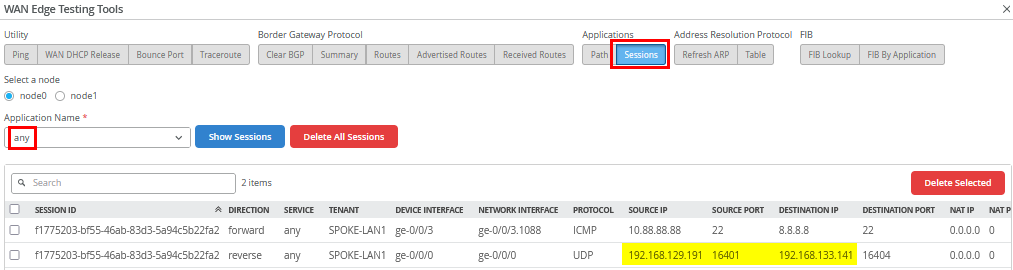
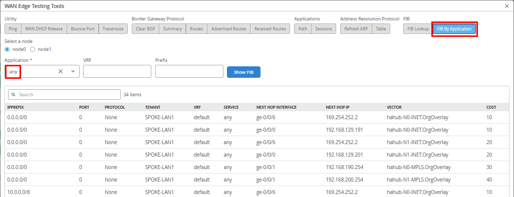
Also review the FIB on spoke2.
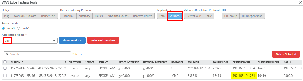
Go to WAN Edges -> site=hahub-site and
select “hahub”. Then, use Utilities ->
Testing Tools and review the application sessions with
Application Name=any again. Here, you can see the
reverse flow ICMP responses to the source NATed interface
ge-0/0/0 where we forwarded our traffic to.
The remaining testing is done with the clients attached to the
redundant hub. We connect to the desktop4 VM with IP address
10.66.66.66 attached to hahub.
# try to reach the client desktop1 VM attached to singe spoke1
root@desktop4:~# ping -c3 10.99.99.99
PING 10.99.99.99 (10.99.99.99) 56(84) bytes of data.
64 bytes from 10.99.99.99: icmp_seq=1 ttl=59 time=4.98 ms
64 bytes from 10.99.99.99: icmp_seq=2 ttl=59 time=1.07 ms
64 bytes from 10.99.99.99: icmp_seq=3 ttl=59 time=1.03 ms
#
# try to reach the client desktop2 VM attached to redundant spoke2
root@desktop4:~# ping -c3 10.88.88.88
PING 10.88.88.88 (10.88.88.88) 56(84) bytes of data.
64 bytes from 10.88.88.88: icmp_seq=1 ttl=59 time=5.49 ms
64 bytes from 10.88.88.88: icmp_seq=2 ttl=59 time=1.15 ms
64 bytes from 10.88.88.88: icmp_seq=3 ttl=59 time=1.06 ms
#
# try services on the internet using the local breakout on the hub
root@desktop4:~# ping -c3 8.8.8.8
PING 8.8.8.8 (8.8.8.8) 56(84) bytes of data.
64 bytes from 8.8.8.8: icmp_seq=1 ttl=109 time=3.10 ms
64 bytes from 8.8.8.8: icmp_seq=2 ttl=109 time=2.67 ms
64 bytes from 8.8.8.8: icmp_seq=3 ttl=109 time=2.68 ms
Your lab topology should be up and running now and you can explore failover testing as you like.
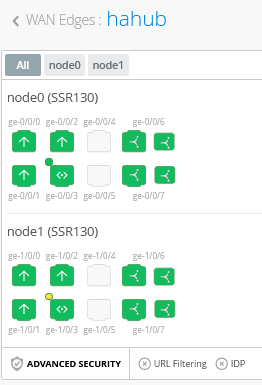
The best way to figure out which node is currently active is to look at the LAN interfaces that we’ve configured for redundancy on our high-availability spokes and hubs. These tasks for JVD testing were performed but not shared here in this document.
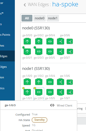
In the example below, the interface ge-0/0/3 on
Node0 is in an active HA state.
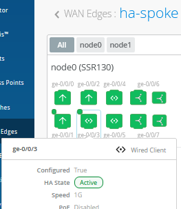
While interface ge-1/0/3 on Node1 is in a standby
HA state.