
Appendix: Layer 3 Exit With OSPF Routing Protocol
When doing any VLAN or VRF creation with campus fabric, use the following best practices:
All overlay VLANs should be created only through a switch template and then imported into the campus fabric configuration. Creating overlay VLANs in other places, such as directly on a switch, can eventually lead to inconsistencies that make troubleshooting more difficult.
Two additional transport VLANs must be created for each VRF. Refer to the guidance below for further recommendations.
ADo not create VRFs manually, either in the switch template or directly on a switch. If required, the fabric will create them automatically, so it is important not to interfere with this process.
Port profiles are also best created through switch templates to ensure that any changes remain synchronized across all switches in the fabric.
Before starting, a design must be created to determine how the routing protocol exchange will be implemented, how the point-to-point links will be configured, and how VLAN assignments will be distributed to indirectly identify the VRF. Even if a VRF is already created elsewhere in the fabric, such as on an access switch in an IP Clos design, the system will automatically recreate it on all service block functions when a Layer 3 exit is configured.
For each WAN router connection, an additional transport VLAN must be added to the VRF and then configured as a custom VRF on the service block function. Because this design uses two WAN routers, each VRF requires two additional transport VLANs on the service block function to establish OSPF peering. When using transport VLANs, they must not be included in the overlay network definition of the EVPN fabric. These VLANs can be added to the switch template as long as they are not selected in the campus fabric configuration dialogue when defining networks. As an alternative, they can be created only on the service block function where they are locally required. All transport VLANs should be created with only a network name and a VLAN ID.
When defining point-to-point links, choose IP addresses from a range that does not overlap with the range used by the fabric, which by default is 10.255.240.0/20. A /31 subnet mask is commonly used, assigning the even IP address to the WAN router and the odd IP address to the fabric as a convention.
The system requires a VLAN to be defined for each point-to-point link over a physical connection. This approach allows multiple VRFs to be multiplexed over a single uplink cable, with the VLAN internally referencing the associated VRF.
When using OSPF, each VRF and service block function must have its own OSPF router ID to exchange routes with the redundant WAN routers. On the WAN routers, a global OSPF router ID can be used, as shown in this example. Do not confuse these with the EVPN fabric router IDs displayed in the Juniper Mist portal for each EVPN fabric switch. Those router IDs are controlled by the EVPN fabric and cannot be modified in this configuration
.
The use of individual OSPF router IDs on the EVPN fabric is necessary because a single global router ID shared across VRFs can lead to missed route updates from the WAN router to certain VRFs. When a global router ID is used on the EVPN fabric, the WAN router may assume that it has already sent the route update to the OSPF neighbor, the fabric, and may therefore skip sending updates over other links where different VRFs of the EVPN fabric are connected. Assigning a unique OSPF router ID to each VRF and service block function ensures that route updates are properly exchanged across all established point-to-point links.
To provide unique router IDs for OSPF neighbor relationships toward the WAN router, the Juniper Mist cloud uses the loopback per-VRF IPv4 subnet pool defined in the campus fabric configuration dialogue. This pool is typically used to generate individual IP addresses for DHCP relay. For OSPF, the same IP addresses assigned as lo0.x loopback interfaces are also used as the individual OSPF router IDs.
The default pool range is 172.16.192.0/24. You can review what your service block function will use as an OSPF Router ID in the Juniper Mist portal on the statistics pane. Please note that lo0.0 is always the EVPN router ID managed by a different pool and cannot be modified.
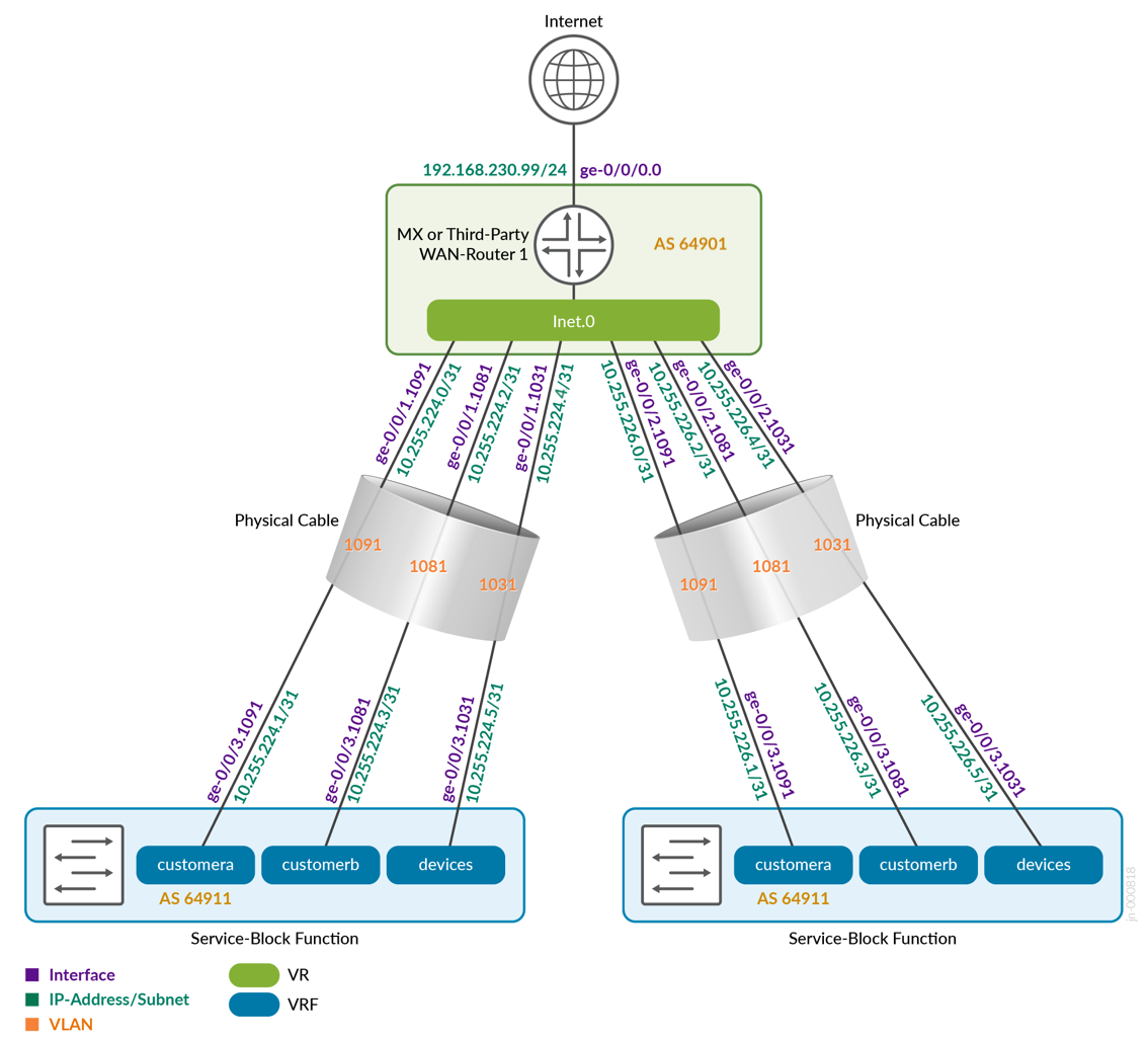
The picture below shows how the two service block functions of the fabric connect to the first WAN router.
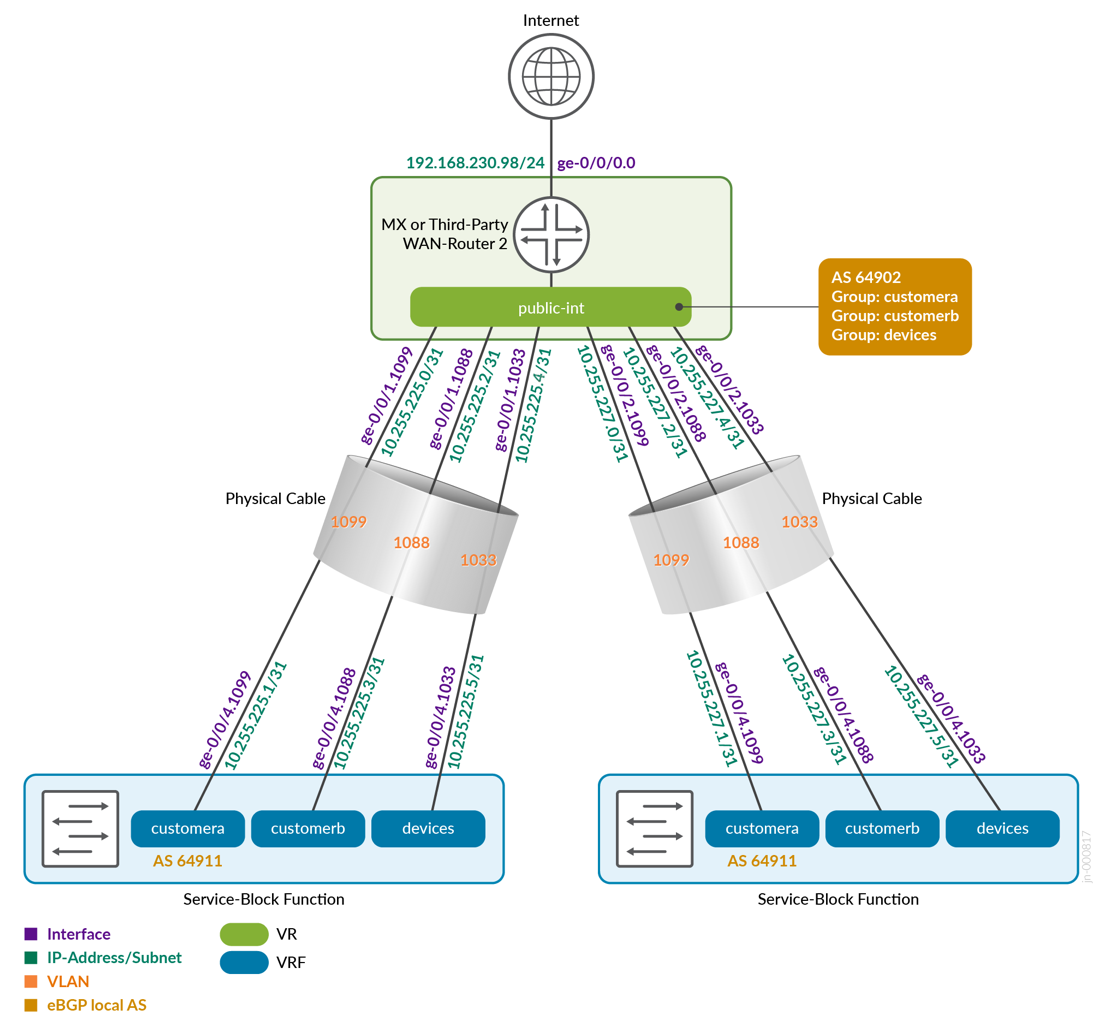
The picture below shows how the two service block functions of the fabric connect to the second WAN router. Notice that we now use the second block of VLANs from each VRF.
Below is the full configuration table between core1 and core2 as the service block function and the two WAN routers. OSPF area 0.0.0.0 was used among all peers.
| Switch | VRF | OSPF Router ID | Core P2P IP | Core IF | WAN Router | OSPF Router ID | WAN Router P2P IP | WAN Router IF | VLAN ID | |
|---|---|---|---|---|---|---|---|---|---|---|
| core1 | customera | Mist managed | 10.255.224.1/31 | ge-0/0/3.101 | wanrouter1 | 10.23.42.1 (global) | 10.255.224.0/31 | ge-0/0/1.101 | 101 | |
| core1 | customerb | Mist managed | 10.255.224.3/31 | ge-0/0/3.102 | wanrouter1 | 10.23.42.1 (global) | 10.255.224.2/31 | ge-0/0/1.102 | 102 | |
| core1 | devices | Mist managed | 10.255.224.5/31 | ge-0/0/3.103 | wanrouter1 | 10.23.42.1 (global) | 10.255.224.4/31 | ge-0/0/1.103 | 103 | |
| core1 | customera | Mist managed | 10.255.225.1/31 | ge-0/0/4.201 | wanrouter2 | 10.23.42.2 (global) | 10.255.225.0/31 | ge-0/0/1.201 | 201 | |
| core1 | customerb | Mist managed | 10.255.225.3/31 | ge-0/0/4.202 | wanrouter2 | 10.23.42.2 (global) | 10.255.225.2/31 | ge-0/0/1.202 | 202 | |
| core1 | devices | Mist managed | 10.255.225.5/31 | ge-0/0/4.203 | wanrouter2 | 10.23.42.2 (global) | 10.255.225.4/31 | ge-0/0/1.203 | 203 | |
| core2 | customera | Mist managed | 10.255.226.1/31 | ge-0/0/3.101 | wanrouter1 | 10.23.42.1 (global) | 10.255.226.0/31 | ge-0/0/2.101 | 101 | |
| core2 | customerb | Mist managed | 10.255.226.3/31 | ge-0/0/3.102 | wanrouter1 | 10.23.42.1 (global) | 10.255.226.2/31 | ge-0/0/2.102 | 102 | |
| core2 | devices | Mist managed | 10.255.226.5/31 | ge-0/0/3.103 | wanrouter1 | 10.23.42.1 (global) | 10.255.226.4/31 | ge-0/0/2.103 | 103 | |
| core2 | customera | Mist managed | 10.255.227.1/31 | ge-0/0/4.201 | wanrouter2 | 10.23.42.2 (global) | 10.255.227.0/31 | ge-0/0/2.201 | 201 | |
| core2 | customerb | Mist managed | 10.255.227.3/31 | ge-0/0/4.202 | wanrouter2 | 10.23.42.2 (global) | 10.255.227.2/31 | ge-0/0/2.202 | 202 | |
| core2 | devices | Mist managed | 10.255.227.5/31 | ge-0/0/4.203 | wanrouter2 | 10.23.42.2 (global) | 10.255.227.4/31 | ge-0/0/2.203 | 203 | |
Fabric Creation
Below, we are sharing the exported version of the switch template used in this fabric. This will allow you to review our setup when importing. The two transport VLANs for each VRF were created on the service block function itself.
{
  "additional_config_cmds": [],
  "networks": {
    "vlan1099": {
      "vlan_id": 1099,
      "subnet": "10.99.99.0/24"
    },
    "vlan1088": {
      "vlan_id": 1088,
      "subnet": "10.88.88.0/24"
    },
    "vlan1033": {
      "vlan_id": 1033,
      "subnet": "10.33.33.0/24"
    },
    "vlan1091": {
      "vlan_id": 1091,
      "subnet": "10.99.91.0/24"
    },
    "vlan1081": {
      "vlan_id": 1081,
      "subnet": "10.88.81.0/24"
    },
    "vlan1031": {
      "vlan_id": 1031,
      "subnet": "10.33.31.0/24"
    }
  },
  "port_usages": {
    "vlan1099": {
      "mode": "access",
      "disabled": false,
      "port_network": "vlan1099",
      "voip_network": null,
      "stp_edge": false,
      "mac_auth_protocol": null,
      "all_networks": false,
      "networks": null,
      "port_auth": null,
      "enable_mac_auth": null,
      "mac_auth_only": null,
      "guest_network": null,
      "bypass_auth_when_server_down": null,
      "speed": "auto",
      "duplex": "auto",
      "mac_limit": 0,
      "persist_mac": false,
      "poe_disabled": false,
      "enable_qos": false,
      "storm_control": {},
      "mtu": null,
      "description": "",
      "disable_autoneg": false
    },
    "vlan1088": {
      "mode": "access",
      "disabled": false,
      "port_network": "vlan1088",
      "voip_network": null,
      "stp_edge": false,
      "mac_auth_protocol": null,
      "all_networks": false,
      "networks": null,
      "port_auth": null,
      "enable_mac_auth": null,
      "mac_auth_only": null,
      "guest_network": null,
      "bypass_auth_when_server_down": null,
      "speed": "auto",
      "duplex": "auto",
      "mac_limit": 0,
      "persist_mac": false,
      "poe_disabled": false,
      "enable_qos": false,
      "storm_control": {},
      "mtu": null,
      "description": "",
      "disable_autoneg": false
    },
    "dynamic": {
      "mode": "dynamic",
      "reset_default_when": "link_down",
      "rules": []
    }
  },
  "switch_matching": {
    "enable": true,
    "rules": []
  },
  "switch_mgmt": {
    "config_revert_timer": 10,
    "root_password": "juniper123",
    "protect_re": {
      "enabled": false
    },
    "tacacs": {
      "enabled": false
    }
  },
  "mist_nac": {
    "enabled": true,
    "network": null
  },
  "radius_config": {
    "auth_servers": [],
    "acct_servers": [],
    "auth_servers_timeout": 5,
    "auth_servers_retries": 3,
    "fast_dot1x_timers": false,
    "acct_interim_interval": 0,
    "auth_server_selection": "ordered",
    "coa_enabled": false,
    "coa_port": ""
  },
  "vrf_config": {
    "enabled": false
  },
  "remote_syslog": {
    "enabled": false
  },
  "snmp_config": {
    "enabled": false
  },
  "dhcp_snooping": {
    "enabled": false
  },
  "dns_servers": [],
  "dns_suffix": [],
  "ntp_servers": [],
  "acl_policies": [],
  "port_mirroring": {},
  "name": "campus-fabric"
}
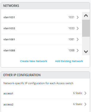
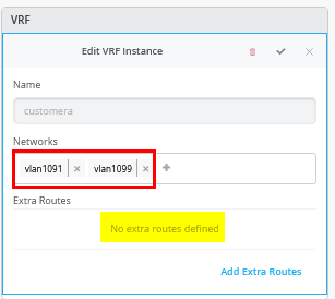
Inside the campus fabric configuration dialogue there is a page called “Configure Networks”. This is where you will import your 3*2=6 VLANs from the switch template and the result in our case will look like the image below.
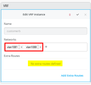
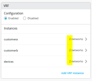
The next step is to create all three VRFs and attach two of the networks to each like that shown below.
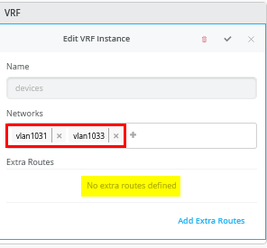
Then, go to each VRF and delete all manual routes you may have. Make sure each VRF has a minimum of two VLANs attached as those are used to identify the VRF later.
This is for the second VRF.
This is for the third VRF.
Core1 Switch Configuration
In our case, the service block function is virtual and colocated on the core switch, hence we must configure the two core switches. Below is a description of what you need to configure on the core1 switch:
# create the following transport networks either in a switch-template or locally on each service switch
# create network name:trans101 with VLAN-ID:101
# create network name:trans102 with VLAN-ID:102
# create network name:trans103 with VLAN-ID:103
# create network name:trans201 with VLAN-ID:201
# create network name:trans202 with VLAN-ID:202
# create network name:trans203 with VLAN-ID:203
#
# configure the Additional IP-Subnet 10.255.224.1 255.255.255.254 to Network/VLAN:trans101
# configure the Additional IP-Subnet 10.255.224.3 255.255.255.254 to Network/VLAN:trans102
# configure the Additional IP-Subnet 10.255.224.5 255.255.255.254 to Network/VLAN:trans103
# Then bind these 3 Network/VLANs to Port Interface ge-0/0/3 as L3-Sub-Interfaces with MTU=9018
#
# configure the Additional IP-Subnet 10.255.225.1 255.255.255.254 to Network/VLAN:trans201
# configure the Additional IP-Subnet 10.255.225.3 255.255.255.254 to Network/VLAN:trans202
# configure the Additional IP-Subnet 10.255.225.5 255.255.255.254 to Network/VLAN:trans203
# Then bind these 3 Network/VLANs to Port Interface ge-0/0/4 as L3-Sub-Interfaces with MTU=9018
#
# Go to the Routing Policy-Section
# Create an Export policy called 'export-vrfs'
# Add to this export Policy the following Networks as:
# - Add Term w. Name=exclude-default  Prefix=0.0.0.0/0  Protocol=None  Then=Reject
# - Add Term w. Name=fabric-all-no-hosts  Prefix=0.0.0.0/0-30  Protocol=None  Then=Accept
# - Add Term w. Name=overlaylo0 Prefix=172.16.192.0/24-32  Protocol=None  Then=Accept
#
# Create an Import policy called 'import-default'
# - Name=default  Prefix=0.0.0.0/0  Protocol=OSPF  Action=Accept
#
# Go back to the OSPF Areas-Section
# ADD a new OSPF Area='0'  Type='default'  Caution! DO NOT include/select Loopback!!!
#
# In that Area configure the following OSPF Networks:
# Network (VLAN)=trans101   Interface Type='p2p'  Authentication='none'  BFD Interval='1000'
# Network (VLAN)=trans102   Interface Type='p2p'  Authentication='none'  BFD Interval='1000'
# Network (VLAN)=trans103   Interface Type='p2p'  Authentication='none'  BFD Interval='1000'
# Network (VLAN)=trans201   Interface Type='p2p'  Authentication='none'  BFD Interval='1000'
# Network (VLAN)=trans202   Interface Type='p2p'  Authentication='none'  BFD Interval='1000'
# Network (VLAN)=trans203   Interface Type='p2p'  Authentication='none'  BFD Interval='1000'
#
# OSPF Configration='enabled'
#
# Set the Export policy to 'export-vrfs'
# Set the Import policy to 'import-default'
#
# In the Areas section add your Area='0' to OSPF
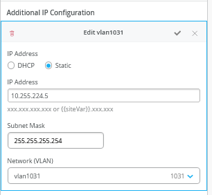
Below are several screenshots that illustrate key parts of the configuration described above. The first screenshots show the additional transport VLANs that were defined locally. In the example below, only the first two of the six transport VLANs are displayed. Note that overlay VLANs, such as VLAN1099, are inherited from the switch template.
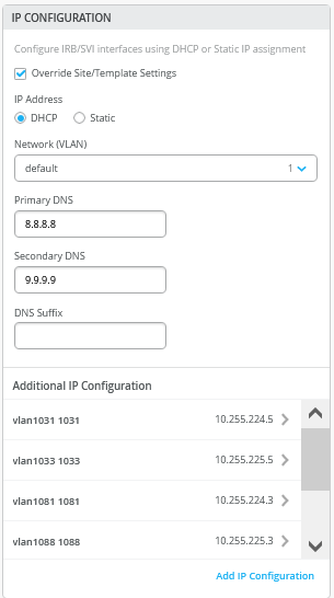
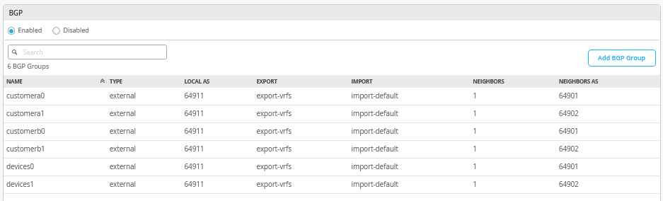
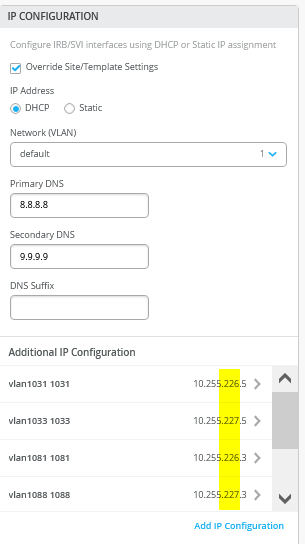
Begin with the additional IP configuration. Note that the same VLAN is used between the two service block functions, but each uses different point-to-point IP addresses. Also remember that the transport VLAN serves as a reference to the corresponding VRF when defining the BGP peering.
Here is an example of one of the six transport VLANs to be defined.
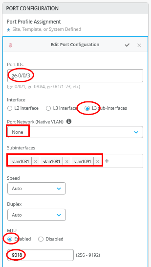
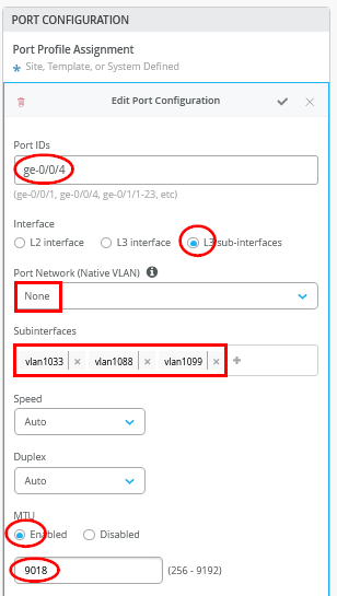
In the port configuration, it is essential to use Layer 3 subinterfaces and associate them with the first set of subinterfaces that were defined.
In the second port configuration toward the other WAN router, the remaining subinterfaces are associated accordingly.
The next step is to add all transport VLANs to each VRF as custom networks, so they are recognized within the VRF. As shown, each VRF ultimately contains four networks: two used in the overlay and two additional transport VLANs added at the service block function.
An individual custom VRF would look like the example shown below.
When overlay VLANs are added or removed later through a switch template and the campus fabric configuration interface, the same changes must also be made in the custom VRF on the service block function. These VLANs are not added automatically, so if this step is overlooked they will not be advertised to the WAN router.
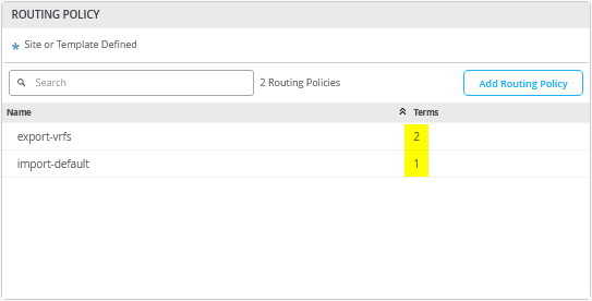
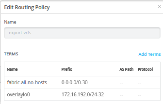
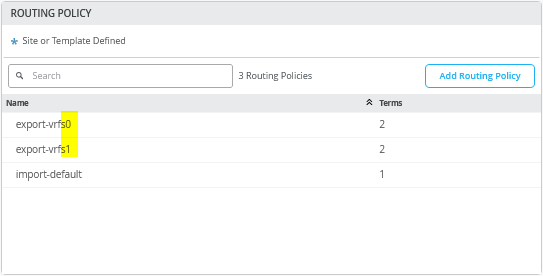
The next step is to define two routing policies.

In this example, the export route policies include the following terms:
- Term=
exclude-defaultprevents the default route learned from the first WAN router from being exported to the second WAN router, and vice versa. - Term=
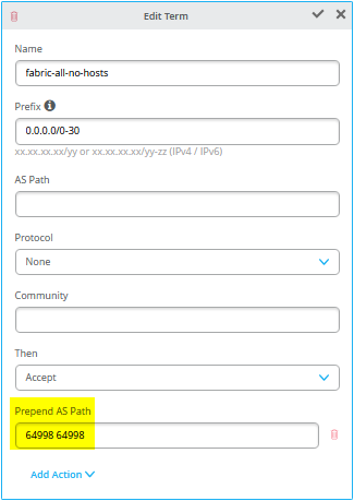
fabric-all-no-hostsautomatically exports all routes from the fabric across all configured VRFs and their associated VLANs. However, point-to-point links and single-host routes are excluded. This is achieved by using the prefix 0.0.0.0/0-30, where specifying 0-30 in Junos OS represents an “orlonger” prefix range up to /30. - Term=
overlaylo0exports the overlay loopback IP addresses used for DHCP relay down to the host prefix level, since they are typically assigned individually to lo0.x interfaces. To accomplish this, the prefix 172.16.192.0/24-32 is used, allowing the range to extend down to host-level prefixes, which is not done in the previous statement.
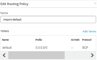
The import policy usually just imports the default route from the WAN router.
The next step is to create the OSPF area and assign the six transport VLANs to it.
Here is a review of one of the configured VLANs.
Finally, enable OSPF, map the two filters, and add the area you just defined.
Core2 Switch Configuration
Below is a description of what you also need to configure on the core2 switch:
# create the following transport networks either in a switch-template or locally on each service switch
# create network name:trans101 with VLAN-ID:101
# create network name:trans102 with VLAN-ID:102
# create network name:trans103 with VLAN-ID:103
# create network name:trans201 with VLAN-ID:201
# create network name:trans202 with VLAN-ID:202
# create network name:trans203 with VLAN-ID:203
#
# configure the Additional IP-Subnet 10.255.226.1 255.255.255.254 to Network/VLAN:trans101
# configure the Additional IP-Subnet 10.255.226.3 255.255.255.254 to Network/VLAN:trans102
# configure the Additional IP-Subnet 10.255.226.5 255.255.255.254 to Network/VLAN:trans103
# Then bind these 3 Network/VLANs to Port Interface ge-0/0/3 as L3-Sub-Interfaces with MTU=9018
#
# configure the Additional IP-Subnet 10.255.227.1 255.255.255.254 to Network/VLAN:trans201
# configure the Additional IP-Subnet 10.255.227.3 255.255.255.254 to Network/VLAN:trans202
# configure the Additional IP-Subnet 10.255.227.5 255.255.255.254 to Network/VLAN:trans203
# Then bind these 3 Network/VLANs to Port Interface ge-0/0/4 as L3-Sub-Interfaces with MTU=9018
#
# Go to the Routing Policy-Section
# Create an Export policy called 'export-vrfs'
# Add to this export Policy the following Networks as:
# - Add Term w. Name=exclude-default  Prefix=0.0.0.0/0  Protocol=None  Then=Reject
# - Add Term w. Name=fabric-all-no-hosts  Prefix=0.0.0.0/0-30  Protocol=None  Then=Accept
# - Add Term w. Name=overlaylo0 Prefix=172.16.192.0/24-32  Protocol=None  Then=Accept
#
# Create an Import policy called 'import-default'
# - Name=default  Prefix=0.0.0.0/0  Protocol=OSPF  Action=Accept
#
# Go back to the OSPF Areas-Section
# ADD a new OSPF Area='0'  Type='default'  Caution! DO NOT include Loopback!!!
#
# In that Area configure the following OSPF Networks:
# Network (VLAN)=trans101   Interface Type='p2p'  Authentication='none'  BFD Interval='1000'
# Network (VLAN)=trans102   Interface Type='p2p'  Authentication='none'  BFD Interval='1000'
# Network (VLAN)=trans103   Interface Type='p2p'  Authentication='none'  BFD Interval='1000'
# Network (VLAN)=trans201   Interface Type='p2p'  Authentication='none'  BFD Interval='1000'
# Network (VLAN)=trans202   Interface Type='p2p'  Authentication='none'  BFD Interval='1000'
# Network (VLAN)=trans203   Interface Type='p2p'  Authentication='none'  BFD Interval='1000'
#
# OSPF Configration='enabled'
#
# Set the Export policy to 'export-vrfs'
# Set the Import policy to 'import-default'
#
# In the Areas section add your Area='0' to OSPF
On core2, only the local IP addresses used for the peering subnets differ from those configured on core1, which were defined earlier.

Juniper MX as WAN Router
An OSPF example using an SRX Series Firewall is not included here. If you decide to implement this, ensure that different metrics are used so that traffic remains directed to a specific firewall unless a failure occurs. Since the traffic is stateful, it should not be distributed randomly across WAN routers that advertise identical metrics. When using BGP, this behavior can be controlled through AS-path prepending as described in the chapter Juniper SRX Series Firewall as WAN Router.
Below is the configuration of the point-to-point interfaces, the OSPF config and import and export routing policies. You may need to add default routes and interfaces to complete the configuration. We start with the first WAN router:
set system host-name wanrouter1
#
delete interfaces ge-0/0/1
set interfaces ge-0/0/1 flexible-vlan-tagging
set interfaces ge-0/0/1 mtu 9018
set interfaces ge-0/0/1 unit 101 description trans101
set interfaces ge-0/0/1 unit 101 vlan-id 101
set interfaces ge-0/0/1 unit 101 family inet address 10.255.224.0/31
set interfaces ge-0/0/1 unit 102 description trans102
set interfaces ge-0/0/1 unit 102 vlan-id 102
set interfaces ge-0/0/1 unit 102 family inet address 10.255.224.2/31
set interfaces ge-0/0/1 unit 103 description trans103
set interfaces ge-0/0/1 unit 103 vlan-id 103
set interfaces ge-0/0/1 unit 103 family inet address 10.255.224.4/31
#
delete interfaces ge-0/0/2
set interfaces ge-0/0/2 flexible-vlan-tagging
set interfaces ge-0/0/2 mtu 9018
set interfaces ge-0/0/2 unit 101 description trans101
set interfaces ge-0/0/2 unit 101 vlan-id 101
set interfaces ge-0/0/2 unit 101 family inet address 10.255.226.0/31
set interfaces ge-0/0/2 unit 102 description trans102
set interfaces ge-0/0/2 unit 102 vlan-id 102
set interfaces ge-0/0/2 unit 102 family inet address 10.255.226.2/31
set interfaces ge-0/0/2 unit 103 description trans103
set interfaces ge-0/0/2 unit 103 vlan-id 103
set interfaces ge-0/0/2 unit 103 family inet address 10.255.226.4/31
#
# needed in and export policy
delete policy-options policy-statement fabric
set policy-options policy-statement fabric term 1 from protocol ospf
set policy-options policy-statement fabric term 1 from route-filter 0.0.0.0/0 exact
set policy-options policy-statement fabric term 1 then reject
set policy-options policy-statement fabric term 2 from protocol ospf
set policy-options policy-statement fabric term 2 from route-filter 0.0.0.0/0 orlonger
set policy-options policy-statement fabric term 2 then accept
set policy-options policy-statement fabric term 3 then reject
#
delete policy-options policy-statement internet
set policy-options policy-statement internet term 1 from protocol static
set policy-options policy-statement internet term 1 from route-filter 0.0.0.0/0 exact
set policy-options policy-statement internet term 1 then external type 1
set policy-options policy-statement internet term 1 then accept
set policy-options policy-statement internet term 2 then reject
#
delete protocols ospf
set routing-options router-id 10.23.42.1
set protocols ospf area 0 interface ge-0/0/1.101 interface-type p2p
set protocols ospf area 0 interface ge-0/0/1.101 bfd-liveness-detection minimum-interval 1000
set protocols ospf area 0 interface ge-0/0/1.101 bfd-liveness-detection multiplier 3
set protocols ospf area 0 interface ge-0/0/1.102 interface-type p2p
set protocols ospf area 0 interface ge-0/0/1.102 bfd-liveness-detection minimum-interval 1000
set protocols ospf area 0 interface ge-0/0/1.102 bfd-liveness-detection multiplier 3
set protocols ospf area 0 interface ge-0/0/1.103 interface-type p2p
set protocols ospf area 0 interface ge-0/0/1.103 bfd-liveness-detection minimum-interval 1000
set protocols ospf area 0 interface ge-0/0/1.103 bfd-liveness-detection multiplier 3
set protocols ospf area 0 interface ge-0/0/2.101 interface-type p2p
set protocols ospf area 0 interface ge-0/0/2.101 bfd-liveness-detection minimum-interval 1000
set protocols ospf area 0 interface ge-0/0/2.101 bfd-liveness-detection multiplier 3
set protocols ospf area 0 interface ge-0/0/2.102 interface-type p2p
set protocols ospf area 0 interface ge-0/0/2.102 bfd-liveness-detection minimum-interval 1000
set protocols ospf area 0 interface ge-0/0/2.102 bfd-liveness-detection multiplier 3
set protocols ospf area 0 interface ge-0/0/2.103 interface-type p2p
set protocols ospf area 0 interface ge-0/0/2.103 bfd-liveness-detection minimum-interval 1000
set protocols ospf area 0 interface ge-0/0/2.103 bfd-liveness-detection multiplier 3
set protocols ospf export internet
set protocols ospf import fabric
Here is the configuration of the second WAN router:
set system host-name wanrouter2
#
delete interfaces ge-0/0/1
set interfaces ge-0/0/1 flexible-vlan-tagging
set interfaces ge-0/0/1 mtu 9018
set interfaces ge-0/0/1 unit 201 description trans201
set interfaces ge-0/0/1 unit 201 vlan-id 201
set interfaces ge-0/0/1 unit 201 family inet address 10.255.225.0/31
set interfaces ge-0/0/1 unit 202 description trans202
set interfaces ge-0/0/1 unit 202 vlan-id 202
set interfaces ge-0/0/1 unit 202 family inet address 10.255.225.2/31
set interfaces ge-0/0/1 unit 203 description trans203
set interfaces ge-0/0/1 unit 203 vlan-id 203
set interfaces ge-0/0/1 unit 203 family inet address 10.255.225.4/31
#
delete interfaces ge-0/0/2
set interfaces ge-0/0/2 flexible-vlan-tagging
set interfaces ge-0/0/2 mtu 9018
set interfaces ge-0/0/2 unit 201 description trans201
set interfaces ge-0/0/2 unit 201 vlan-id 201
set interfaces ge-0/0/2 unit 201 family inet address 10.255.227.0/31
set interfaces ge-0/0/2 unit 202 description trans202
set interfaces ge-0/0/2 unit 202 vlan-id 202
set interfaces ge-0/0/2 unit 202 family inet address 10.255.227.2/31
set interfaces ge-0/0/2 unit 203 description trans203
set interfaces ge-0/0/2 unit 203 vlan-id 203
set interfaces ge-0/0/2 unit 203 family inet address 10.255.227.4/31
#
# needed in and export policy
delete policy-options policy-statement fabric
set policy-options policy-statement fabric term 1 from protocol ospf
set policy-options policy-statement fabric term 1 from route-filter 0.0.0.0/0 exact
set policy-options policy-statement fabric term 1 then reject
set policy-options policy-statement fabric term 2 from protocol ospf
set policy-options policy-statement fabric term 2 from route-filter 0.0.0.0/0 orlonger
set policy-options policy-statement fabric term 2 then accept
set policy-options policy-statement fabric term 3 then reject
#
delete policy-options policy-statement internet
set policy-options policy-statement internet term 1 from protocol static
set policy-options policy-statement internet term 1 from route-filter 0.0.0.0/0 exact
set policy-options policy-statement internet term 1 then external type 1
set policy-options policy-statement internet term 1 then accept
set policy-options policy-statement internet term 2 then reject
#
delete protocols ospf
set routing-options router-id 10.23.42.2
set protocols ospf area 0 interface ge-0/0/1.201 interface-type p2p
set protocols ospf area 0 interface ge-0/0/1.201 bfd-liveness-detection minimum-interval 1000
set protocols ospf area 0 interface ge-0/0/1.201 bfd-liveness-detection multiplier 3
set protocols ospf area 0 interface ge-0/0/1.202 interface-type p2p
set protocols ospf area 0 interface ge-0/0/1.202 bfd-liveness-detection minimum-interval 1000
set protocols ospf area 0 interface ge-0/0/1.202 bfd-liveness-detection multiplier 3
set protocols ospf area 0 interface ge-0/0/1.203 interface-type p2p
set protocols ospf area 0 interface ge-0/0/1.203 bfd-liveness-detection minimum-interval 1000
set protocols ospf area 0 interface ge-0/0/1.203 bfd-liveness-detection multiplier 3
set protocols ospf area 0 interface ge-0/0/2.201 interface-type p2p
set protocols ospf area 0 interface ge-0/0/2.201 bfd-liveness-detection minimum-interval 1000
set protocols ospf area 0 interface ge-0/0/2.201 bfd-liveness-detection multiplier 3
set protocols ospf area 0 interface ge-0/0/2.202 interface-type p2p
set protocols ospf area 0 interface ge-0/0/2.202 bfd-liveness-detection minimum-interval 1000
set protocols ospf area 0 interface ge-0/0/2.202 bfd-liveness-detection multiplier 3
set protocols ospf area 0 interface ge-0/0/2.203 interface-type p2p
set protocols ospf area 0 interface ge-0/0/2.203 bfd-liveness-detection minimum-interval 1000
set protocols ospf area 0 interface ge-0/0/2.203 bfd-liveness-detection multiplier 3
set protocols ospf export internet
set protocols ospf import fabric
Here are some additional debugging commands from WAN router1:
root@wanrouter1> show ospf neighbor
Address          Interface              State           ID               Pri  Dead
10.255.224.1     ge-0/0/1.101           Full            172.16.192.10    128    33
10.255.224.3     ge-0/0/1.102           Full            172.16.192.11    128    34
10.255.224.5     ge-0/0/1.103           Full            172.16.192.12    128    35
10.255.226.1     ge-0/0/2.101           Full            172.16.192.7     128    38
10.255.226.3     ge-0/0/2.102           Full            172.16.192.8     128    33
10.255.226.5     ge-0/0/2.103           Full            172.16.192.9     128    32
.
root@wanrouter1> show ospf interface
Interface           State   Area            DR ID           BDR ID          Nbrs
ge-0/0/1.101        PtToPt  0.0.0.0         0.0.0.0         0.0.0.0            1
ge-0/0/1.102        PtToPt  0.0.0.0         0.0.0.0         0.0.0.0            1
ge-0/0/1.103        PtToPt  0.0.0.0         0.0.0.0         0.0.0.0            1
ge-0/0/2.101        PtToPt  0.0.0.0         0.0.0.0         0.0.0.0            1
ge-0/0/2.102        PtToPt  0.0.0.0         0.0.0.0         0.0.0.0            1
ge-0/0/2.103        PtToPt  0.0.0.0         0.0.0.0         0.0.0.0            1
.
root@wanrouter1> show ospf route
Topology default Route Table:
.
Prefix             Path  Route      NH       Metric NextHop       Nexthop
                   Type  Type       Type            Interface     Address/LSP
10.23.42.2         Intra AS BR      IP            2 ge-0/0/1.101  10.255.224.1
                                                    ge-0/0/1.102  10.255.224.3
                                                    ge-0/0/1.103  10.255.224.5
                                                    ge-0/0/2.101  10.255.226.1
                                                    ge-0/0/2.102  10.255.226.3
                                                    ge-0/0/2.103  10.255.226.5
172.16.192.7       Intra Area/AS BR IP            1 ge-0/0/2.101  10.255.226.1
172.16.192.8       Intra Area/AS BR IP            1 ge-0/0/2.102  10.255.226.3
172.16.192.9       Intra Area/AS BR IP            1 ge-0/0/2.103  10.255.226.5
172.16.192.10      Intra Area/AS BR IP            1 ge-0/0/1.101  10.255.224.1
172.16.192.11      Intra Area/AS BR IP            1 ge-0/0/1.102  10.255.224.3
172.16.192.12      Intra Area/AS BR IP            1 ge-0/0/1.103  10.255.224.5
0.0.0.0/0          Ext1  Network    IP            2 ge-0/0/1.101  10.255.224.1
                                                    ge-0/0/1.102  10.255.224.3
                                                    ge-0/0/1.103  10.255.224.5
                                                    ge-0/0/2.101  10.255.226.1
                                                    ge-0/0/2.102  10.255.226.3
                                                    ge-0/0/2.103  10.255.226.5
10.31.31.0/24      Ext2  Network    IP            0 ge-0/0/2.103  10.255.226.5
10.33.33.0/24      Ext2  Network    IP            0 ge-0/0/2.103  10.255.226.5
10.81.81.0/24      Ext2  Network    IP            0 ge-0/0/1.102  10.255.224.3
10.88.88.0/24      Ext2  Network    IP            0 ge-0/0/1.102  10.255.224.3
10.91.91.0/24      Ext2  Network    IP            0 ge-0/0/2.102  10.255.226.3
10.99.99.0/24      Ext2  Network    IP            0 ge-0/0/2.102  10.255.226.3
10.255.224.0/31    Intra Network    IP            1 ge-0/0/1.101
10.255.224.2/31    Intra Network    IP            1 ge-0/0/1.102
10.255.224.4/31    Intra Network    IP            1 ge-0/0/1.103
10.255.225.0/31    Intra Network    IP            2 ge-0/0/1.101  10.255.224.1
10.255.225.2/31    Intra Network    IP            2 ge-0/0/1.102  10.255.224.3
10.255.225.4/31    Intra Network    IP            2 ge-0/0/1.103  10.255.224.5
10.255.226.0/31    Intra Network    IP            1 ge-0/0/2.101
10.255.226.2/31    Intra Network    IP            1 ge-0/0/2.102
10.255.226.4/31    Intra Network    IP            1 ge-0/0/2.103
10.255.227.0/31    Intra Network    IP            2 ge-0/0/2.101  10.255.226.1
10.255.227.2/31    Intra Network    IP            2 ge-0/0/2.102  10.255.226.3
10.255.227.4/31    Intra Network    IP            2 ge-0/0/2.103  10.255.226.5
172.16.192.1/32    Ext2  Network    IP            0 ge-0/0/2.102  10.255.226.3
172.16.192.2/32    Ext2  Network    IP            0 ge-0/0/2.102  10.255.226.3
172.16.192.3/32    Ext2  Network    IP            0 ge-0/0/1.102  10.255.224.3
172.16.192.4/32    Ext2  Network    IP            0 ge-0/0/2.103  10.255.226.5
172.16.192.5/32    Ext2  Network    IP            0 ge-0/0/2.102  10.255.226.3
172.16.192.6/32    Ext2  Network    IP            0 ge-0/0/1.103  10.255.224.5
172.16.192.7/32    Ext2  Network    IP            0 ge-0/0/2.101  10.255.226.1
172.16.192.8/32    Ext2  Network    IP            0 ge-0/0/2.102  10.255.226.3
172.16.192.9/32    Ext2  Network    IP            0 ge-0/0/2.103  10.255.226.5
172.16.192.10/32   Ext2  Network    IP            0 ge-0/0/1.101  10.255.224.1
172.16.192.11/32   Ext2  Network    IP            0 ge-0/0/1.102  10.255.224.3
172.16.192.12/32   Ext2  Network    IP            0 ge-0/0/1.103  10.255.224.5
.
root@wanrouter1> show bfd session
                                                  Detect   Transmit
Address                  State     Interface      Time     Interval  Multiplier
10.255.224.1             Up        ge-0/0/1.101   3.000     1.000        3
10.255.224.3             Up        ge-0/0/1.102   3.000     1.000        3
10.255.224.5             Up        ge-0/0/1.103   3.000     1.000        3
10.255.226.1             Up        ge-0/0/2.101   3.000     1.000        3
10.255.226.3             Up        ge-0/0/2.102   3.000     1.000        3
10.255.226.5             Up        ge-0/0/2.103   3.000     1.000        3
.
6 sessions, 6 clients
Cumulative transmit rate 6.0 pps, cumulative receive rate 6.0 pps
.
root@wanrouter1> show route
.
inet.0: 42 destinations, 43 routes (42 active, 0 holddown, 0 hidden)
+ = Active Route, - = Last Active, * = Both
.
0.0.0.0/0          *[Static/5] 01:31:38
                    >  to 192.168.230.1 via ge-0/0/0.0
10.31.31.0/24      *[OSPF/150] 01:29:22, metric 0, tag 0
                    >  to 10.255.226.5 via ge-0/0/2.103
10.33.33.0/24      *[OSPF/150] 01:29:22, metric 0, tag 0
                    >  to 10.255.226.5 via ge-0/0/2.103
10.81.81.0/24      *[OSPF/150] 01:30:27, metric 0, tag 0
                    >  to 10.255.224.3 via ge-0/0/1.102
10.88.88.0/24      *[OSPF/150] 01:30:27, metric 0, tag 0
                    >  to 10.255.224.3 via ge-0/0/1.102
10.91.91.0/24      *[OSPF/150] 01:29:32, metric 0, tag 0
                    >  to 10.255.226.3 via ge-0/0/2.102
10.99.99.0/24      *[OSPF/150] 01:30:07, metric 0, tag 0
                    >  to 10.255.226.3 via ge-0/0/2.102
.
                    >  to 10.255.226.5 via ge-0/0/2.103
172.16.192.1/32    *[OSPF/150] 01:30:07, metric 0, tag 0
                    >  to 10.255.226.3 via ge-0/0/2.102
172.16.192.2/32    *[OSPF/150] 01:29:32, metric 0, tag 0
                    >  to 10.255.226.3 via ge-0/0/2.102
.
Here are some additional debugging commands from WAN router2:
root@wanrouter2> show ospf neighbor
Address          Interface              State           ID               Pri  Dead
10.255.225.1     ge-0/0/1.201           Full            172.16.192.10    128    39
10.255.225.3     ge-0/0/1.202           Full            172.16.192.11    128    36
10.255.225.5     ge-0/0/1.203           Full            172.16.192.12    128    38
10.255.227.1     ge-0/0/2.201           Full            172.16.192.7     128    34
10.255.227.3     ge-0/0/2.202           Full            172.16.192.8     128    34
10.255.227.5     ge-0/0/2.203           Full            172.16.192.9     128    38
.
root@wanrouter2> show ospf interface
Interface           State   Area            DR ID           BDR ID          Nbrs
ge-0/0/1.201        PtToPt  0.0.0.0         0.0.0.0         0.0.0.0            1
ge-0/0/1.202        PtToPt  0.0.0.0         0.0.0.0         0.0.0.0            1
ge-0/0/1.203        PtToPt  0.0.0.0         0.0.0.0         0.0.0.0            1
ge-0/0/2.201        PtToPt  0.0.0.0         0.0.0.0         0.0.0.0            1
ge-0/0/2.202        PtToPt  0.0.0.0         0.0.0.0         0.0.0.0            1
ge-0/0/2.203        PtToPt  0.0.0.0         0.0.0.0         0.0.0.0            1
.
root@wanrouter2> show ospf route
Topology default Route Table:
.
Prefix             Path  Route      NH       Metric NextHop       Nexthop
                   Type  Type       Type            Interface     Address/LSP
10.23.42.1         Intra AS BR      IP            2 ge-0/0/2.201  10.255.227.1
                                                    ge-0/0/2.202  10.255.227.3
                                                    ge-0/0/2.203  10.255.227.5
                                                    ge-0/0/1.201  10.255.225.1
                                                    ge-0/0/1.202  10.255.225.3
                                                    ge-0/0/1.203  10.255.225.5
172.16.192.7       Intra Area/AS BR IP            1 ge-0/0/2.201  10.255.227.1
172.16.192.8       Intra Area/AS BR IP            1 ge-0/0/2.202  10.255.227.3
172.16.192.9       Intra Area/AS BR IP            1 ge-0/0/2.203  10.255.227.5
172.16.192.10      Intra Area/AS BR IP            1 ge-0/0/1.201  10.255.225.1
172.16.192.11      Intra Area/AS BR IP            1 ge-0/0/1.202  10.255.225.3
172.16.192.12      Intra Area/AS BR IP            1 ge-0/0/1.203  10.255.225.5
0.0.0.0/0          Ext1  Network    IP            2 ge-0/0/2.201  10.255.227.1
                                                    ge-0/0/2.202  10.255.227.3
                                                    ge-0/0/2.203  10.255.227.5
                                                    ge-0/0/1.201  10.255.225.1
                                                    ge-0/0/1.202  10.255.225.3
                                                    ge-0/0/1.203  10.255.225.5
10.31.31.0/24      Ext2  Network    IP            0 ge-0/0/2.203  10.255.227.5
10.33.33.0/24      Ext2  Network    IP            0 ge-0/0/2.203  10.255.227.5
10.81.81.0/24      Ext2  Network    IP            0 ge-0/0/1.202  10.255.225.3
10.88.88.0/24      Ext2  Network    IP            0 ge-0/0/1.202  10.255.225.3
10.91.91.0/24      Ext2  Network    IP            0 ge-0/0/2.202  10.255.227.3
10.99.99.0/24      Ext2  Network    IP            0 ge-0/0/2.202  10.255.227.3
10.255.224.0/31    Intra Network    IP            2 ge-0/0/1.201  10.255.225.1
10.255.224.2/31    Intra Network    IP            2 ge-0/0/1.202  10.255.225.3
10.255.224.4/31    Intra Network    IP            2 ge-0/0/1.203  10.255.225.5
10.255.225.0/31    Intra Network    IP            1 ge-0/0/1.201
10.255.225.2/31    Intra Network    IP            1 ge-0/0/1.202
10.255.225.4/31    Intra Network    IP            1 ge-0/0/1.203
10.255.226.0/31    Intra Network    IP            2 ge-0/0/2.201  10.255.227.1
10.255.226.2/31    Intra Network    IP            2 ge-0/0/2.202  10.255.227.3
10.255.226.4/31    Intra Network    IP            2 ge-0/0/2.203  10.255.227.5
10.255.227.0/31    Intra Network    IP            1 ge-0/0/2.201
10.255.227.2/31    Intra Network    IP            1 ge-0/0/2.202
10.255.227.4/31    Intra Network    IP            1 ge-0/0/2.203
172.16.192.1/32    Ext2  Network    IP            0 ge-0/0/2.202  10.255.227.3
172.16.192.2/32    Ext2  Network    IP            0 ge-0/0/2.202  10.255.227.3
172.16.192.3/32    Ext2  Network    IP            0 ge-0/0/1.202  10.255.225.3
172.16.192.4/32    Ext2  Network    IP            0 ge-0/0/2.203  10.255.227.5
172.16.192.5/32    Ext2  Network    IP            0 ge-0/0/2.202  10.255.227.3
172.16.192.6/32    Ext2  Network    IP            0 ge-0/0/1.203  10.255.225.5
172.16.192.7/32    Ext2  Network    IP            0 ge-0/0/2.201  10.255.227.1
172.16.192.8/32    Ext2  Network    IP            0 ge-0/0/2.202  10.255.227.3
172.16.192.9/32    Ext2  Network    IP            0 ge-0/0/2.203  10.255.227.5
172.16.192.10/32   Ext2  Network    IP            0 ge-0/0/1.201  10.255.225.1
172.16.192.11/32   Ext2  Network    IP            0 ge-0/0/1.202  10.255.225.3
172.16.192.12/32   Ext2  Network    IP            0 ge-0/0/1.203  10.255.225.5
.
root@wanrouter2> show bfd session
                                                  Detect   Transmit
Address                  State     Interface      Time     Interval  Multiplier
10.255.225.1             Up        ge-0/0/1.201   3.000     1.000        3
10.255.225.3             Up        ge-0/0/1.202   3.000     1.000        3
10.255.225.5             Up        ge-0/0/1.203   3.000     1.000        3
10.255.227.1             Up        ge-0/0/2.201   3.000     1.000        3
10.255.227.3             Up        ge-0/0/2.202   3.000     1.000        3
10.255.227.5             Up        ge-0/0/2.203   3.000     1.000        3
.
6 sessions, 6 clients
Cumulative transmit rate 6.0 pps, cumulative receive rate 6.0 pps
.
root@wanrouter2> show route
.
inet.0: 42 destinations, 43 routes (42 active, 0 holddown, 0 hidden)
+ = Active Route, - = Last Active, * = Both
.
0.0.0.0/0          *[Static/5] 01:44:30
                    >  to 192.168.230.1 via ge-0/0/0.0
10.31.31.0/24      *[OSPF/150] 01:42:34, metric 0, tag 0
                    >  to 10.255.227.5 via ge-0/0/2.203
10.33.33.0/24      *[OSPF/150] 01:42:34, metric 0, tag 0
                    >  to 10.255.227.5 via ge-0/0/2.203
10.81.81.0/24      *[OSPF/150] 01:43:39, metric 0, tag 0
                    >  to 10.255.225.3 via ge-0/0/1.202
10.88.88.0/24      *[OSPF/150] 01:43:39, metric 0, tag 0
                    >  to 10.255.225.3 via ge-0/0/1.202
10.91.91.0/24      *[OSPF/150] 01:42:49, metric 0, tag 0
                    >  to 10.255.227.3 via ge-0/0/2.202
10.99.99.0/24      *[OSPF/150] 01:43:19, metric 0, tag 0
                    >  to 10.255.227.3 via ge-0/0/2.202
.