
Appendix: Bridged Overlay Example
Please review the known limits of this approach shared in Layer 2 WAN Router Attach Details! Do not use this option in larger production EVPN Fabrics as these limits can impact your future growth.
Using a bridged overlay across the entire fabric is a valid option for smaller deployments. It is particularly useful when migrating from legacy MC-LAG configurations without changing the WAN router implementation. Another advantage is the ability to use DHCP server and relay functions on the WAN router, since all VLANs connected to the fabric can send requests directly via broadcast to WAN router.
When a bridged overlay is used on the EVPN fabric side, an ESI-LAG configuration is required, which means the WAN router must support the following:
- Support for IEEE 802.3ad link aggregation.
- Support for active LACP.
- Support for a first-hop redundancy protocol, such as VRRP, so the default gateway IP on the LAN side can move between active WAN router nodes..
The fully virtual lab example referenced below was built with the following setup:
- The WAN router consisted of a pair of SRX Series Firewalls.
- The SRX devices were managed through the Juniper Mist cloud as WAN Edge spokes in standalone mode.
- The SRX devices were virtual SRX3 VMs with AppID licenses.
- Chassis cluster mode was enabled on the SRX devices, with HA links configured for state synchronization.
- The EVPN multihoming fabric used two collapsed core vJunos-switch VMs and two access vJunos-switch VMs. Instructions for using vJunos-switch VMs with the Juniper Mist cloud are available in the following NCE.
- Linux-based desktop VMs were connected to the access switches to emulate wired clients.
- The topology and interface connections are shown in the image below
Figure : EVPN Multihoming with Bridged Overlay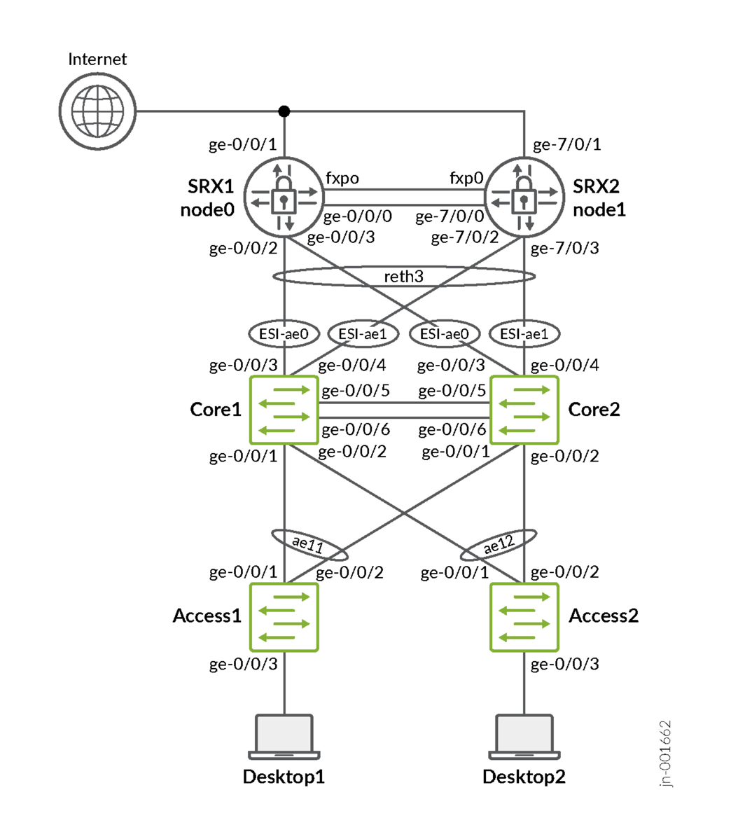
When using SRX Series Firewalls in chassis cluster mode, special attention must be given to the LAG configuration toward the EVPN fabric. This is necessary because VRRP is not used in an SRX chassis cluster. The recommended design operates as follows:
- A single reth interface aggregates all four links on the SRX chassis cluster.
- The reth interface is configured for LAG with active LACP.
- All four SRX chassis cluster interfaces operate with active LACP at the same time.
- The SRX chassis cluster determines which node is active.
- The standby node does not respond to ARP requests.
- Only the ae0 or ae1 interfaces on the fabric learn the active SRX remote MAC address.
- You need two fabric ae* LAGs.
- They are required to be ESI-LAGs from fabric nodes.
- They must use the same AE index key toward the corresponding SRX cluster node.
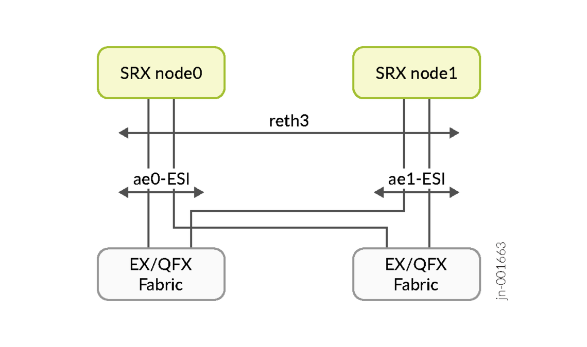
Fabric Configuration
The full workflow for fabric creation is intentionally not shown here, as the focus is on the components required to understand bridged overlay operation and the necessary changes. For more details on EVPN multihoming deployment, refer to the following JVD.
Switch Template
Below is the JSON file that was used as the switch template for this fabric.
{
  "additional_config_cmds": [],
  "networks": {
    "vlan1031": {
      "vlan_id": "1031",
      "subnet": "",
      "subnet6": ""
    },
    "vlan1033": {
      "vlan_id": "1033",
      "subnet": "",
      "subnet6": ""
    },
    "vlan1081": {
      "vlan_id": "1081",
      "subnet": "",
      "subnet6": ""
    },
    "vlan1088": {
      "vlan_id": "1088",
      "subnet": "",
      "subnet6": ""
    },
    "vlan1091": {
      "vlan_id": "1091",
      "subnet": "",
      "subnet6": ""
    },
    "vlan1099": {
      "vlan_id": "1099",
      "subnet": "",
      "subnet6": ""
    }
  },
  "port_usages": {
    "dynamic": {
      "mode": "dynamic",
      "rules": []
    },
    "vlan1088": {
      "mode": "access",
      "disabled": false,
      "port_network": "vlan1088",
      "voip_network": null,
      "stp_edge": false,
      "mac_auth_protocol": null,
      "all_networks": false,
      "networks": null,
      "port_auth": null,
      "enable_mac_auth": null,
      "mac_auth_only": null,
      "guest_network": null,
      "bypass_auth_when_server_down": null,
      "speed": "auto",
      "duplex": "auto",
      "mac_limit": 0,
      "persist_mac": false,
      "poe_disabled": false,
      "enable_qos": false,
      "storm_control": {},
      "mtu": null,
      "description": "",
      "disable_autoneg": false,
      "use_vstp": false,
      "allow_multiple_supplicants": null,
      "dynamic_vlan_networks": null,
      "stp_p2p": false,
      "stp_no_root_port": false,
      "reauth_interval": null
    },
    "vlan1099": {
      "mode": "access",
      "disabled": false,
      "port_network": "vlan1099",
      "voip_network": null,
      "stp_edge": false,
      "mac_auth_protocol": null,
      "all_networks": false,
      "networks": null,
      "port_auth": null,
      "enable_mac_auth": null,
      "mac_auth_only": null,
      "guest_network": null,
      "bypass_auth_when_server_down": null,
      "speed": "auto",
      "duplex": "auto",
      "mac_limit": 0,
      "persist_mac": false,
      "poe_disabled": false,
      "enable_qos": false,
      "storm_control": {},
      "mtu": null,
      "description": "",
      "disable_autoneg": false,
      "use_vstp": false,
      "allow_multiple_supplicants": null,
      "dynamic_vlan_networks": null,
      "stp_p2p": false,
      "stp_no_root_port": false,
      "reauth_interval": null
    },
    "fabric-uplink": {
      "mode": "trunk",
      "disabled": false,
      "port_network": null,
      "voip_network": null,
      "stp_edge": false,
      "use_vstp": false,
      "port_auth": null,
      "allow_multiple_supplicants": null,
      "enable_mac_auth": null,
      "mac_auth_only": null,
      "guest_network": null,
      "bypass_auth_when_server_down": null,
      "dynamic_vlan_networks": null,
      "stp_p2p": false,
      "stp_no_root_port": false,
      "server_reject_network": null,
      "server_fail_network": null,
      "mac_auth_protocol": null,
      "reauth_interval": null,
      "all_networks": false,
      "networks": [
        "vlan1031",
        "vlan1033",
        "vlan1081",
        "vlan1088",
        "vlan1091",
        "vlan1099"
      ],
      "speed": "auto",
      "duplex": "auto",
      "mac_limit": 0,
      "persist_mac": false,
      "poe_disabled": false,
      "enable_qos": false,
      "storm_control": {},
      "mtu": null,
      "description": "",
      "disable_autoneg": false
    }
  },
  "switch_matching": {
    "enable": true,
    "rules": []
  },
  "switch_mgmt": {
    "config_revert_timer": 10,
    "root_password": "juniper123",
    "local_accounts": {},
    "protect_re": {
      "enabled": false
    },
    "tacacs": {
      "enabled": false
    },
    "dhcp_option_fqdn": false
  },
  "mist_nac": {
    "enabled": true,
    "network": null
  },
  "radius_config": {
    "auth_servers": [],
    "acct_servers": [],
    "auth_servers_timeout": 5,
    "auth_servers_retries": 3,
    "fast_dot1x_timers": false,
    "acct_interim_interval": 0,
    "auth_server_selection": "ordered",
    "coa_enabled": false,
    "coa_port": ""
  },
  "vrf_config": {
    "enabled": false
  },
  "remote_syslog": {
    "enabled": false
  },
  "snmp_config": {
    "enabled": false
  },
  "dhcp_snooping": {
    "enabled": false
  },
  "dns_servers": [],
  "dns_suffix": [],
  "ntp_servers": [],
  "acl_policies": [],
  "port_mirroring": {},
  "disabled_system_defined_port_usages": [],
  "extra_routes": {},
  "extra_routes6": {},
  "bgp_config": null,
  "routing_policies": {},
  "name": "evpnmh-bridged-overlay"
}
In this example, six VLANs have been created. Only the name and VLAN ID should be configured for each. Do not assign any IPv4 or IPv6 subnets, as doing so would defeat the purpose of using a bridged overlay.
- Network=
1- Name=
vlan1031 - VLAN ID=
1031
- Name=
- Network=
2- Name=
vlan1033 - VLAN ID=
1033
- Name=
- Network=
3- Name=
vlan1081 - VLAN ID=
1081
- Name=
- Network=
4- Name=
vlan1088 - VLAN ID=
1088
- Name=
- Network=
5- Name=
vlan1091 - VLAN ID=
1091
- Name=
- Network=
6- Name=
vlan1099 - VLAN ID=
1099
- Name=
Next, configure a port profile. Instead of using a predefined profile such as “uplink,” create a custom one to control which VLANs from the fabric are shared with the WAN router in case of misconfiguration. Configure the port profile as follows:
- Name=
fabric-uplink - Port Enabled=
Checked - Mode=
Trunk - Port Network=
None - Trunk Networks=
vlan1031andvlan1033andvlan1081andvlan1088andvlan1091andvlan1099
Fabric Configuration
When creating the EVPN multihoming fabric, the default settings can be used without any changes. Proceed through the steps until you reach the Configure Networks page, where you should perform the following actions:
- Import the six VLANs from the switch template
- Ensure that under Other IP Configuration no IP address is shown as none of your networks should have any subnet defined, just the VLAN ID.
- VRF configuration:
- Disabled=
Checked - Instances=None configured.
- Disabled=
- DHCP Relay=
Disabled - Access ESI-LAG Name=
fabric - Trunk Networks=Ensure your six VLANs are automatically added.
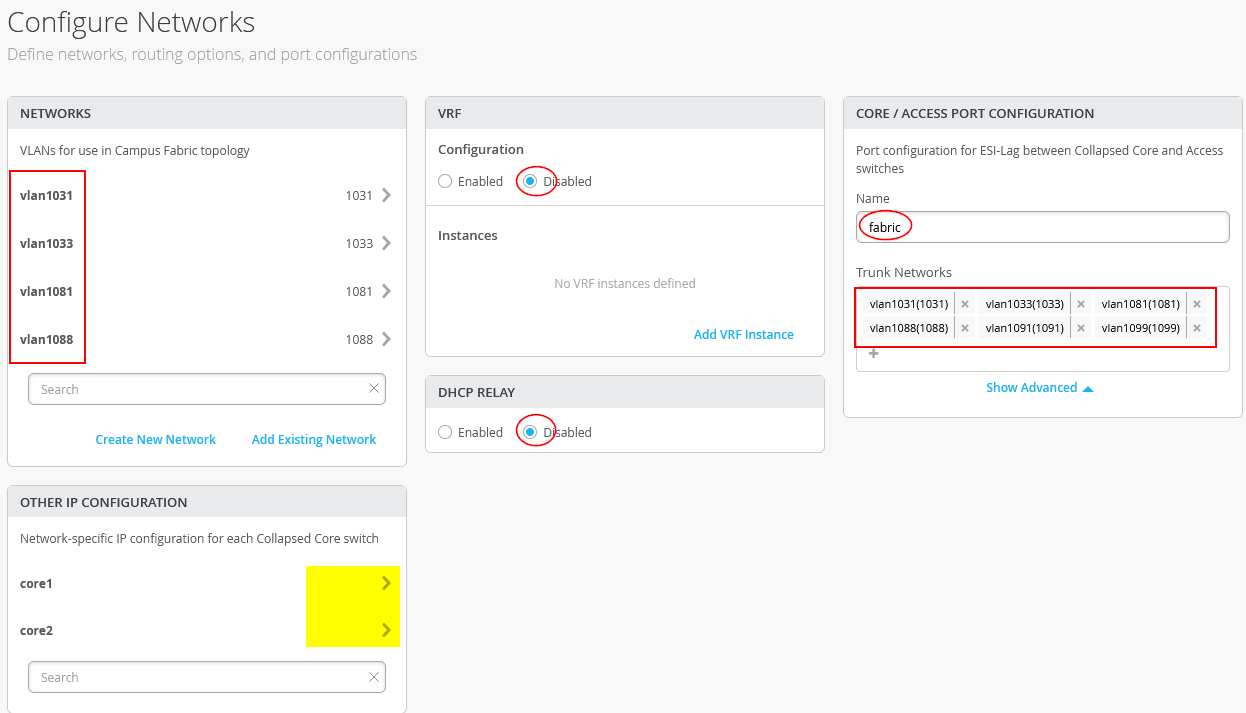
Finalize the campus fabric configuration dialogue.
Check the created fabric.
Add the wired client port configuration for the access switches, which is not shown here.
Now, create on the collapsed-core switches core1 and core2 in the fabric uplink configuration.
On core1 and core2, configure the following port configuration:
- First uplink port:
- Port ID=
ge-0/0/3 - Interface=
L2 interface - Configuration Profile=
fabric-uplink - Port Aggregation=
Enabled - AE Index=
0(all links to WAN router node0 have this ID) - ESI-LAG=
CheckedMANDATORY
- Port ID=
- Second uplink port:
- Port ID=
ge-0/0/4 - Interface=
L2 interface - Configuration Profile=
fabric-uplink - Port Aggregation=
Enabled - AE Index=
1(all links to WAN router node1 have this ID) - ESI-LAG=
CheckedMANDATORY
- Port ID=
WAN Router Setup
Before configuring the WAN Edge template, you need to do the following
- Deploy two SKU SRX Series Firewalls with HA links needed as standalone firewalls.
- Add the necessary AppID licenses to the devices.
- Change the site configuration to My SRX devices have an
App Track license=
Checked - Adopt or claim the SRX Series Firewalls until they appear in the Juniper Mist inventory.
- Select two SRX Series Firewalls in the inventory and choose Assign to Site. Enable cluster mode during the site assignment.
- Wait 15 minutes.
- Go to WAN-Edges -> Site and review the WAN Edge cluster status. Ensure that AppSecure is running as below.
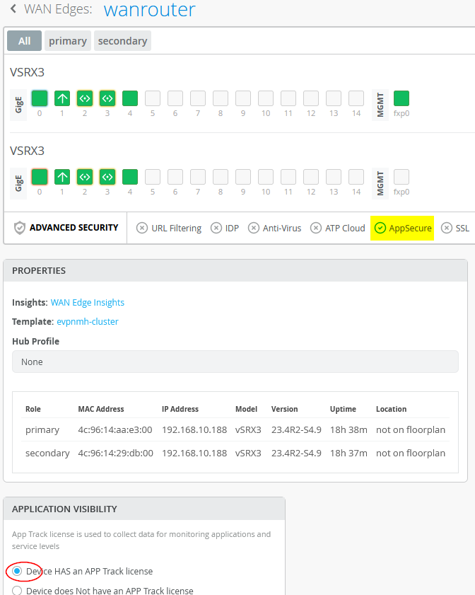
Now you can build a WAN Edge Template (or Hub-Profile).
Below is the JSON file that was used as the WAN Edge template
{
  "type": "standalone",
  "additional_config_cmds": [
    "set security zones security-zone vlan1031 host-inbound-traffic system-services ping",
    "set security zones security-zone vlan1033 host-inbound-traffic system-services ping",
    "set security zones security-zone vlan1081 host-inbound-traffic system-services ping",
    "set security zones security-zone vlan1088 host-inbound-traffic system-services ping",
    "set security zones security-zone vlan1091 host-inbound-traffic system-services ping",
    "set security zones security-zone vlan1099 host-inbound-traffic system-services ping"
  ],
  "ip_configs": {
    "vlan1031": {
      "type": "static",
      "ip": "10.31.31.1",
      "netmask": "/24"
    },
    "vlan1033": {
      "type": "static",
      "ip": "10.33.33.1",
      "netmask": "/24"
    },
    "vlan1081": {
      "type": "static",
      "ip": "10.81.81.1",
      "netmask": "/24"
    },
    "vlan1088": {
      "type": "static",
      "ip": "10.88.88.1",
      "netmask": "/24"
    },
    "vlan1091": {
      "type": "static",
      "ip": "10.91.91.1",
      "netmask": "/24"
    },
    "vlan1099": {
      "type": "static",
      "ip": "10.99.99.1",
      "netmask": "/24"
    }
  },
  "dhcpd_config": {
    "enabled": true,
    "vlan1031": {
      "type": "local",
      "ip_start": "10.31.31.10",
      "ip_end": "10.31.31.250",
      "gateway": "10.31.31.1",
      "dns_servers": [
        "8.8.8.8",
        "9.9.9.9"
      ],
      "options": {},
      "lease_time": 86400,
      "fixed_bindings": {}
    },
    "vlan1033": {
      "type": "local",
      "ip_start": "10.33.33.10",
      "ip_end": "10.33.33.250",
      "gateway": "10.33.33.1",
      "dns_servers": [
        "8.8.8.8",
        "9.9.9.9"
      ],
      "options": {},
      "lease_time": 86400,
      "fixed_bindings": {}
    },
    "vlan1081": {
      "type": "local",
      "ip_start": "10.81.81.10",
      "ip_end": "10.81.81.250",
      "gateway": "10.81.81.1",
      "dns_servers": [
        "8.8.8.8",
        "9.9.9.9"
      ],
      "options": {},
      "lease_time": 86400,
      "fixed_bindings": {}
    },
    "vlan1088": {
      "type": "local",
      "ip_start": "10.88.88.10",
      "ip_end": "10.88.88.250",
      "gateway": "10.88.88.1",
      "dns_servers": [
        "8.8.8.8",
        "9.9.9.9"
      ],
      "options": {},
      "lease_time": 86400,
      "fixed_bindings": {}
    },
    "vlan1091": {
      "type": "local",
      "ip_start": "10.91.91.10",
      "ip_end": "10.91.91.250",
      "gateway": "10.91.91.1",
      "dns_servers": [
        "8.8.8.8",
        "9.9.9.9"
      ],
      "options": {},
      "lease_time": 86400,
      "fixed_bindings": {}
    },
    "vlan1099": {
      "type": "local",
      "ip_start": "10.99.99.10",
      "ip_end": "10.99.99.250",
      "gateway": "10.99.99.1",
      "dns_servers": [
        "8.8.8.8",
        "9.9.9.9"
      ],
      "options": {},
      "lease_time": 86400,
      "fixed_bindings": {}
    }
  },
  "ospf_areas": {},
  "port_config": {
    "ge-0/0/1": {
      "name": "WAN-N0",
      "usage": "wan",
      "aggregated": false,
      "redundant": false,
      "critical": false,
      "disabled": false,
      "wan_type": "broadband",
      "ip_config": {
        "type": "dhcp"
      },
      "disable_autoneg": false,
      "wan_source_nat": {
        "disabled": false
      },
      "vpn_paths": {}
    },
    "ge-7/0/1": {
      "name": "WAN-N1",
      "usage": "wan",
      "aggregated": false,
      "redundant": false,
      "critical": false,
      "disabled": false,
      "wan_type": "broadband",
      "ip_config": {
        "type": "dhcp"
      },
      "disable_autoneg": false,
      "wan_source_nat": {
        "disabled": false
      },
      "vpn_paths": {}
    },
    "ge-0/0/2,ge-0/0/3,ge-7/0/2,ge-7/0/3": {
      "networks": [
        "vlan1033",
        "vlan1088",
        "vlan1031",
        "vlan1091",
        "vlan1081",
        "vlan1099"
      ],
      "usage": "lan",
      "aggregated": true,
      "ae_disable_lacp": false,
      "ae_lacp_force_up": false,
      "ae_idx": "0",
      "redundant": true,
      "reth_idx": 3,
      "reth_node": "node0",
      "critical": false,
      "disabled": false,
      "redundant_group": "3"
    }
  },
  "bgp_config": {},
  "routing_policies": {},
  "extra_routes": {},
  "path_preferences": {
    "LAN": {
      "strategy": "ecmp",
      "paths": [
        {
          "type": "local",
          "networks": [
            "vlan1031"
          ]
        },
        {
          "type": "local",
          "networks": [
            "vlan1033"
          ]
        },
        {
          "type": "local",
          "networks": [
            "vlan1081"
          ]
        },
        {
          "type": "local",
          "networks": [
            "vlan1088"
          ]
        },
        {
          "type": "local",
          "networks": [
            "vlan1091"
          ]
        },
        {
          "type": "local",
          "networks": [
            "vlan1099"
          ]
        }
      ]
    },
    "WAN": {
      "strategy": "ordered",
      "paths": [
        {
          "name": "WAN-N0",
          "type": "wan"
        },
        {
          "name": "WAN-N1",
          "type": "wan"
        }
      ]
    }
  },
  "service_policies": [
    {
      "name": "branch-hairpin",
      "tenants": [
        "vlan1031",
        "vlan1033",
        "vlan1081",
        "vlan1088",
        "vlan1091",
        "vlan1099"
      ],
      "services": [
        "fabric"
      ],
      "action": "allow",
      "path_preference": "LAN",
      "idp": {
        "enabled": false
      }
    },
    {
      "name": "towards-internet",
      "tenants": [
        "vlan1031",
        "vlan1033",
        "vlan1081",
        "vlan1088",
        "vlan1091",
        "vlan1099"
      ],
      "services": [
        "any"
      ],
      "action": "allow",
      "path_preference": "WAN",
      "idp": {
        "enabled": false
      }
    }
  ],
  "gateway_mgmt": {
    "host_out_policies": {},
    "overlay_ip": {}
  },
  "host_in_policies": [],
  "vrf_instances": {},
  "tunnel_configs": {},
  "tunnel_provider_options": {
    "jse": {},
    "zscaler": {}
  },
  "oob_ip_config": {
    "type": "dhcp",
    "node1": {
      "type": "dhcp"
    }
  },
  "ospf_config": {
    "enabled": false,
    "areas": {}
  },
  "remote_syslog": {
    "enabled": false,
    "files": [],
    "servers": [],
    "users": [],
    "time_format": "",
    "console": {
      "contents": []
    }
  },
  "name": "evpnmh-cluster"
}
If you are not using the JSON file, follow the manual setup described below. Under Organization -> Applications, add a custom application for “fabric” that includes all RFC1918 networks, and another for default route injection, which is currently required to advertise a default route toward the EVPN fabric. Create the following applications:
- Name=
fabric - Type=
Custom Apps - IP Addresses=
10.0.0.0/8and172.16.0.0/12and192.168.0.0/16
Under Organization -> Networks add the subnets for each of the six VLANs.
- Network=
1- Name=
vlan1031 - Subnet IP Address=
10.31.31.0 - Prefix Length=
24 - VLAN ID=
1031 - Access to Mist Cloud=
Enabled
- Name=
- Network=
2- Name=
vlan1033 - Subnet IP Address=
10.33.33.0 - Prefix Length=
24 - VLAN ID=
1033 - Access to Mist Cloud=
Enabled
- Name=
- Network=
3- Name=
vlan1081 - Subnet IP Address=
10.81.81.0 - Prefix Length=
24 - VLAN ID=
1081 - Access to Mist Cloud=
Enabled
- Name=
- Network=
4- Name=
vlan1088 - Subnet IP Address=
10.88.88.0 - Prefix Length=
24 - VLAN ID=
1088 - Access to Mist Cloud=
Enabled
- Name=
- Network=
5- Name=
vlan1091 - Subnet IP Address=
10.91.91.0 - Prefix Length=
24 - VLAN ID=
1091 - Access to Mist Cloud=
Enabled
- Name=
- Network=
6- Name=
vlan1099 - Subnet IP Address=
10.99.99.0 - Prefix Length=
24 - VLAN ID=
1099 - Access to Mist Cloud=
Enabled
- Name=
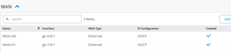
In our design, we used dynamic IP addresses on the WAN interfaces for our lab.
Next is the configuration of the LAN interfaces. Configure the following six LAN IP gateways:
- Gateway=
1- Network=
vlan1031 - IP Address=
10.31.31.1 - Prefix Length=
24
- Network=
- Gateway=
2- Network=
vlan1033 - IP Address=
10.33.33.1 - Prefix Length=
24
- Network=
- Gateway=
3- Network=
vlan1081 - IP Address=
10.81.81.1 - Prefix Length=
24
- Network=
- Gateway=
4- Network=
vlan1088 - IP Address=
10.88.88.1 - Prefix Length=
24
- Network=
- Gateway=
5- Network=
vlan1091 - IP Address=
10.91.91.1 - Prefix Length=
24
- Network=
- Gateway=
6- Network=
vlan1099 - IP Address=
10.99.99.1 - Prefix Length=
24
- Network=
Next, enable DHCP and configure a DHCP server for each VLAN. The complete DHCP server configuration for all VLANs is shown below:
- VLAN=
1- Network=
vlan1031 - DHCP=
Server - IP Start=
10.31.31.10 - IP End=
10.31.31.250 - Gateway=
10.31.31.1 - DNS Servers=
8.8.8.8,9.9.9.9
- Network=
- VLAN=
2- Network=
vlan1033 - DHCP=
Server - IP Start=
10.33.33.10 - IP End=
10.33.33.250 - Gateway=
10.33.33.1 - DNS Servers=
8.8.8.8,9.9.9.9
- Network=
- VLAN=
3- Network=
vlan1081 - DHCP=
Server - IP Start=
10.81.81.10 - IP End=
10.81.81.250 - Gateway=
10.81.81.1 - DNS Servers=
8.8.8.8,9.9.9.9
- Network=
- VLAN=
4- Network=
vlan1088 - DHCP=
Server - IP Start=
10.88.88.10 - IP End=
10.88.88.250 - Gateway=
10.88.88.1 - DNS Servers=
8.8.8.8,9.9.9.9
- Network=
- VLAN=
5- Network=
vlan1091 - DHCP=
Server - IP Start=
10.91.91.10 - IP End=
10.91.91.250 - Gateway=
10.91.91.1 - DNS Servers=
8.8.8.8,9.9.9.9
- Network=
- VLAN=
6- Network=
vlan1099 - DHCP=
Server - IP Start=
10.99.99.10 - IP End=
10.99.99.250 - Gateway=
10.99.99.1 - DNS Servers=
8.8.8.8,9.9.9.9
- Network=
Then configure the LAG with the LAN interfaces towards fabric like that shown below:
- Interface=
ge-0/0/2,ge-0/0/3,ge-7/0/2,ge-7/0/3 - Port Aggregation=
Checked/Enabled- Disable LACP=
Unchecked - Enable Force Up=
Unchecked - AE Index=
0
- Disable LACP=
- Redundant=
Checked/Enabled- Redundant Index=
3 - Redundant Group=
3 - Primary Node=
node0
- Redundant Index=
- Networks=
vlan1031andvlan1033andvlan1081andvlan1088andvlan1091andvlan1099
The result should look like the image below.

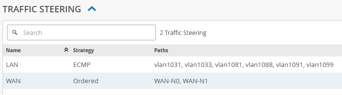
The traffic steering rules are straightforward, as shown below:
- Create a LAN traffic steering rule using ECMP that includes all six VLAN interfaces.
- Create a WAN traffic steering rule that includes both WAN interfaces.
If you are using two physical SSR devices as the WAN router, do not set LAN in the first application policy rule as shown below. Leave the traffic steering field empty in the first application policy rule.
For application policies, configure the following:
- Rule=
1- Name=
branch-hairpin - Network=
vlan1031andvlan1033andvlan1081andvlan1088andvlan1091andvlan1099 - Application=
fabric - Traffic Steering=
LAN
- Name=
- Rule=
2- Name=
towards-internet - Network=
vlan1031andvlan1033andvlan1081andvlan1088andvlan1091andvlan1099 - Application=
any - Traffic Steering=
WAN
- Name=
On the SRX, add the configuration below to allow pinging the LAN interfaces assigned to the SRX chassis cluster. This is recommended for troubleshooting, and some applications may require it.
set security zones security-zone vlan1031 host-inbound-traffic system-services ping
set security zones security-zone vlan1033 host-inbound-traffic system-services ping
set security zones security-zone vlan1081 host-inbound-traffic system-services ping
set security zones security-zone vlan1088 host-inbound-traffic system-services ping
set security zones security-zone vlan1091 host-inbound-traffic system-services ping
set security zones security-zone vlan1099 host-inbound-traffic system-services ping
Testing Your Configuration
The following steps validate the configuration and traffic flow through the design.
Begin with the desktop1 VM connected to the access1 switch.
# check my interface configuration
root@desktop1:~# ip a
.
4: ens5: <BROADCAST,MULTICAST,UP,LOWER_UP> mtu 1500 qdisc fq_codel state UP group default qlen 1000
    link/ether 52:54:00:ad:a6:3e brd ff:ff:ff:ff:ff:ff
    inet 10.99.99.99/24 brd 10.99.99.255 scope global ens5
       valid_lft forever preferred_lft forever
.
# try to ping default Gateway which is my SRX cluster
root@desktop1:~# ping -c3 10.99.99.1
PING 10.99.99.1 (10.99.99.1) 56(84) bytes of data.
64 bytes from 10.99.99.1: icmp_seq=1 ttl=64 time=1.39 ms
64 bytes from 10.99.99.1: icmp_seq=2 ttl=64 time=1.59 ms
64 bytes from 10.99.99.1: icmp_seq=3 ttl=64 time=1.85 ms
.
# try to ping other desktop VM in other VLAN
root@desktop1:~# ping -c3 10.88.88.88
PING 10.88.88.88 (10.88.88.88) 56(84) bytes of data.
64 bytes from 10.88.88.88: icmp_seq=1 ttl=63 time=2.91 ms
64 bytes from 10.88.88.88: icmp_seq=2 ttl=63 time=2.95 ms
64 bytes from 10.88.88.88: icmp_seq=3 ttl=63 time=2.85 ms
.
# try to ping internet
root@desktop1:~# ping -c3 8.8.8.8
PING 8.8.8.8 (8.8.8.8) 56(84) bytes of data.
64 bytes from 8.8.8.8: icmp_seq=1 ttl=117 time=19.2 ms
64 bytes from 8.8.8.8: icmp_seq=2 ttl=117 time=18.6 ms
64 bytes from 8.8.8.8: icmp_seq=3 ttl=117 time=20.9 ms
.
# review ARP cache
root@desktop1:~# arp -n
Address                  HWtype  HWaddress           Flags Mask            Iface
10.99.99.1               ether   00:10:db:ff:10:03   C                     ens5
The following section reviews the status of the collapsed core1 switch through a remote console session.
root@core1> show lldp neighbors
Local Interface    Parent Interface    Chassis Id                               Port info          System Name
ge-0/0/3           ae0                 00:10:db:ff:10:00                        ge-0/0/2            wanrouter_node0
ge-0/0/4           ae1                 00:10:db:ff:10:00                        ge-7/0/2            wanrouter_node0
ge-0/0/1           ae11                2c:6b:f5:4f:c9:c0                        ge-0/0/1            access1
ge-0/0/2           ae12                2c:6b:f5:9b:39:c0                        ge-0/0/2            access2
ge-0/0/5           -                   2c:6b:f5:9c:5b:c0                        evpn_downlink-to-0200043ea013 core2
ge-0/0/6           -                   2c:6b:f5:9c:5b:c0                        evpn_uplink-to-0200043ea013 core2
.
root@core1> show lacp interfaces
Aggregated interface: ae11
    LACP state:           Role   Exp   Def  Dist  Col  Syn  Aggr  Timeout  Activity
      ge-0/0/1           Actor    No    No   Yes  Yes  Yes   Yes     Fast    Active
      ge-0/0/1         Partner    No    No   Yes  Yes  Yes   Yes     Fast    Active
    LACP protocol:        Receive State  Transmit State          Mux State
      ge-0/0/1                  Current   Fast periodic Collecting distributing
.
Aggregated interface: ae12
    LACP state:           Role   Exp   Def  Dist  Col  Syn  Aggr  Timeout  Activity
      ge-0/0/2           Actor    No    No   Yes  Yes  Yes   Yes     Fast    Active
      ge-0/0/2         Partner    No    No   Yes  Yes  Yes   Yes     Fast    Active
    LACP protocol:        Receive State  Transmit State          Mux State
      ge-0/0/2                  Current   Fast periodic Collecting distributing
.
Aggregated interface: ae0
    LACP state:           Role   Exp   Def  Dist  Col  Syn  Aggr  Timeout  Activity
      ge-0/0/3           Actor    No    No   Yes  Yes  Yes   Yes     Fast    Active
      ge-0/0/3         Partner    No    No   Yes  Yes  Yes   Yes     Fast    Active
    LACP protocol:        Receive State  Transmit State          Mux State
      ge-0/0/3                  Current   Fast periodic Collecting distributing
.
Aggregated interface: ae1
    LACP state:           Role   Exp   Def  Dist  Col  Syn  Aggr  Timeout  Activity
      ge-0/0/4           Actor    No    No   Yes  Yes  Yes   Yes     Fast    Active
      ge-0/0/4         Partner    No    No   Yes  Yes  Yes   Yes     Fast    Active
    LACP protocol:        Receive State  Transmit State          Mux State
      ge-0/0/4                  Current   Fast periodic Collecting distributing
.
root@core1> show ethernet-switching table
.
MAC flags (S - static MAC, D - dynamic MAC, L - locally learned, P - Persistent static, C - Control MAC
           SE - statistics enabled, NM - non configured MAC, R - remote PE MAC, O - ovsdb MAC,
           B - Blocked MAC)
.
Ethernet switching table : 3 entries, 3 learned
Routing instance : evpn_vs
   Vlan                MAC                 MAC       GBP    Logical                SVLBNH/      Active
   name                address             flags     tag    interface              VENH Index   source
   vlan1088            52:54:00:8f:7c:a0   DR               ae12.0
   vlan1099            00:10:db:ff:10:03   DLR              ae0.0
   vlan1099            52:54:00:ad:a6:3e   DLR              ae11.0
The following section reviews the status of the SRX chassis cluster using a remote console.
root@wanrouter_node0> show lldp neighbors
Local Interface    Parent Interface    Chassis Id                               Port info          System Name
ge-0/0/1           -                   00:10:db:ff:10:00                        fxp0                wanrouter_node0
ge-7/0/1           -                   00:10:db:ff:10:00                        fxp0                wanrouter_node0
fxp0               -                   00:10:db:ff:10:00                        ge-0/0/1            wanrouter_node0
ge-7/0/1           -                   00:10:db:ff:10:00                        ge-0/0/1            wanrouter_node0
fxp0               -                   00:10:db:ff:10:00                        ge-7/0/1            wanrouter_node0
ge-0/0/1           -                   00:10:db:ff:10:00                        ge-7/0/1            wanrouter_node0
ge-0/0/2           reth3               2c:6b:f5:1a:a3:c0                        ge-0/0/3            core1
ge-7/0/2           reth3               2c:6b:f5:1a:a3:c0                        ge-0/0/4            core1
ge-0/0/3           reth3               2c:6b:f5:9c:5b:c0                        ge-0/0/3            core2
ge-7/0/3           reth3               2c:6b:f5:9c:5b:c0                        ge-0/0/4            core2
.
root@wanrouter_node0> show lacp interfaces
Aggregated interface: reth3
    LACP state:           Role   Exp   Def  Dist  Col  Syn  Aggr  Timeout  Activity
      ge-0/0/2           Actor    No    No   Yes  Yes  Yes   Yes     Fast    Active
      ge-0/0/2         Partner    No    No   Yes  Yes  Yes   Yes     Fast    Active
      ge-0/0/3           Actor    No    No   Yes  Yes  Yes   Yes     Fast    Active
      ge-0/0/3         Partner    No    No   Yes  Yes  Yes   Yes     Fast    Active
      ge-7/0/2           Actor    No    No   Yes  Yes  Yes   Yes     Fast    Active
      ge-7/0/2         Partner    No    No   Yes  Yes  Yes   Yes     Fast    Active
      ge-7/0/3           Actor    No    No   Yes  Yes  Yes   Yes     Fast    Active
      ge-7/0/3         Partner    No    No   Yes  Yes  Yes   Yes     Fast    Active
    LACP protocol:        Receive State  Transmit State          Mux State
      ge-0/0/2                  Current   Fast periodic Collecting distributing
      ge-0/0/3                  Current   Fast periodic Collecting distributing
      ge-7/0/2                  Current   Fast periodic Collecting distributing
      ge-7/0/3                  Current   Fast periodic Collecting distributing
.
root@wanrouter_node0> show route table apbr_LAN.inet.0
.
apbr_LAN.inet.0: 7 destinations, 7 routes (7 active, 0 holddown, 0 hidden)
+ = Active Route, - = Last Active, * = Both
.
10.31.31.0/24      *[Direct/0] 21:40:24
                    >  via reth3.1031
10.33.33.0/24      *[Direct/0] 21:40:24
                    >  via reth3.1033
10.81.81.0/24      *[Direct/0] 21:40:24
                    >  via reth3.1081
10.88.88.0/24      *[Direct/0] 21:40:24
                    >  via reth3.1088
10.91.91.0/24      *[Direct/0] 21:40:24
                    >  via reth3.1091
10.99.99.0/24      *[Direct/0] 21:40:24
                    >  via reth3.1099
100.100.0.1/32     *[Direct/0] 21:57:20
                    >  via lo0.0
.
root@wanrouter_node0> show interfaces terse
Interface               Admin Link Proto    Local                 Remote
ge-0/0/0                up    up
ge-0/0/0.0              up    up   aenet    --> fab0.0
.
ge-0/0/1                up    up
ge-0/0/1.0              up    up   inet     192.168.10.188/24
ge-0/0/2                up    up
ge-0/0/2.1031           up    up   aenet    --> reth3.1031
ge-0/0/2.1033           up    up   aenet    --> reth3.1033
ge-0/0/2.1081           up    up   aenet    --> reth3.1081
ge-0/0/2.1088           up    up   aenet    --> reth3.1088
ge-0/0/2.1091           up    up   aenet    --> reth3.1091
ge-0/0/2.1099           up    up   aenet    --> reth3.1099
ge-0/0/2.32767          up    up   aenet    --> reth3.32767
ge-0/0/3                up    up
ge-0/0/3.1031           up    up   aenet    --> reth3.1031
ge-0/0/3.1033           up    up   aenet    --> reth3.1033
ge-0/0/3.1081           up    up   aenet    --> reth3.1081
ge-0/0/3.1088           up    up   aenet    --> reth3.1088
ge-0/0/3.1091           up    up   aenet    --> reth3.1091
ge-0/0/3.1099           up    up   aenet    --> reth3.1099
ge-0/0/3.32767          up    up   aenet    --> reth3.32767
ge-0/0/4                up    up
ge-7/0/0                up    up
ge-7/0/0.0              up    up   aenet    --> fab1.0
ge-7/0/1                up    up
ge-7/0/1.0              up    up   inet     192.168.10.170/24
ge-7/0/2                up    up
ge-7/0/2.1031           up    up   aenet    --> reth3.1031
ge-7/0/2.1033           up    up   aenet    --> reth3.1033
ge-7/0/2.1081           up    up   aenet    --> reth3.1081
ge-7/0/2.1088           up    up   aenet    --> reth3.1088
ge-7/0/2.1091           up    up   aenet    --> reth3.1091
ge-7/0/2.1099           up    up   aenet    --> reth3.1099
ge-7/0/2.32767          up    up   aenet    --> reth3.32767
ge-7/0/3                up    up
ge-7/0/3.1031           up    up   aenet    --> reth3.1031
ge-7/0/3.1033           up    up   aenet    --> reth3.1033
ge-7/0/3.1081           up    up   aenet    --> reth3.1081
ge-7/0/3.1088           up    up   aenet    --> reth3.1088
ge-7/0/3.1091           up    up   aenet    --> reth3.1091
ge-7/0/3.1099           up    up   aenet    --> reth3.1099
ge-7/0/3.32767          up    up   aenet    --> reth3.32767
ge-7/0/4                up    up
dsc                     up    up
em0                     up    up
em0.0                   up    up   inet     129.16.0.1/2
                                            143.16.0.1/2
                                   tnp      0x1100001
fab0                    up    up
fab0.0                  up    up   inet     30.17.0.200/24
fab1                    up    up
fab1.0                  up    up   inet     30.18.0.200/24
fti0                    up    up
fxp0                    up    up
fxp0.0                  up    up   inet     192.168.10.174/24
gre                     up    up
ipip                    up    up
irb                     up    up
lo0                     up    up
lo0.0                   up    up   inet     100.100.0.1         --> 0/0
lo0.16384               up    up   inet     127.0.0.1           --> 0/0
lo0.16385               up    up   inet     10.0.0.1            --> 0/0
                                            10.0.0.16           --> 0/0
                                            128.0.0.1           --> 0/0
                                            128.0.0.4           --> 0/0
                                            128.0.1.16          --> 0/0
lo0.32768               up    up
.
reth0                   up    down
reth1                   up    down
reth2                   up    down
reth3                   up    up
reth3.1031              up    up   inet     10.31.31.1/24
reth3.1033              up    up   inet     10.33.33.1/24
reth3.1081              up    up   inet     10.81.81.1/24
reth3.1088              up    up   inet     10.88.88.1/24
reth3.1091              up    up   inet     10.91.91.1/24
reth3.1099              up    up   inet     10.99.99.1/24
reth3.32767             up    up
st0                     up    up
st0.16000               up    up
tap                     up    up
.
root@wanrouter_node0> show security flow session source-prefix 10.99.99.0/24
node0:
--------------------------------------------------------------------------
.
Session ID: 142675, Policy name: 01_towards-internet/50, HA State: Active, Timeout: 2, Session State: Valid
  In: 10.99.99.99/16 --> 8.8.8.8/5;icmp, Conn Tag: 0x0, If: reth3.1099, Pkts: 1, Bytes: 84,
  Out: 8.8.8.8/5 --> 192.168.10.188/49702;icmp, Conn Tag: 0x0, If: ge-0/0/1.0, Pkts: 1, Bytes: 84,
.
Session ID: 142681, Policy name: 01_towards-internet/50, HA State: Active, Timeout: 2, Session State: Valid
  In: 10.99.99.99/16 --> 8.8.8.8/6;icmp, Conn Tag: 0x0, If: reth3.1099, Pkts: 1, Bytes: 84,
  Out: 8.8.8.8/6 --> 192.168.10.188/54502;icmp, Conn Tag: 0x0, If: ge-0/0/1.0, Pkts: 1, Bytes: 84,
.
Session ID: 142687, Policy name: 01_towards-internet/50, HA State: Active, Timeout: 4, Session State: Valid
  In: 10.99.99.99/16 --> 8.8.8.8/7;icmp, Conn Tag: 0x0, If: reth3.1099, Pkts: 1, Bytes: 84,
  Out: 8.8.8.8/7 --> 192.168.10.188/48524;icmp, Conn Tag: 0x0, If: ge-0/0/1.0, Pkts: 1, Bytes: 84,
Total sessions: 3
.
node1:
--------------------------------------------------------------------------
Total sessions: 0
.
root@wanrouter_node0> show arp
MAC Address       Address         Name                      Interface               Flags
52:54:00:8f:7c:a0 10.88.88.88     10.88.88.88               reth3.1088              none
52:54:00:ad:a6:3e 10.99.99.99     10.99.99.99               reth3.1099              none
4c:96:14:29:db:ae 30.17.0.2       30.17.0.2                 fab0.0                  permanent
4c:96:14:aa:e3:ae 30.18.0.1       30.18.0.1                 fab1.0                  permanent
52:54:00:21:aa:cb 130.16.0.1      130.16.0.1                em0.0                   none
52:54:00:fd:97:b8 192.168.10.1    192.168.10.1              ge-7/0/1.0              none
52:54:00:fd:97:b8 192.168.10.1    192.168.10.1              ge-0/0/1.0              none
52:54:00:fd:97:b8 192.168.10.1    192.168.10.1              fxp0.0                  none
Total entries: 8