APPENDIX: WAN Router Integration into the Fabric
In general, there are several possible ways to attach a WAN router to a campus fabric.
- Using a L2 forwarding method:
- The fabric uplinks are configured as ESI-LAGs and contain one or more tagged VLANs (one for each VRF) to communicate with the WAN router.
- It is also necessary that you configure the IP address of the WAN router interface manually as the next-hop IP address for default-forwarding on each fabric VRF as already shown above.
- The WAN router itself needs to understand standard IEEE 802.3ad LAG with active LACP.
- If you have more than one WAN router attached for redundancy, it is advised to provide failover mechanisms between them for the interface IP addresses towards the fabric. VRRP is recommended.
- Routes between fabric and WAN router are only statically configured.
- Using an L3 forwarding method:
- The fabric uplinks are configured as L3 peer-to-peer IP links.
- Per fabric VRF, a peer-to-peer link needs to be established with the WAN router.
- Usually, there are multiple peer-to-peer links on a single physical uplink. Those are further segmented using tagged VLANs to provide isolation on the uplinks.
- There is no need to manually configure next hops for each VRF inside the fabric as it is assumed that the propagation of the default gateways will be obtained from the WAN router through a routing protocol.
- Between the fabric and the WAN router, a routing protocol must be established to exchange routes.
- The campus fabric supports exterior BGP and OSPF as routing protocols towards the WAN router.
The details of such integration are explained in the following JVD extension for all fabric types. We kept the explanations in this chapter brief because it’s better documented along with the backgrounds in the referred extension.
In our lab, we decided to go with L3 eBGP forwarding integration
with the SRX WAN router. Before doing this, we reviewed the routing
table for the corp-it VRF on the access1 switch, as
shown below:
root@access1> show route table corp-it.inet.0
corp-it.inet.0: 7 destinations, 8 routes (7 active, 0 holddown, 0 hidden)
@ = Routing Use Only, # = Forwarding Use Only
+ = Active Route, - = Last Active, * = Both
10.99.99.0/24      *[Direct/0] 03:54:18
                    >  via irb.1099
                    [EVPN/170] 03:47:12
                       to 10.255.240.24 via mge-0/0/36.0
                    >  to 10.255.240.20 via mge-0/0/37.0
10.99.99.1/32      *[Local/0] 03:54:18
                       Local via irb.1099
10.99.99.23/32     *[EVPN/7] 03:41:35
                    >  via irb.1099
10.99.99.42/32     *[EVPN/170] 03:42:49
                    >  to 10.255.240.24 via mge-0/0/36.0
                       to 10.255.240.20 via mge-0/0/37.0
10.99.99.99/32     *[EVPN/7] 03:39:08
                    >  via irb.1099
172.16.192.4/32    *[Direct/0] 03:54:19
                    >  via lo0.1
172.16.192.7/32    *[EVPN/170] 03:47:12
                       to 10.255.240.24 via mge-0/0/36.0
                    >  to 10.255.240.20 via mge-0/0/37.0
For our lab with one WAN router and three VRFs, the configurations can be reviewed from the figure below:
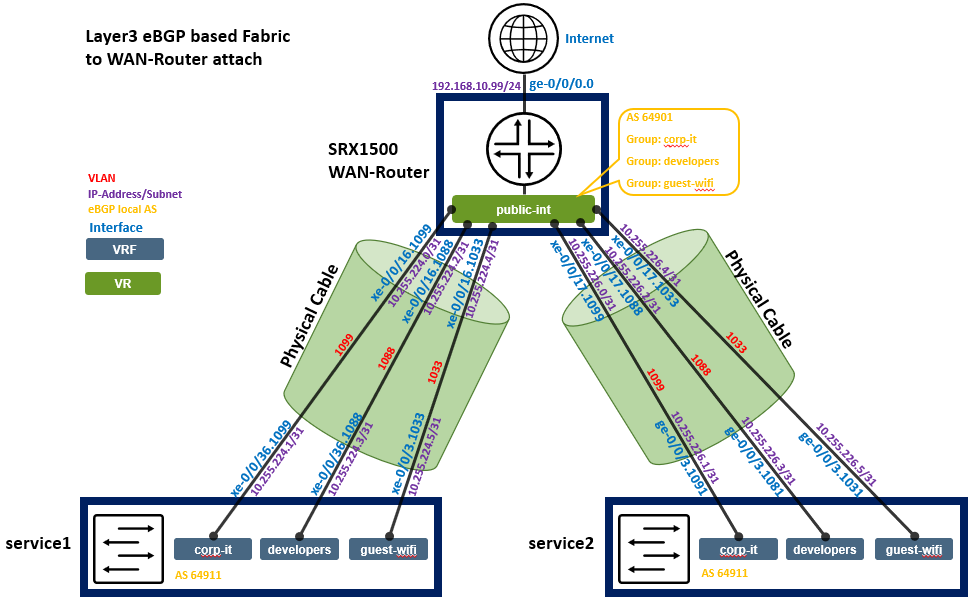
Below, you see the integration information again as a table for each peering to be configured.
| Switch | Switch AS | VRF | Service P2P IP | Service IF | WAN Router | WAN Router P2P IP | WAN Router AS | WAN Router IF | VLAN-ID |
|---|---|---|---|---|---|---|---|---|---|
| service1 | 64911 | corp-it | 10.255.224.1/31 | xe-0/0/36.1099 | wanrouter | 10.255.224.0/31 | 64901 | xe-0/0/16.1099 | 1099 |
| service1 | 64911 | developers | 10.255.224.3/31 | xe-0/0/36.1088 | wanrouter | 10.255.224.2/31 | 64901 | xe-0/0/16.1088 | 1088 |
| service1 | 64911 | guest-wifi | 10.255.224.5/31 | xe-0/0/36.1033 | wanrouter | 10.255.224.4/31 | 64901 | xe-0/0/16.1033 | 1033 |
| service2 | 64911 | corp-it | 10.255.226.1/31 | xe-0/0/36.1099 | wanrouter | 10.255.226.0/31 | 64901 | xe-0/0/17.1099 | 1099 |
| service2 | 64911 | developers | 10.255.226.3/31 | xe-0/0/36.1088 | wanrouter | 10.255.226.2/31 | 64901 | xe-0/0/17.1088 | 1088 |
| service2 | 64911 | guest-wifi | 10.255.226.5/31 | xe-0/0/36.1033 | wanrouter | 10.255.226.4/31 | 64901 | xe-0/0/17.1033 | 1033 |
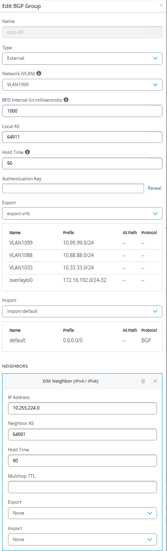
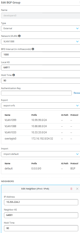
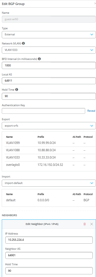
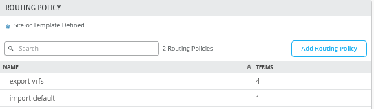
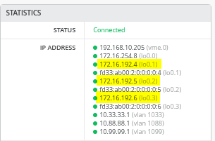
Configuration of service1 Block Switch for WAN Router Integration
We have a verbal description of what needs to be configured on this system here:
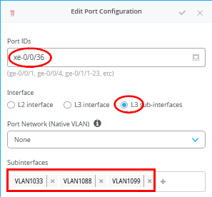
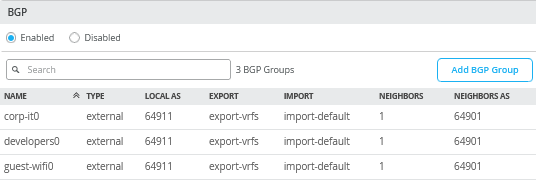
# configure the Additional IP-Subnet 10.255.224.1 255.255.255.254 to Network/VLAN:VLAN1099
# configure the Additional IP-Subnet 10.255.224.3 255.255.255.254 to Network/VLAN:VLAN1088
# configure the Additional IP-Subnet 10.255.224.5 255.255.255.254 to Network/VLAN:VLAN1033
# Then bind these 3 Network/VLANs to Port Interface xe-0/0/36 as L3-Sub-Interfaces with MTU=9018
.
# Enable BGP and create an Export policy called 'export-vrfs'
# Add to this export Policy the following Networks as:
# - Add Term w. Name=VLAN1099  Prefix=10.99.99.0/24  Protocol=None  Then=Accept
# - Add Term w. Name=VLAN1088  Prefix=10.88.88.0/24  Protocol=None  Then=Accept
# - Add Term w. Name=VLAN1033  Prefix=10.33.33.0/24  Protocol=None  Then=Accept
# - Add Term w. Name=overlaylo0 Prefix=172.16.192.0/24-32  Protocol=None  Then=Accept
.
# Create an Export policy called 'import-default'
# - Name=default  Prefix=0.0.0.0/0  Protocol=BGP  Action=Accept
.
# Create a BGP Group with:
# - Name=corp-it0
# - Type=External
# - Network (VLAN)=VLAN1099
# - BFD interval=1000
# - Local AS=64911
# - Hold Time=90
# - Set Export=export-vrfs and Import=import-default
# Add also the following Neighbor
# - IP_Address=10.255.224.0  Neighbor_AS=64901  Hold-Time=90
.
# Create a BGP Group with:
# - Name=developers0
# - Type=External
# - Network (VLAN)=VLAN1088
# - BFD interval=1000
# - Local AS=64911
# - Hold Time=90
# - Set Export=export-vrfs and Import=import-default
# Add also the following Neighbor
# - IP_Address=10.255.224.2  Neighbor_AS=64901  Hold-Time=90
.
# Create a BGP Group with:
# - Name=guest-wifi0
# - Type=External
# - Network (VLAN)=VLAN1033
# - BFD interval=1000
# - Local AS=64911
# - Hold Time=90
# - Set Export=export-vrfs and Import=import-default
# Add also the following Neighbor
# - IP_Address=10.255.224.4  Neighbor_AS=64901  Hold-Time=90
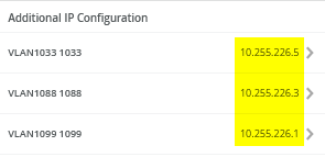
Here are screenshots after the configuration has been done:
.
.
.
.
.
.
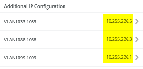
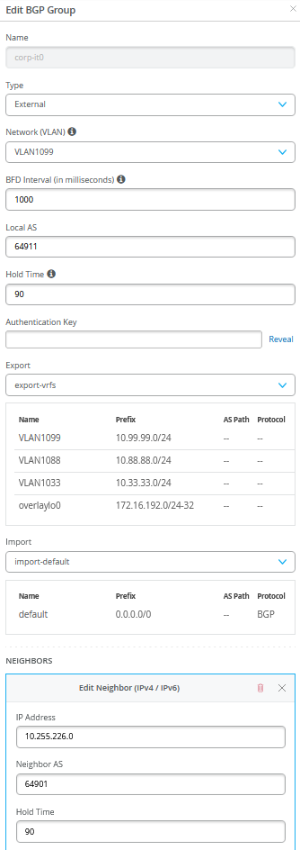
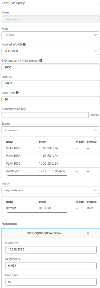
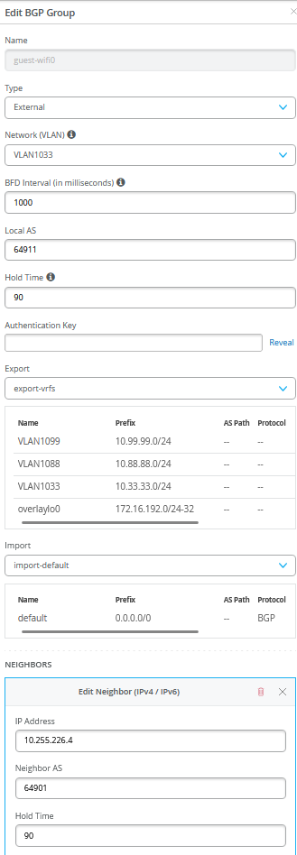
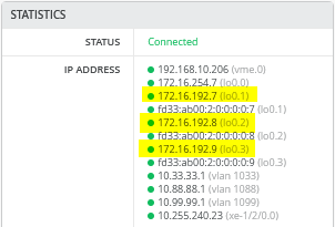
Configuration of service2 Block Switch for WAN Router Integration
We have a verbal description of what needs to be configured on this system here:
# configure the Additional IP-Subnet 10.255.226.1 255.255.255.254 to Network/VLAN:VLAN1099
# configure the Additional IP-Subnet 10.255.226.3 255.255.255.254 to Network/VLAN:VLAN1088
# configure the Additional IP-Subnet 10.255.226.5 255.255.255.254 to Network/VLAN:VLAN1033
# Then bind these 3 Network/VLANs to Port Interface xe-0/0/36 as L3-Sub-Interfaces with MTU=9018
.
# Enable BGP and create an Export policy called 'export-vrfs'
# Add to this export Policy the following Networks as:
# - Add Term w. Name=VLAN1099  Prefix=10.99.99.0/24  Protocol=None  Then=Accept
# - Add Term w. Name=VLAN1088  Prefix=10.88.88.0/24  Protocol=None  Then=Accept
# - Add Term w. Name=VLAN1033  Prefix=10.33.33.0/24  Protocol=None  Then=Accept
# - Add Term w. Name=overlaylo0 Prefix=172.16.192.0/24-32  Protocol=None  Then=Accept
.
# Create an Export policy called 'import-default'
# - Name=default  Prefix=0.0.0.0/0  Protocol=BGP  Action=Accept
.
# Create a BGP Group with:
# - Name=corp-it0
# - Type=External
# - Network (VLAN)=VLAN1099
# - BFD interval=1000
# - Local AS=64911
# - Hold Time=90
# - Set Export=export-vrfs and Import=import-default
# Add also the following Neighbor
# - IP_Address=10.255.226.0  Neighbor_AS=64901  Hold-Time=90
.
# Create a BGP Group with:
# - Name=developers0
# - Type=External
# - Network (VLAN)=VLAN1088
# - BFD interval=1000
# - Local AS=64911
# - Hold Time=90
# - Set Export=export-vrfs and Import=import-default
# Add also the following Neighbor
# - IP_Address=10.255.226.2  Neighbor_AS=64901  Hold-Time=90
.
# Create a BGP Group with:
# - Name=guest-wifi0
# - Type=External
# - Network (VLAN)=VLAN1033
# - BFD interval=1000
# - Local AS=64911
# - Hold Time=90
# - Set Export=export-vrfs and Import=import-default
# Add also the following Neighbor
# - IP_Address=10.255.226.4  Neighbor_AS=64901  Hold-Time=90
Here are screenshots after the configuration is done:
.
.png)
.
.png)
.
.
.
.png)
Verification Between Service Block Switches and WAN-Router After Integration
This step assumes you have also configured the WAN-Router to bring up the BGP route exchanges.
Service1 Switch:
Service1 switch must have established BGP peering with all three peers and obtained a default route from WAN-Router for each of the three VRF’s.
root@service1> show bgp summary
Threading mode: BGP I/O
Default eBGP mode: advertise - accept, receive - accept
Groups: 5 Peers: 7 Down peers: 0
Table          Tot Paths  Act Paths Suppressed    History Damp State    Pending
inet.0
                      13         11          0          0          0          0
bgp.evpn.0
                     102         56          0          0          0          0
Peer                     AS      InPkt     OutPkt    OutQ   Flaps Last Up/Dwn State|#Active/Received/Accepted/Damped...
10.255.224.0          64901        141        143       0       1     1:02:40 Establ
  corp-it.inet.0: 1/1/1/0
10.255.224.2          64901        140        141       0       1     1:02:36 Establ
  developers.inet.0: 1/1/1/0
10.255.224.4          64901        140        141       0       1     1:02:32 Establ
  guest-wifi.inet.0: 1/1/1/0
10.255.240.3          65003       3110       3139       0       0    23:45:45 Establ
  inet.0: 6/7/7/0
10.255.240.5          65004       3127       3148       0       0    23:45:44 Establ
  inet.0: 5/6/6/0
172.16.254.3          65003       5337       5143       0       0    23:45:44 Establ
  bgp.evpn.0: 30/56/56/0
  default-switch.evpn.0: 10/21/21/0
  __default_evpn__.evpn.0: 0/0/0/0
  guest-wifi.evpn.0: 10/10/10/0
  developers.evpn.0: 12/12/12/0
  corp-it.evpn.0: 13/13/13/0
172.16.254.4          65004       6069       4393       0       0    23:45:43 Establ
  bgp.evpn.0: 26/46/46/0
  default-switch.evpn.0: 11/21/21/0
  __default_evpn__.evpn.0: 0/0/0/0
  guest-wifi.evpn.0: 0/7/7/0
  developers.evpn.0: 0/9/9/0
  corp-it.evpn.0: 0/9/9/0
.
root@service1> show bfd session
                                                  Detect   Transmit
Address                  State     Interface      Time     Interval  Multiplier
10.255.224.0             Up        xe-0/0/36.1099 3.000     1.000        3
10.255.224.2             Up        xe-0/0/36.1088 3.000     1.000        3
10.255.224.4             Up        xe-0/0/36.1033 3.000     1.000        3
10.255.240.3             Up        et-0/0/52.0    3.000     1.000        3
10.255.240.5             Up        et-0/0/53.0    3.000     1.000        3
172.16.254.3             Up                       3.000     1.000        3
172.16.254.4             Up                       3.000     1.000        3
.
7 sessions, 7 clients
Cumulative transmit rate 7.0 pps, cumulative receive rate 7.0 pps
.
root@service1> show route table corp-it.inet.0
corp-it.inet.0: 12 destinations, 15 routes (12 active, 0 holddown, 0 hidden)
@ = Routing Use Only, # = Forwarding Use Only
+ = Active Route, - = Last Active, * = Both
.
0.0.0.0/0          *[BGP/170] 01:00:16, localpref 100
                      AS path: 64901 I, validation-state: unverified
                    >  to 10.255.224.0 via xe-0/0/36.1099
                    [EVPN/170] 01:00:15
                    >  to 10.255.240.3 via et-0/0/52.0
10.99.99.0/24      @[EVPN/170] 02:22:25
                       to 10.255.240.3 via et-0/0/52.0
                    >  to 10.255.240.5 via et-0/0/53.0
                    [EVPN/170] 02:22:25
                       to 10.255.240.3 via et-0/0/52.0
                    >  to 10.255.240.5 via et-0/0/53.0
                   #[Multipath/255] 02:22:25, metric2 0
                       to 10.255.240.3 via et-0/0/52.0
                    >  to 10.255.240.5 via et-0/0/53.0
                       to 10.255.240.3 via et-0/0/52.0
                    >  to 10.255.240.5 via et-0/0/53.0
10.99.99.23/32     *[EVPN/170] 02:22:25
                       to 10.255.240.3 via et-0/0/52.0
                    >  to 10.255.240.5 via et-0/0/53.0
10.99.99.42/32     *[EVPN/170] 02:22:25
                    >  to 10.255.240.3 via et-0/0/52.0
                       to 10.255.240.5 via et-0/0/53.0
10.99.99.99/32     *[EVPN/170] 02:22:25
                       to 10.255.240.3 via et-0/0/52.0
                    >  to 10.255.240.5 via et-0/0/53.0
10.255.224.0/31    *[Direct/0] 02:22:25
                    >  via xe-0/0/36.1099
10.255.224.1/32    *[Local/0] 02:22:25
                       Local via xe-0/0/36.1099
10.255.226.0/31    *[EVPN/170] 02:22:21
                    >  to 10.255.240.3 via et-0/0/52.0
172.16.192.1/32    *[Direct/0] 02:22:25
                    >  via lo0.1
172.16.192.4/32    *[EVPN/170] 02:22:25
                       to 10.255.240.3 via et-0/0/52.0
                    >  to 10.255.240.5 via et-0/0/53.0
172.16.192.7/32    *[EVPN/170] 02:22:25
                       to 10.255.240.3 via et-0/0/52.0
                    >  to 10.255.240.5 via et-0/0/53.0
172.16.192.10/32   *[EVPN/170] 02:22:21
                    >  to 10.255.240.3 via et-0/0/52.0
.
root@service1> show route table developers.inet.0
developers.inet.0: 11 destinations, 14 routes (11 active, 0 holddown, 0 hidden)
@ = Routing Use Only, # = Forwarding Use Only
+ = Active Route, - = Last Active, * = Both
.
0.0.0.0/0          *[BGP/170] 01:00:32, localpref 100
                      AS path: 64901 I, validation-state: unverified
                    >  to 10.255.224.2 via xe-0/0/36.1088
                    [EVPN/170] 01:00:31
                    >  to 10.255.240.3 via et-0/0/52.0
10.88.88.0/24      @[EVPN/170] 02:22:45
                       to 10.255.240.3 via et-0/0/52.0
                    >  to 10.255.240.5 via et-0/0/53.0
                    [EVPN/170] 02:22:45
                       to 10.255.240.3 via et-0/0/52.0
                    >  to 10.255.240.5 via et-0/0/53.0
                   #[Multipath/255] 02:22:45, metric2 0
                       to 10.255.240.3 via et-0/0/52.0
                    >  to 10.255.240.5 via et-0/0/53.0
                       to 10.255.240.3 via et-0/0/52.0
                    >  to 10.255.240.5 via et-0/0/53.0
10.88.88.23/32     *[EVPN/170] 02:22:45
                       to 10.255.240.3 via et-0/0/52.0
                    >  to 10.255.240.5 via et-0/0/53.0
10.88.88.88/32     *[EVPN/170] 02:22:45
                    >  to 10.255.240.3 via et-0/0/52.0
                       to 10.255.240.5 via et-0/0/53.0
10.255.224.2/31    *[Direct/0] 02:22:45
                    >  via xe-0/0/36.1088
10.255.224.3/32    *[Local/0] 02:22:45
                       Local via xe-0/0/36.1088
10.255.226.2/31    *[EVPN/170] 02:22:41
                    >  to 10.255.240.3 via et-0/0/52.0
172.16.192.2/32    *[Direct/0] 02:22:45
                    >  via lo0.2
172.16.192.5/32    *[EVPN/170] 02:22:45
                       to 10.255.240.3 via et-0/0/52.0
                    >  to 10.255.240.5 via et-0/0/53.0
172.16.192.8/32    *[EVPN/170] 02:22:45
                    >  to 10.255.240.3 via et-0/0/52.0
                       to 10.255.240.5 via et-0/0/53.0
172.16.192.11/32   *[EVPN/170] 02:22:41
                    >  to 10.255.240.3 via et-0/0/52.0
.
root@service1> show route table guest-wifi.inet.0
guest-wifi.inet.0: 9 destinations, 12 routes (9 active, 0 holddown, 0 hidden)
@ = Routing Use Only, # = Forwarding Use Only
+ = Active Route, - = Last Active, * = Both
.
0.0.0.0/0          *[BGP/170] 01:00:45, localpref 100
                      AS path: 64901 I, validation-state: unverified
                    >  to 10.255.224.4 via xe-0/0/36.1033
                    [EVPN/170] 01:00:44
                    >  to 10.255.240.3 via et-0/0/52.0
10.33.33.0/24      @[EVPN/170] 02:23:02
                       to 10.255.240.3 via et-0/0/52.0
                    >  to 10.255.240.5 via et-0/0/53.0
                    [EVPN/170] 02:23:02
                       to 10.255.240.3 via et-0/0/52.0
                    >  to 10.255.240.5 via et-0/0/53.0
                   #[Multipath/255] 02:23:02, metric2 0
                       to 10.255.240.3 via et-0/0/52.0
                    >  to 10.255.240.5 via et-0/0/53.0
                       to 10.255.240.3 via et-0/0/52.0
                    >  to 10.255.240.5 via et-0/0/53.0
10.255.224.4/31    *[Direct/0] 02:23:02
                    >  via xe-0/0/36.1033
10.255.224.5/32    *[Local/0] 02:23:02
                       Local via xe-0/0/36.1033
10.255.226.4/31    *[EVPN/170] 02:22:58
                    >  to 10.255.240.3 via et-0/0/52.0
172.16.192.3/32    *[Direct/0] 02:23:02
                    >  via lo0.3
172.16.192.6/32    *[EVPN/170] 02:23:02
                       to 10.255.240.3 via et-0/0/52.0
                    >  to 10.255.240.5 via et-0/0/53.0
172.16.192.9/32    *[EVPN/170] 02:23:02
                    >  to 10.255.240.3 via et-0/0/52.0
                       to 10.255.240.5 via et-0/0/53.0
172.16.192.12/32   *[EVPN/170] 02:22:58
                    >  to 10.255.240.3 via et-0/0/52.0
Service2 Switch:
Service2 switch must have established BGP peering with all three peers and obtained a default route from WAN-Router for each of the three VRFs.
Remember that we have a simulated broken Link still between service2 and core2. That is what we lesser routes and bfd sessions.
root@service2> show bgp summary
Threading mode: BGP I/O
Default eBGP mode: advertise - accept, receive - accept
Groups: 5 Peers: 7 Down peers: 2
Table          Tot Paths  Act Paths Suppressed    History Damp State    Pending
inet.0
                       7          7          0          0          0          0
bgp.evpn.0
                      57         57          0          0          0          0
Peer                     AS      InPkt     OutPkt    OutQ   Flaps Last Up/Dwn State|#Active/Received/Accepted/Damped...
10.255.226.0          64901        160        163       0       1     1:11:18 Establ
  corp-it.inet.0: 1/1/1/0
10.255.226.2          64901        159        161       0       1     1:11:14 Establ
  developers.inet.0: 1/1/1/0
10.255.226.4          64901        159        162       0       1     1:11:10 Establ
  guest-wifi.inet.0: 1/1/1/0
10.255.240.7          65003       3129       3179       0       0    23:54:22 Establ
  inet.0: 7/7/7/0
10.255.240.9          65004          0          0       0       0    23:55:54 Idle
172.16.254.3          65003       6035       3203       0       0    23:54:20 Establ
  bgp.evpn.0: 57/57/57/0
  default-switch.evpn.0: 22/22/22/0
  __default_evpn__.evpn.0: 0/0/0/0
  guest-wifi.evpn.0: 10/10/10/0
  developers.evpn.0: 12/12/12/0
  corp-it.evpn.0: 13/13/13/0
172.16.254.4          65004          0          0       0       0    23:55:54 Active
.
root@service2> show bfd session
                                                  Detect   Transmit
Address                  State     Interface      Time     Interval  Multiplier
10.255.226.0             Up        xe-0/0/36.1099 3.000     1.000        3
10.255.226.2             Up        xe-0/0/36.1088 3.000     1.000        3
10.255.226.4             Up        xe-0/0/36.1033 3.000     1.000        3
10.255.240.7             Up        et-0/0/53.0    3.000     1.000        3
172.16.254.3             Up                       3.000     1.000        3
.
5 sessions, 5 clients
Cumulative transmit rate 5.0 pps, cumulative receive rate 5.0 pps
.
root@service2> show route table corp-it.inet.0
corp-it.inet.0: 12 destinations, 15 routes (12 active, 0 holddown, 0 hidden)
@ = Routing Use Only, # = Forwarding Use Only
+ = Active Route, - = Last Active, * = Both
.
0.0.0.0/0          *[BGP/170] 01:12:36, localpref 100
                      AS path: 64901 I, validation-state: unverified
                    >  to 10.255.226.0 via xe-0/0/36.1099
                    [EVPN/170] 01:12:36
                    >  to 10.255.240.7 via et-0/0/53.0
10.99.99.0/24      @[EVPN/170] 02:34:43
                    >  to 10.255.240.7 via et-0/0/53.0
                    [EVPN/170] 02:34:43
                    >  to 10.255.240.7 via et-0/0/53.0
                   #[Multipath/255] 02:34:43, metric2 0
                    >  to 10.255.240.7 via et-0/0/53.0
                    >  to 10.255.240.7 via et-0/0/53.0
10.99.99.23/32     *[EVPN/170] 02:34:43
                    >  to 10.255.240.7 via et-0/0/53.0
10.99.99.42/32     *[EVPN/170] 02:34:43
                    >  to 10.255.240.7 via et-0/0/53.0
10.99.99.99/32     *[EVPN/170] 02:34:43
                    >  to 10.255.240.7 via et-0/0/53.0
10.255.224.0/31    *[EVPN/170] 02:34:43
                    >  to 10.255.240.7 via et-0/0/53.0
10.255.226.0/31    *[Direct/0] 02:34:42
                    >  via xe-0/0/36.1099
10.255.226.1/32    *[Local/0] 02:34:42
                       Local via xe-0/0/36.1099
172.16.192.1/32    *[EVPN/170] 02:34:43
                    >  to 10.255.240.7 via et-0/0/53.0
172.16.192.4/32    *[EVPN/170] 02:34:43
                    >  to 10.255.240.7 via et-0/0/53.0
172.16.192.7/32    *[EVPN/170] 02:34:43
                    >  to 10.255.240.7 via et-0/0/53.0
172.16.192.10/32   *[Direct/0] 02:34:42
                    >  via lo0.1
.
root@service2> show route table developers.inet.0
developers.inet.0: 11 destinations, 14 routes (11 active, 0 holddown, 0 hidden)
@ = Routing Use Only, # = Forwarding Use Only
+ = Active Route, - = Last Active, * = Both
.
0.0.0.0/0          *[BGP/170] 01:12:45, localpref 100
                      AS path: 64901 I, validation-state: unverified
                    >  to 10.255.226.2 via xe-0/0/36.1088
                    [EVPN/170] 01:12:45
                    >  to 10.255.240.7 via et-0/0/53.0
10.88.88.0/24      @[EVPN/170] 02:34:56
                    >  to 10.255.240.7 via et-0/0/53.0
                    [EVPN/170] 02:34:56
                    >  to 10.255.240.7 via et-0/0/53.0
                   #[Multipath/255] 02:34:56, metric2 0
                    >  to 10.255.240.7 via et-0/0/53.0
                    >  to 10.255.240.7 via et-0/0/53.0
10.88.88.23/32     *[EVPN/170] 02:34:56
                    >  to 10.255.240.7 via et-0/0/53.0
10.88.88.88/32     *[EVPN/170] 02:34:56
                    >  to 10.255.240.7 via et-0/0/53.0
10.255.224.2/31    *[EVPN/170] 02:34:56
                    >  to 10.255.240.7 via et-0/0/53.0
10.255.226.2/31    *[Direct/0] 02:34:55
                    >  via xe-0/0/36.1088
10.255.226.3/32    *[Local/0] 02:34:55
                       Local via xe-0/0/36.1088
172.16.192.2/32    *[EVPN/170] 02:34:56
                    >  to 10.255.240.7 via et-0/0/53.0
172.16.192.5/32    *[EVPN/170] 02:34:56
                    >  to 10.255.240.7 via et-0/0/53.0
172.16.192.8/32    *[EVPN/170] 02:34:56
                    >  to 10.255.240.7 via et-0/0/53.0
172.16.192.11/32   *[Direct/0] 02:34:55
                    >  via lo0.2
.
root@service2> show route table guest-wifi.inet.0
guest-wifi.inet.0: 9 destinations, 12 routes (9 active, 0 holddown, 0 hidden)
@ = Routing Use Only, # = Forwarding Use Only
+ = Active Route, - = Last Active, * = Both
.
0.0.0.0/0          *[BGP/170] 01:12:57, localpref 100
                      AS path: 64901 I, validation-state: unverified
                    >  to 10.255.226.4 via xe-0/0/36.1033
                    [EVPN/170] 01:12:57
                    >  to 10.255.240.7 via et-0/0/53.0
10.33.33.0/24      @[EVPN/170] 02:35:12
                    >  to 10.255.240.7 via et-0/0/53.0
                    [EVPN/170] 02:35:12
                    >  to 10.255.240.7 via et-0/0/53.0
                   #[Multipath/255] 02:35:12, metric2 0
                    >  to 10.255.240.7 via et-0/0/53.0
                    >  to 10.255.240.7 via et-0/0/53.0
10.255.224.4/31    *[EVPN/170] 02:35:12
                    >  to 10.255.240.7 via et-0/0/53.0
10.255.226.4/31    *[Direct/0] 02:35:11
                    >  via xe-0/0/36.1033
10.255.226.5/32    *[Local/0] 02:35:11
                       Local via xe-0/0/36.1033
172.16.192.3/32    *[EVPN/170] 02:35:12
                    >  to 10.255.240.7 via et-0/0/53.0
172.16.192.6/32    *[EVPN/170] 02:35:12
                    >  to 10.255.240.7 via et-0/0/53.0
172.16.192.9/32    *[EVPN/170] 02:35:12
                    >  to 10.255.240.7 via et-0/0/53.0
172.16.192.12/32   *[Direct/0] 02:35:11
                    >  via lo0.3
WAN-Router:
Below we captured the BGP and BFD summary as well as the routes known to the device. Important here are:
- Route
10.99.99.0/24from overlay=VLAN1099assigned to VRF=corp-it - Route
10.88.88.0/24from overlay=VLAN1088assigned to VRF=developers - Route
10.33.33.0/24from overlay=VLAN1033assigned to VRF=guest-wifi - Route
172.16.192.4to9/32from overlay for DHCP-Relay usage.
.
Review the below information
root@wanrouter> show bgp summary
Threading mode: BGP I/O
Default eBGP mode: advertise - accept, receive - accept
Groups: 3 Peers: 6 Down peers: 0
Peer                     AS      InPkt     OutPkt    OutQ   Flaps Last Up/Dwn State|#Active/Received/Accepted/Damped...
10.255.224.1          64911        145        140       0       2     1:02:47 Establ
  public-int.inet.0: 4/5/5/0
10.255.224.3          64911        144        140       0       2     1:02:51 Establ
  public-int.inet.0: 4/5/5/0
10.255.224.5          64911        143        140       0       6     1:02:46 Establ
  public-int.inet.0: 4/5/5/0
10.255.226.1          64911        145        140       0       2     1:02:44 Establ
  public-int.inet.0: 4/5/5/0
10.255.226.3          64911        145        140       0       2     1:02:48 Establ
  public-int.inet.0: 4/5/5/0
10.255.226.5          64911        144        141       0       6     1:02:51 Establ
  public-int.inet.0: 4/5/5/0
.
root@wanrouter> show bfd session
                                                  Detect   Transmit
Address                  State     Interface      Time     Interval  Multiplier
10.255.224.1             Up        xe-0/0/16.1099 3.000     1.000        3
10.255.224.3             Up        xe-0/0/16.1088 3.000     1.000        3
10.255.224.5             Up        xe-0/0/16.1033 3.000     1.000        3
10.255.226.1             Up        xe-0/0/17.1099 3.000     1.000        3
10.255.226.3             Up        xe-0/0/17.1088 3.000     1.000        3
10.255.226.5             Up        xe-0/0/17.1033 3.000     1.000        3
.
6 sessions, 6 clients
Cumulative transmit rate 6.0 pps, cumulative receive rate 6.0 pps
.
root@wanrouter> show route
              public-int.inet.0: 30 destinations, 45 routes (30 active, 0 holddown, 0 hidden)
+ = Active Route, - = Last Active, * = Both
.
0.0.0.0/0          *[Static/5] 5d 23:56:46
                    >  to 192.168.10.1 via ge-0/0/0.0
10.33.33.0/24      *[BGP/170] 01:03:06, localpref 100, from 10.255.226.5
                      AS path: 64911 65002 65003 65006 65007 I, validation-state: unverified
                       to 10.255.226.5 via xe-0/0/17.1033
                    >  to 10.255.224.5 via xe-0/0/16.1033
                    [BGP/170] 01:03:16, localpref 100
                      AS path: 64911 65001 65003 65006 65007 I, validation-state: unverified
                    >  to 10.255.224.5 via xe-0/0/16.1033
10.88.88.0/24      *[BGP/170] 01:03:06, localpref 100, from 10.255.224.3
                      AS path: 64911 65001 65003 65006 65007 I, validation-state: unverified
                       to 10.255.224.3 via xe-0/0/16.1088
                    >  to 10.255.226.3 via xe-0/0/17.1088
                    [BGP/170] 01:03:18, localpref 100
                      AS path: 64911 65002 65003 65006 65007 I, validation-state: unverified
                    >  to 10.255.226.3 via xe-0/0/17.1088
10.99.99.0/24      *[BGP/170] 01:03:06, localpref 100, from 10.255.224.1
                      AS path: 64911 65001 65003 65006 65007 I, validation-state: unverified
                       to 10.255.224.1 via xe-0/0/16.1099
                    >  to 10.255.226.1 via xe-0/0/17.1099
                    [BGP/170] 01:03:14, localpref 100
                      AS path: 64911 65002 65003 65006 65007 I, validation-state: unverified
                    >  to 10.255.226.1 via xe-0/0/17.1099
10.255.224.0/31    *[Direct/0] 22:24:32
                    >  via xe-0/0/16.1099
10.255.224.0/32    *[Local/0] 22:24:32
                       Local via xe-0/0/16.1099
10.255.224.2/31    *[Direct/0] 22:24:32
                    >  via xe-0/0/16.1088
10.255.224.2/32    *[Local/0] 22:24:32
                       Local via xe-0/0/16.1088
10.255.224.4/31    *[Direct/0] 22:24:32
                    >  via xe-0/0/16.1033
10.255.224.4/32    *[Local/0] 22:24:32
                       Local via xe-0/0/16.1033
10.255.226.0/31    *[Direct/0] 22:24:32
                    >  via xe-0/0/17.1099
10.255.226.0/32    *[Local/0] 22:24:32
                       Local via xe-0/0/17.1099
10.255.226.2/31    *[Direct/0] 22:24:32
                    >  via xe-0/0/17.1088
10.255.226.2/32    *[Local/0] 22:24:32
                       Local via xe-0/0/17.1088
10.255.226.4/31    *[Direct/0] 22:24:32
                    >  via xe-0/0/17.1033
10.255.226.4/32    *[Local/0] 22:24:32
                       Local via xe-0/0/17.1033
172.16.192.1/32    *[BGP/170] 01:03:17, localpref 100
                      AS path: 64911 I, validation-state: unverified
                    >  to 10.255.224.1 via xe-0/0/16.1099
                    [BGP/170] 01:03:14, localpref 100
                      AS path: 64911 65002 65003 65001 I, validation-state: unverified
                    >  to 10.255.226.1 via xe-0/0/17.1099
172.16.192.2/32    *[BGP/170] 01:03:21, localpref 100
                      AS path: 64911 I, validation-state: unverified
                    >  to 10.255.224.3 via xe-0/0/16.1088
                    [BGP/170] 01:03:18, localpref 100
                      AS path: 64911 65002 65003 65001 I, validation-state: unverified
                    >  to 10.255.226.3 via xe-0/0/17.1088
172.16.192.3/32    *[BGP/170] 01:03:16, localpref 100
                      AS path: 64911 I, validation-state: unverified
                    >  to 10.255.224.5 via xe-0/0/16.1033
                    [BGP/170] 01:03:22, localpref 100
                      AS path: 64911 65002 65003 65001 I, validation-state: unverified
                    >  to 10.255.226.5 via xe-0/0/17.1033
172.16.192.4/32    *[BGP/170] 01:03:06, localpref 100, from 10.255.224.1
                      AS path: 64911 65001 65003 65005 65008 I, validation-state: unverified
                       to 10.255.224.1 via xe-0/0/16.1099
                    >  to 10.255.226.1 via xe-0/0/17.1099
                    [BGP/170] 01:03:14, localpref 100
                      AS path: 64911 65002 65003 65005 65008 I, validation-state: unverified
                    >  to 10.255.226.1 via xe-0/0/17.1099
172.16.192.5/32    *[BGP/170] 01:03:06, localpref 100, from 10.255.224.3
                      AS path: 64911 65001 65003 65005 65008 I, validation-state: unverified
                       to 10.255.224.3 via xe-0/0/16.1088
                    >  to 10.255.226.3 via xe-0/0/17.1088
                    [BGP/170] 01:03:18, localpref 100
                      AS path: 64911 65002 65003 65005 65008 I, validation-state: unverified
                    >  to 10.255.226.3 via xe-0/0/17.1088
172.16.192.6/32    *[BGP/170] 01:03:06, localpref 100, from 10.255.226.5
                      AS path: 64911 65002 65003 65006 65008 I, validation-state: unverified
                       to 10.255.226.5 via xe-0/0/17.1033
                    >  to 10.255.224.5 via xe-0/0/16.1033
                    [BGP/170] 01:03:16, localpref 100
                      AS path: 64911 65001 65003 65006 65008 I, validation-state: unverified
                    >  to 10.255.224.5 via xe-0/0/16.1033
172.16.192.7/32    *[BGP/170] 01:03:06, localpref 100, from 10.255.224.1
                      AS path: 64911 65001 65003 65005 65007 I, validation-state: unverified
                       to 10.255.224.1 via xe-0/0/16.1099
                    >  to 10.255.226.1 via xe-0/0/17.1099
                    [BGP/170] 01:03:14, localpref 100
                      AS path: 64911 65002 65003 65005 65007 I, validation-state: unverified
                    >  to 10.255.226.1 via xe-0/0/17.1099
172.16.192.8/32    *[BGP/170] 01:03:06, localpref 100
                      AS path: 64911 65001 65003 65006 65007 I, validation-state: unverified
                    >  to 10.255.224.3 via xe-0/0/16.1088
                       to 10.255.226.3 via xe-0/0/17.1088
                    [BGP/170] 01:03:18, localpref 100
                      AS path: 64911 65002 65003 65006 65007 I, validation-state: unverified
                    >  to 10.255.226.3 via xe-0/0/17.1088
172.16.192.9/32    *[BGP/170] 01:03:06, localpref 100
                      AS path: 64911 65002 65003 65006 65007 I, validation-state: unverified
                    >  to 10.255.226.5 via xe-0/0/17.1033
                       to 10.255.224.5 via xe-0/0/16.1033
                    [BGP/170] 01:03:16, localpref 100
                      AS path: 64911 65001 65003 65006 65007 I, validation-state: unverified
                    >  to 10.255.224.5 via xe-0/0/16.1033
172.16.192.10/32   *[BGP/170] 01:03:14, localpref 100
                      AS path: 64911 I, validation-state: unverified
                    >  to 10.255.226.1 via xe-0/0/17.1099
                    [BGP/170] 01:03:17, localpref 100
                      AS path: 64911 65001 65003 65002 I, validation-state: unverified
                    >  to 10.255.224.1 via xe-0/0/16.1099
172.16.192.11/32   *[BGP/170] 01:03:18, localpref 100
                      AS path: 64911 I, validation-state: unverified
                    >  to 10.255.226.3 via xe-0/0/17.1088
                    [BGP/170] 01:03:21, localpref 100
                      AS path: 64911 65001 65003 65002 I, validation-state: unverified
                    >  to 10.255.224.3 via xe-0/0/16.1088
172.16.192.12/32   *[BGP/170] 01:03:22, localpref 100
                      AS path: 64911 I, validation-state: unverified
                    >  to 10.255.226.5 via xe-0/0/17.1033
                    [BGP/170] 01:03:16, localpref 100
                      AS path: 64911 65001 65003 65002 I, validation-state: unverified
                    >  to 10.255.224.5 via xe-0/0/16.1033
192.168.10.0/24    *[Direct/0] 6d 00:00:22
                    >  via ge-0/0/0.0
192.168.10.99/32   *[Local/0] 6d 00:00:22
                       Local via ge-0/0/0.0
Fabric VRF Route Updates
Now that we exchange routes with the WAN-Router, all Access
Switches should have default routes obtained via the service block
switches. In our example we review VRF corp-it on
access1 switch to see the difference between before and after
WAN-Router integration.
root@access1> show route table corp-it.inet.0
corp-it.inet.0: 12 destinations, 15 routes (12 active, 0 holddown, 0 hidden)
@ = Routing Use Only, # = Forwarding Use Only
+ = Active Route, - = Last Active, * = Both
0.0.0.0/0          @[EVPN/170] 00:02:34
                    >  to 10.255.240.24 via mge-0/0/36.0
                       to 10.255.240.20 via mge-0/0/37.0
                    [EVPN/170] 00:02:30
                    >  to 10.255.240.24 via mge-0/0/36.0
                       to 10.255.240.20 via mge-0/0/37.0
                   #[Multipath/255] 00:02:30, metric2 0
                    >  to 10.255.240.24 via mge-0/0/36.0
                       to 10.255.240.20 via mge-0/0/37.0
                    >  to 10.255.240.24 via mge-0/0/36.0
                       to 10.255.240.20 via mge-0/0/37.0
10.99.99.0/24      *[Direct/0] 04:00:31
                    >  via irb.1099
                    [EVPN/170] 03:53:25
                       to 10.255.240.24 via mge-0/0/36.0
                    >  to 10.255.240.20 via mge-0/0/37.0
10.99.99.1/32      *[Local/0] 04:00:31
                       Local via irb.1099
10.99.99.23/32     *[EVPN/7] 03:47:48
                    >  via irb.1099
10.99.99.42/32     *[EVPN/170] 03:49:02
                    >  to 10.255.240.24 via mge-0/0/36.0
                       to 10.255.240.20 via mge-0/0/37.0
10.99.99.99/32     *[EVPN/7] 03:45:21
                    >  via irb.1099
10.255.224.0/31    *[EVPN/170] 00:02:44
                    >  to 10.255.240.24 via mge-0/0/36.0
                       to 10.255.240.20 via mge-0/0/37.0
10.255.226.0/31    *[EVPN/170] 00:02:41
                    >  to 10.255.240.24 via mge-0/0/36.0
                       to 10.255.240.20 via mge-0/0/37.0
172.16.192.1/32    *[EVPN/170] 00:02:44
                       to 10.255.240.24 via mge-0/0/36.0
                    >  to 10.255.240.20 via mge-0/0/37.0
172.16.192.4/32    *[Direct/0] 04:00:32
                    >  via lo0.1
172.16.192.7/32    *[EVPN/170] 03:53:25
                       to 10.255.240.24 via mge-0/0/36.0
                    >  to 10.255.240.20 via mge-0/0/37.0
172.16.192.10/32   *[EVPN/170] 00:02:41
                    >  to 10.255.240.24 via mge-0/0/36.0
                       to 10.255.240.20 via mge-0/0/37.0
Client Communication Verification Repeated
The final test now is to repeat the client communication verification that we have performed here: Wired Client Verification. In contrast we can now ping clients in other VRFs as the WAN router hair-pins this traffic, communication to Internet is now possible and we also can obtain DHCP-Leases.
root@desktop1:~# ifconfig ens5
ens5: flags=4163<UP,BROADCAST,RUNNING,MULTICAST>  mtu 1500
        inet 10.99.99.99  netmask 255.255.255.0  broadcast 10.99.99.255
        inet6 fe80::5054:ff:fe7e:f9b1  prefixlen 64  scopeid 0x20<link>
        ether 52:54:00:7e:f9:b1  txqueuelen 1000  (Ethernet)
        RX packets 170291  bytes 424870428 (424.8 MB)
        RX errors 0  dropped 99974  overruns 0  frame 0
        TX packets 29012  bytes 1942778 (1.9 MB)
        TX errors 0  dropped 0 overruns 0  carrier 0  collisions 0
.
root@desktop1:~# ip r
              default via 10.99.99.1 dev ens5 proto static
10.99.99.0/24 dev ens5 proto kernel scope link src 10.99.99.99
192.168.10.0/24 dev ens3 proto kernel scope link src 192.168.10.61
.
root@desktop1:~# ping -c3 10.99.99.1
PING 10.99.99.1 (10.99.99.1) 56(84) bytes of data.
64 bytes from 10.99.99.1: icmp_seq=1 ttl=64 time=8.70 ms
64 bytes from 10.99.99.1: icmp_seq=2 ttl=64 time=7.06 ms
64 bytes from 10.99.99.1: icmp_seq=3 ttl=64 time=3.43 ms
.
root@desktop1:~# ping -c3 10.99.99.23
PING 10.99.99.23 (10.99.99.23) 56(84) bytes of data.
64 bytes from 10.99.99.23: icmp_seq=1 ttl=64 time=0.566 ms
64 bytes from 10.99.99.23: icmp_seq=2 ttl=64 time=0.531 ms
64 bytes from 10.99.99.23: icmp_seq=3 ttl=64 time=0.737 ms
.
root@desktop1:~# ping -c3 10.99.99.42
PING 10.99.99.42 (10.99.99.42) 56(84) bytes of data.
64 bytes from 10.99.99.42: icmp_seq=1 ttl=64 time=0.799 ms
64 bytes from 10.99.99.42: icmp_seq=2 ttl=64 time=0.532 ms
64 bytes from 10.99.99.42: icmp_seq=3 ttl=64 time=0.538 ms
.
root@desktop1:~# ping -c3 10.88.88.88
PING 10.88.88.88 (10.88.88.88) 56(84) bytes of data.
64 bytes from 10.88.88.88: icmp_seq=1 ttl=59 time=0.671 ms
64 bytes from 10.88.88.88: icmp_seq=2 ttl=59 time=0.576 ms
64 bytes from 10.88.88.88: icmp_seq=3 ttl=59 time=0.611 ms
.
root@desktop1:~# ping -c3 10.88.88.23
PING 10.88.88.23 (10.88.88.23) 56(84) bytes of data.
64 bytes from 10.88.88.23: icmp_seq=1 ttl=59 time=1.09 ms
64 bytes from 10.88.88.23: icmp_seq=2 ttl=59 time=0.645 ms
64 bytes from 10.88.88.23: icmp_seq=3 ttl=59 time=0.650 ms
.
root@desktop1:~# ping -c3 8.8.8.8
PING 8.8.8.8 (8.8.8.8) 56(84) bytes of data.
64 bytes from 8.8.8.8: icmp_seq=1 ttl=51 time=3.12 ms
64 bytes from 8.8.8.8: icmp_seq=2 ttl=51 time=3.03 ms
64 bytes from 8.8.8.8: icmp_seq=3 ttl=51 time=3.07 ms
.
root@desktop1:~# arp -an
? (10.99.99.1) at 00:00:5e:e4:31:57 [ether] on ens5
? (10.99.99.23) at 52:54:00:4a:e5:d0 [ether] on ens5
? (10.99.99.42) at 52:54:00:77:3c:03 [ether] on ens5
.
root@desktop1:~# dhclient -v ens5
Listening on LPF/ens5/52:54:00:7e:f9:b1
Sending on   LPF/ens5/52:54:00:7e:f9:b1
Sending on   Socket/fallback
DHCPDISCOVER on ens5 to 255.255.255.255 port 67 interval 3 (xid=0xefa2357a)
DHCPOFFER of 10.99.99.10 from 172.16.192.4
DHCPREQUEST for 10.99.99.10 on ens5 to 255.255.255.255 port 67 (xid=0x7a35a2ef)
DHCPACK of 10.99.99.10 from 172.16.192.4 (xid=0xefa2357a)
bound to 10.99.99.10 -- renewal in 765 seconds.