APPENDIX: IP Clos Fabric Verification (Optional)
This chapter is optional and can be skipped. It provides additional insight into the internal workings of the fabric for those interested in a deeper understanding.
The table below outlines what you will see within the fabric regarding wired clients using various commands.
| MAC-Address | Location | IP-Address | VLAN-ID | VRF | Interface | VTEP |
|---|---|---|---|---|---|---|
| 00:00:5e:e4:31:57 | access1+2 sw | 10.99.99.1 | 1099 | corp-it | irb.1099 | 172.16.254.7+8 |
| 52:54:00:4a:e5:d0 | Desktop5 VM | 10.99.99.23 | 1099 | corp-it | mge-0/0/11 | 172.16.254.8 |
| 52:54:00:77:3c:03 | Desktop4 VM | 10.99.99.42 | 1099 | corp-it | mge-3/0/13 | 172.16.254.7 |
| 52:54:00:7e:f9:b1 | Desktop1 VM | 10.99.99.99 | 1099 | corp-it | mge-0/0/14 | 172.16.254.8 |
| 00:00:5e:e4:31:57 | access1+2 sw | 10.88.88.1 | 1088 | developer | irb.1088 | 172.16.254.7+8 |
| 52:54:00:7c:77:40 | Desktop3 VM | 10.88.88.23 | 1088 | developer | mge-0/0/13 | 172.16.254.8 |
| 52:54:00:32:05:6f | Desktop2 VM | 10.88.88.88 | 1088 | developer | mge-3/0/12 | 172.16.254.7 |
| 00:00:5e:e4:31:57 | access1+2 sw | 10.33.33.1 | 1033 | guest-wifi | irb.1033 | 172.16.254.7+8 |
Wired Client Verification
Verification of the campus fabric IP Clos deployment. See Figure 1. Currently, there are five desktop VMs to validate the fabric with static IP address configuration. Let’s take a quick look to see if Desktop1 VM can connect internally and externally.
root@desktop1:~# ifconfig ens5
ens5: flags=4163<UP,BROADCAST,RUNNING,MULTICAST>  mtu 1500
        inet 10.99.99.99  netmask 255.255.255.0  broadcast 10.99.99.255
        inet6 fe80::5054:ff:fe7e:f9b1  prefixlen 64  scopeid 0x20<link>
        ether 52:54:00:7e:f9:b1  txqueuelen 1000  (Ethernet)
        RX packets 163054  bytes 424295446 (424.2 MB)
        RX errors 0  dropped 93549  overruns 0  frame 0
        TX packets 28662  bytes 1915505 (1.9 MB)
        TX errors 0  dropped 0 overruns 0  carrier 0  collisions 0
.
root@desktop1:~# ip r
              default via 10.99.99.1 dev ens5 proto static
10.99.99.0/24 dev ens5 proto kernel scope link src 10.99.99.99
192.168.10.0/24 dev ens3 proto kernel scope link src 192.168.10.61
.
root@desktop1:~# ping -c3 10.99.99.1
PING 10.99.99.1 (10.99.99.1) 56(84) bytes of data.
64 bytes from 10.99.99.1: icmp_seq=1 ttl=64 time=3.45 ms
64 bytes from 10.99.99.1: icmp_seq=2 ttl=64 time=8.16 ms
64 bytes from 10.99.99.1: icmp_seq=3 ttl=64 time=9.19 ms
.
root@desktop1:~# ping -c3 10.99.99.23
PING 10.99.99.23 (10.99.99.23) 56(84) bytes of data.
64 bytes from 10.99.99.23: icmp_seq=1 ttl=64 time=0.589 ms
64 bytes from 10.99.99.23: icmp_seq=2 ttl=64 time=0.447 ms
64 bytes from 10.99.99.23: icmp_seq=3 ttl=64 time=0.477 ms
.
root@desktop1:~# ping -c3 10.99.99.42
PING 10.99.99.42 (10.99.99.42) 56(84) bytes of data.
64 bytes from 10.99.99.42: icmp_seq=1 ttl=64 time=0.793 ms
64 bytes from 10.99.99.42: icmp_seq=2 ttl=64 time=0.565 ms
64 bytes from 10.99.99.42: icmp_seq=3 ttl=64 time=0.538 ms
.
root@desktop1:~# ping -c3 10.88.88.88
PING 10.88.88.88 (10.88.88.88) 56(84) bytes of data.
From 10.99.99.1 icmp_seq=1 Destination Net Unreachable
From 10.99.99.1 icmp_seq=2 Destination Net Unreachable
From 10.99.99.1 icmp_seq=3 Destination Net Unreachable
.
root@desktop1:~# ping -c3 10.88.88.23
PING 10.88.88.23 (10.88.88.23) 56(84) bytes of data.
From 10.99.99.1 icmp_seq=1 Destination Net Unreachable
From 10.99.99.1 icmp_seq=2 Destination Net Unreachable
From 10.99.99.1 icmp_seq=3 Destination Net Unreachable
.
root@desktop1:~# ping -c3 8.8.8.8
PING 8.8.8.8 (8.8.8.8) 56(84) bytes of data.
From 10.99.99.1 icmp_seq=1 Destination Net Unreachable
From 10.99.99.1 icmp_seq=2 Destination Net Unreachable
From 10.99.99.1 icmp_seq=3 Destination Net Unreachable
.
root@desktop1:~# arp -an
? (10.99.99.1) at 00:00:5e:e4:31:57 [ether] on ens5
? (10.99.99.23) at 52:54:00:4a:e5:d0 [ether] on ens5
? (10.99.99.42) at 52:54:00:77:3c:03 [ether] on ens5
.
root@desktop1:~# dhclient -v ens5
Listening on LPF/ens5/52:54:00:7e:f9:b1
Sending on   LPF/ens5/52:54:00:7e:f9:b1
Sending on   Socket/fallback
DHCPDISCOVER on ens5 to 255.255.255.255 port 67 interval 3 (xid=0x2358693f)
DHCPDISCOVER on ens5 to 255.255.255.255 port 67 interval 6 (xid=0x2358693f)
DHCPDISCOVER on ens5 to 255.255.255.255 port 67 interval 13 (xid=0x2358693f)
Validation steps:
- Confirmed local IP address, VLAN, and default gateway were configured on Desktop1 VM.
- Can ping default gateway—indicates that we can reach the access switch.
- Can ping Desktop5 VM in the same VLAN at the same switch.
- Can ping Desktop4 VM in the same VLAN at the other switch (access2 Virtual Chassis).
- Can not ping Desktop2 + 3 VM in different VRF. This is expected as there is isolation amongst VRFs in the fabric and we have not integrated the WAN router yet to hairpin that traffic.
- Can not ping the Internet. This is expected as we have not integrated the WAN router yet.
- ARP shows MAC addresses in Desktop1 VLAN reached to.
- No DHCP lease handouts. This is expected as our DHCP server is beyond the WAN router attached.
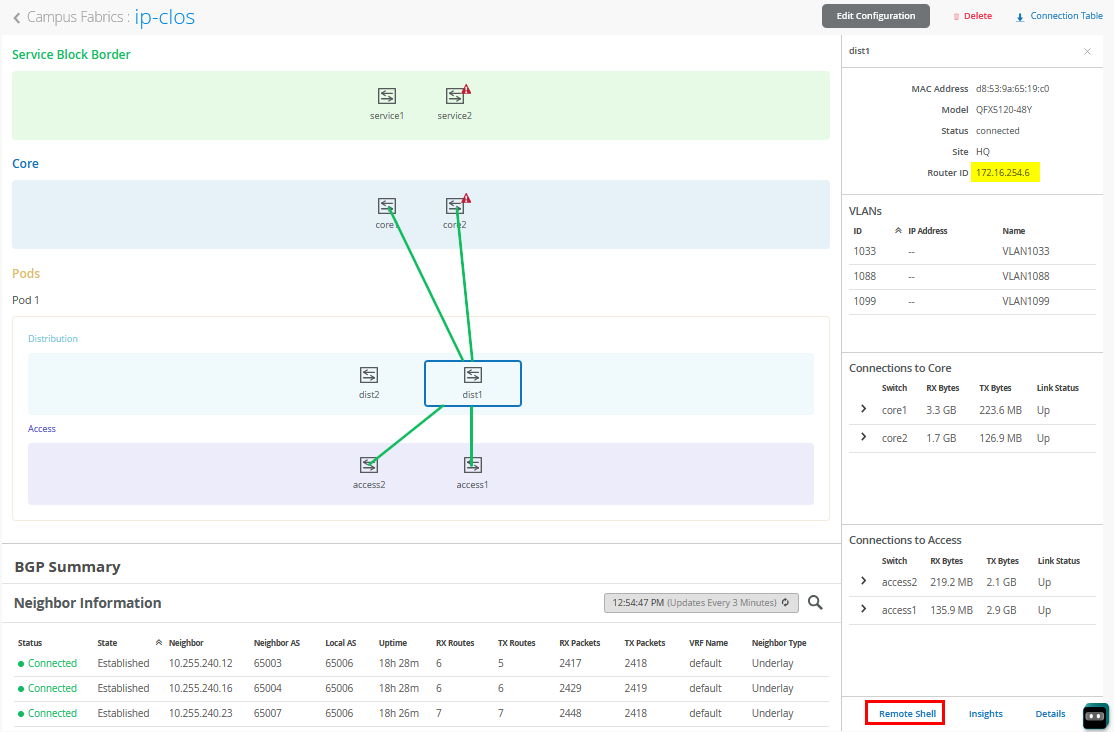
To further validate the campus fabric in the portal, select the Campus Fabric option under the Organization tab on the left side of the portal.
Remote shell access into each device within the campus fabric is supported here as well as a visual representation of the following capabilities:
- Automatically assigned router ID (lo0.0)
- BGP peering establishment.
- Transmit and receive traffic on a link-by-link basis.
- Telemetry, such as LLDP, from each device that verifies the physical build.
BGP Underlay Verification
Purpose
Verifying the state of eBGP between the core and distribution layers is essential for EVPN-VXLAN to operate as expected. This network of point-to-point links between each layer supports:
- Load balancing using ECMP for greater resiliency and bandwidth efficiencies.
- BFD to decrease convergence times during failures.
- Loopback reachability to support VXLAN tunnelling.
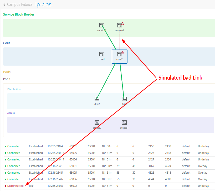
In the above figure, you see a (simulated) bad link between two fabric nodes that you should fix.
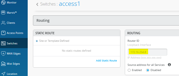
Due to the automated assignment of router IDs and loopback IP addresses in the fabric, we have the following configuration to remember:
| Switch Type | Switch Name | Auto assigned Loopback IP |
|---|---|---|
| Service Block | service1 | 172.16.254.1 |
| Service Block | service2 | 172.16.254.2 |
| Core | core1 | 172.16.254.3 |
| Core | core2 | 172.16.254.4 |
| Distribution | dist1 | 172.16.254.6 |
| Distribution | dist2 | 172.16.254.5 |
| Access Standalone | access1 | 172.16.254.8 |
| Access Virtual Chassis | access2 | 172.16.254.7 |
Another way to find the assigned router ID and loopback IP address is the switch configuration panel as in the below figure:
Action
Verify that BGP sessions are established between core devices and distribution devices to ensure loopback reachability, BFD session status, and load-balancing using ECMP.
Operational data can be gathered through the campus fabric section of the portal as Remote Shell or using an external application such as SecureCRT or Putty.
Verification of BGP Peering
Access the Remote Shell via the lower-right corner of the campus fabric, from the switch view, or via Secure Shell (SSH).
Core1 Switch:
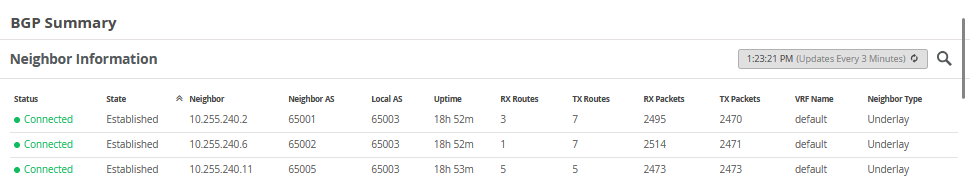
root@core1> show bgp summary
Threading mode: BGP I/O
Default eBGP mode: advertise - accept, receive - accept
Groups: 2 Peers: 8 Down peers: 0
Table Tot Paths Act Paths Suppressed History Damp State Pending
inet.0
14 11 0 0 0 0
bgp.evpn.0
123 54 0 0 0 0
Peer AS InPkt OutPkt OutQ Flaps Last Up/Dwn State|#Active/Received/Accepted/Damped...
10.255.240.2 65001 2496 2471 0 0 18:52:17 Establ
inet.0: 2/3/3/0
10.255.240.6 65002 2515 2472 0 0 18:52:16 Establ
inet.0: 1/1/1/0
10.255.240.11 65005 2474 2474 0 0 18:53:35 Establ
inet.0: 4/5/5/0
10.255.240.13 65006 2476 2472 0 0 18:53:37 Establ
inet.0: 4/5/5/0
172.16.254.1 65001 4250 4380 0 0 18:52:17 Establ
bgp.evpn.0: 1/27/27/0
172.16.254.2 65002 2517 5003 0 0 18:52:14 Establ
bgp.evpn.0: 10/10/10/0
172.16.254.5 65005 4758 4467 0 0 18:53:33 Establ
bgp.evpn.0: 19/43/43/0
172.16.254.6 65006 4723 4469 0 0 18:53:35 Establ
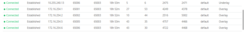
bgp.evpn.0: 24/43/43/0From the BGP summary, we can see that the underlay (10.255.240.X) peer relationships are established, which indicates that the underlay links are attached to the correct devices and the links are up.
It also shows the overlay (172.16.254.x) relationships are established and that it is peering at the correct loopback addresses. This demonstrates underlay loopback reachability.
We can also see routes received; time established are roughly equal which looks good so far.
The campus fabric build illustrates per device real-time BGP peering status shown below from Core1:
If BGP is not established then go back and validate the underlay links and addressing, and that the loopback addresses are correct. Loopback addresses should be pingable from other loopback addresses.
Verification of BGP connections can be performed on any of the other switches (not shown).
The primary goal of eBGP in the underlay is to provide loopback reachability between core and distribution devices in the campus fabric. This loopback is used to terminate VXLAN tunnels between devices. The following shows loopback reachability from Core1 to all devices in the campus fabric:
root@core1> ping 172.16.254.1 count 2
PING 172.16.254.1 (172.16.254.1): 56 data bytes
64 bytes from 172.16.254.1: icmp_seq=0 ttl=64 time=5.385 ms
64 bytes from 172.16.254.1: icmp_seq=1 ttl=64 time=5.962 ms
--- 172.16.254.1 ping statistics ---
2 packets transmitted, 2 packets received, 0% packet loss
round-trip min/avg/max/stddev = 5.385/5.673/5.962/0.289 ms
.
root@core1> ping 172.16.254.2 count 2
PING 172.16.254.2 (172.16.254.2): 56 data bytes
64 bytes from 172.16.254.2: icmp_seq=0 ttl=64 time=1.793 ms
64 bytes from 172.16.254.2: icmp_seq=1 ttl=64 time=7.798 ms
--- 172.16.254.2 ping statistics ---
2 packets transmitted, 2 packets received, 0% packet loss
round-trip min/avg/max/stddev = 1.793/4.795/7.798/3.003 ms
.
root@core1> ping 172.16.254.4 count 2
PING 172.16.254.4 (172.16.254.4): 56 data bytes
64 bytes from 172.16.254.4: icmp_seq=0 ttl=63 time=1.993 ms
64 bytes from 172.16.254.4: icmp_seq=1 ttl=63 time=2.082 ms
--- 172.16.254.4 ping statistics ---
2 packets transmitted, 2 packets received, 0% packet loss
round-trip min/avg/max/stddev = 1.993/2.038/2.082/0.044 ms
.
root@core1> ping 172.16.254.5 count 2
PING 172.16.254.5 (172.16.254.5): 56 data bytes
64 bytes from 172.16.254.5: icmp_seq=0 ttl=64 time=2.224 ms
64 bytes from 172.16.254.5: icmp_seq=1 ttl=64 time=2.883 ms
--- 172.16.254.5 ping statistics ---
2 packets transmitted, 2 packets received, 0% packet loss
round-trip min/avg/max/stddev = 2.224/2.554/2.883/0.329 ms
.
root@core1> ping 172.16.254.6 count 2
PING 172.16.254.6 (172.16.254.6): 56 data bytes
64 bytes from 172.16.254.6: icmp_seq=0 ttl=64 time=5.341 ms
64 bytes from 172.16.254.6: icmp_seq=1 ttl=64 time=3.041 ms
--- 172.16.254.6 ping statistics ---
2 packets transmitted, 2 packets received, 0% packet loss
round-trip min/avg/max/stddev = 3.041/4.191/5.341/1.150 ms
.
root@core1> ping 172.16.254.7 count 2
PING 172.16.254.7 (172.16.254.7): 56 data bytes
64 bytes from 172.16.254.7: icmp_seq=0 ttl=63 time=14.377 ms
64 bytes from 172.16.254.7: icmp_seq=1 ttl=63 time=4.518 ms
--- 172.16.254.7 ping statistics ---
2 packets transmitted, 2 packets received, 0% packet loss
round-trip min/avg/max/stddev = 4.518/9.447/14.377/4.929 ms
.
root@core1> ping 172.16.254.8 count 2
PING 172.16.254.8 (172.16.254.8): 56 data bytes
64 bytes from 172.16.254.8: icmp_seq=0 ttl=63 time=11.385 ms
64 bytes from 172.16.254.8: icmp_seq=1 ttl=63 time=6.309 ms
--- 172.16.254.8 ping statistics ---
2 packets transmitted, 2 packets received, 0% packet loss
round-trip min/avg/max/stddev = 6.309/8.847/11.385/2.538 ms
eBGP sessions are established between core-distribution and core-service layers in the campus fabric. Loopback reachability has also been verified between the core and all other devices.
Let’s verify that the routes are established to the access layer and other devices across multiple paths. For example, Core1 should leverage both paths through dist1 and dist2 to reach access1 and vice versa.
root@core1> show route forwarding-table destination 172.16.254.8
Routing table: default.inet
Internet:
Destination        Type RtRef Next hop           Type Index    NhRef Netif
172.16.254.8/32    user     0                    ulst  2097152     3
                              10.255.240.13      ucst     1725     7 et-0/0/6.0
                              10.255.240.11      ucst     1724     7 et-0/0/7.0
This is the reverse check from access1 to be able to reach core1 via dist1 and dist2 switches.
root@access1> show route forwarding-table destination 172.16.254.3
Routing table: default.inet
Internet:
Destination        Type RtRef Next hop           Type Index    NhRef Netif
172.16.254.3/32    user     0                    ulst   131070    21
                              10.255.240.24      ucst     1775     6 mge-0/0/36.0
                              10.255.240.20      ucst     1774     6 mge-0/0/37.0
Finally, we validate BFD for fast convergence in the case of a link or device failure:
root@core1> show bfd session
.                                                  Detect   Transmit
Address                  State     Interface      Time     Interval  Multiplier
10.255.240.2             Up        et-0/0/8.0     3.000     1.000        3
10.255.240.6             Up        et-0/0/9.0     3.000     1.000        3
10.255.240.11            Up        et-0/0/7.0     3.000     1.000        3
10.255.240.13            Up        et-0/0/6.0     3.000     1.000        3
172.16.254.1             Up                       3.000     1.000        3
172.16.254.2             Up                       3.000     1.000        3
172.16.254.5             Up                       3.000     1.000        3
172.16.254.6             Up                       3.000     1.000        3
.
8 sessions, 8 clients
Cumulative transmit rate 8.0 pps, cumulative receive rate 8.0 pps
Conclusion: At this point, the BGP underlay and overlay are operational through the verification of eBGP between corresponding layers of the campus fabric and loopback routes are established between service, core, distribution and access layers.
We have one link in the fabric that did not come up so we have not met the full requirement before we can go into production. However, we can further use the fabric as all nodes in the fabric can still reach each other.
EVPN VXLAN Verification Between Access and Service Block Switches
Since the desktop can ping its default gateway, we can assume the Ethernet switching tables are correctly populated, and VLAN and interface modes are correct. If pinging the default gateway failed, then troubleshoot client to access connectivity.
In this fabric, the core and distribution switches do not have any VXLAN VTEPs assigned since no VLAN interface is configured there. Hence, we will not find any VXLAN or EVPN information on those devices. Those devices just forward our control and data packets.
Verification of the MAC address table, the EVPN database and remote VXLAN tunnel summary on both access switches is shown below:
Access1 Switch:
root@access1> show ethernet-switching table
MAC flags (S - static MAC, D - dynamic MAC, L - locally learned, P - Persistent static, C - Control MAC
           SE - statistics enabled, NM - non configured MAC, R - remote PE MAC, O - ovsdb MAC,
           B - Blocked MAC)
Ethernet switching table : 7 entries, 7 learned
Routing instance : default-switch
   Vlan                MAC                 MAC       GBP    Logical                SVLBNH/      Active
   name                address             flags     tag    interface              VENH Index   source
   VLAN1033            5c:5b:35:be:84:08   D                mge-0/0/16.0
   VLAN1033            5c:5b:35:be:84:12   DR               vtep.32771                          172.16.254.7
   VLAN1088            52:54:00:32:05:6f   DR               vtep.32771                          172.16.254.7
   VLAN1088            52:54:00:7c:77:40   D                mge-0/0/13.0
   VLAN1099            52:54:00:4a:e5:d0   D                mge-0/0/11.0
   VLAN1099            52:54:00:77:3c:03   DR               vtep.32771                          172.16.254.7
   VLAN1099            52:54:00:7e:f9:b1   D                mge-0/0/14.0
.
root@access1> show evpn database
Instance: default-switch
VLAN  DomainId  MAC address        Active source                  Timestamp        IP address
     10001      f8:c1:16:41:5c:00  irb.0                          Jan 15 17:28:13
     11033      00:00:5e:e4:31:57  irb.1033                       Jan 16 10:51:10  10.33.33.1
     11033      5c:5b:35:be:84:08  mge-0/0/16.0                   Jan 16 10:51:20
     11033      5c:5b:35:be:84:12  172.16.254.7                   Jan 16 10:58:20
     11088      00:00:5e:e4:31:57  irb.1088                       Jan 16 10:51:10  10.88.88.1
     11088      52:54:00:32:05:6f  172.16.254.7                   Jan 16 11:02:28  10.88.88.88
     11088      52:54:00:7c:77:40  mge-0/0/13.0                   Jan 16 13:29:22  10.88.88.23
     11099      00:00:5e:e4:31:57  irb.1099                       Jan 16 10:51:10  10.99.99.1
     11099      3c:fd:fe:d1:65:60  172.16.254.7                   Jan 16 13:35:21
     11099      52:54:00:4a:e5:d0  mge-0/0/11.0                   Jan 16 13:29:22  10.99.99.23
     11099      52:54:00:77:3c:03  172.16.254.7                   Jan 16 11:02:39  10.99.99.42
     11099      52:54:00:7e:f9:b1  mge-0/0/14.0                   Jan 16 13:34:22  10.99.99.99
.
root@access1> show ethernet-switching vxlan-tunnel-end-point remote summary
Logical System Name       Id  SVTEP-IP         IFL   L3-Idx    SVTEP-Mode    ELP-SVTEP-IP
<default>                 0   172.16.254.8     lo0.0    0
 RVTEP-IP         L2-RTT                   IFL-Idx   Interface    NH-Id   RVTEP-Mode  ELP-IP        Flags
 172.16.254.1     default-switch           609       vtep.32769   1776    RNVE
 172.16.254.2     default-switch           610       vtep.32770   1777    RNVE
 172.16.254.7     default-switch           611       vtep.32771   1778    RNVE
Access2 Switch:
root@access2> show ethernet-switching table
MAC flags (S - static MAC, D - dynamic MAC, L - locally learned, P - Persistent static, C - Control MAC
           SE - statistics enabled, NM - non configured MAC, R - remote PE MAC, O - ovsdb MAC,
           B - Blocked MAC)
Ethernet switching table : 9 entries, 9 learned
Routing instance : default-switch
   Vlan                MAC                 MAC       GBP    Logical                SVLBNH/      Active
   name                address             flags     tag    interface              VENH Index   source
   VLAN1033            5c:5b:35:be:84:08   DR               vtep.32771                          172.16.254.8
   VLAN1033            5c:5b:35:be:84:12   D                mge-3/0/16.0
   VLAN1088            3c:fd:fe:d1:65:60   DR               vtep.32771                          172.16.254.8
   VLAN1088            52:54:00:32:05:6f   D                mge-3/0/12.0
   VLAN1088            52:54:00:7c:77:40   DR               vtep.32771                          172.16.254.8
   VLAN1099            3c:fd:fe:d1:65:60   DR               vtep.32771                          172.16.254.8
   VLAN1099            52:54:00:4a:e5:d0   DR               vtep.32771                          172.16.254.8
   VLAN1099            52:54:00:77:3c:03   D                mge-3/0/13.0
   VLAN1099            52:54:00:7e:f9:b1   DR               vtep.32771                          172.16.254.8
.
root@access2> show evpn database
Instance: default-switch
VLAN  DomainId  MAC address        Active source                  Timestamp        IP address
     10001      bc:0f:fe:15:70:80  irb.0                          Jan 15 17:28:15
     11033      00:00:5e:e4:31:57  irb.1033                       Jan 16 10:58:16  10.33.33.1
     11033      5c:5b:35:be:84:08  172.16.254.8                   Jan 16 10:51:20
     11033      5c:5b:35:be:84:12  mge-3/0/16.0                   Jan 16 10:58:20
     11088      00:00:5e:e4:31:57  irb.1088                       Jan 16 10:58:16  10.88.88.1
     11088      52:54:00:32:05:6f  mge-3/0/12.0                   Jan 16 13:39:25  10.88.88.88
     11088      52:54:00:7c:77:40  172.16.254.8                   Jan 16 11:03:59  10.88.88.23
     11099      00:00:5e:e4:31:57  irb.1099                       Jan 16 10:58:16  10.99.99.1
     11099      3c:fd:fe:d1:65:60  mge-3/0/13.0                   Jan 16 13:35:21
     11099      52:54:00:4a:e5:d0  172.16.254.8                   Jan 16 11:03:53  10.99.99.23
     11099      52:54:00:77:3c:03  mge-3/0/13.0                   Jan 16 13:39:25  10.99.99.42
     11099      52:54:00:7e:f9:b1  172.16.254.8                   Jan 16 11:06:20  10.99.99.99
.
root@access2> show ethernet-switching vxlan-tunnel-end-point remote summary
Logical System Name       Id  SVTEP-IP         IFL   L3-Idx    SVTEP-Mode    ELP-SVTEP-IP
<default>                 0   172.16.254.7     lo0.0    0
 RVTEP-IP         L2-RTT                   IFL-Idx   Interface    NH-Id   RVTEP-Mode  ELP-IP        Flags
 172.16.254.1     default-switch           693       vtep.32769   1870    RNVE
 172.16.254.2     default-switch           694       vtep.32770   1871    RNVE
 172.16.254.8     default-switch           695       vtep.32771   1877    RNVE
Both access switches have all three VLANs assigned locally hence they will show information about local MAC-Addresses as well as once learned remotely via EVPN. The EVPN Database also reflects this learning. Also, the individual remote VXLAN VTEP’s are learned using the router ID / lo0.0 assigned to remote switches.
Verification of the MAC-Address table, the EVPN Database and remote VXLAN-Tunnel summary on both Service Block Switches.
Service1 Switch:
root@service1> show ethernet-switching table
.
root@service1> show evpn database
Instance: default-switch
VLAN  DomainId  MAC address        Active source                  Timestamp        IP address
     10001      74:e7:98:06:d1:00  irb.0                          Jan 15 17:27:58
     11033      5c:5b:35:be:84:08  172.16.254.8                   Jan 16 10:51:20
     11033      5c:5b:35:be:84:12  172.16.254.7                   Jan 16 10:58:20
     11088      52:54:00:32:05:6f  172.16.254.7                   Jan 16 11:02:28  10.88.88.88
     11088      52:54:00:7c:77:40  172.16.254.8                   Jan 16 11:03:59  10.88.88.23
     11099      3c:fd:fe:d1:65:60  172.16.254.8                   Jan 16 14:06:14
     11099      52:54:00:4a:e5:d0  172.16.254.8                   Jan 16 11:03:53  10.99.99.23
     11099      52:54:00:77:3c:03  172.16.254.7                   Jan 16 11:02:39  10.99.99.42
     11099      52:54:00:7e:f9:b1  172.16.254.8                   Jan 16 11:06:20  10.99.99.99
.
root@service1> show ethernet-switching vxlan-tunnel-end-point remote summary
Logical System Name       Id  SVTEP-IP         IFL   L3-Idx    SVTEP-Mode    ELP-SVTEP-IP
<default>                 0   172.16.254.1     lo0.0    0
 RVTEP-IP         L2-RTT                   IFL-Idx   Interface    NH-Id   RVTEP-Mode  ELP-IP        Flags
 172.16.254.2     default-switch           822       vtep.32769   1750    RNVE
 172.16.254.7     default-switch           823       vtep.32770   1753    RNVE
 172.16.254.8     default-switch           824       vtep.32771   1754    RNVE
Service2 Switch:
root@service2> show ethernet-switching table
.
root@service2> show evpn database
Instance: default-switch
VLAN  DomainId  MAC address        Active source                  Timestamp        IP address
     10001      74:e7:98:0f:a0:00  irb.0                          Jan 15 17:27:58
     11033      5c:5b:35:be:84:08  172.16.254.8                   Jan 16 10:51:20
     11033      5c:5b:35:be:84:12  172.16.254.7                   Jan 16 10:58:20
     11088      52:54:00:32:05:6f  172.16.254.7                   Jan 16 11:02:28  10.88.88.88
     11088      52:54:00:7c:77:40  172.16.254.8                   Jan 16 11:03:59  10.88.88.23
     11099      3c:fd:fe:d1:65:60  172.16.254.8                   Jan 16 14:06:14
     11099      52:54:00:4a:e5:d0  172.16.254.8                   Jan 16 11:03:53  10.99.99.23
     11099      52:54:00:77:3c:03  172.16.254.7                   Jan 16 11:02:39  10.99.99.42
     11099      52:54:00:7e:f9:b1  172.16.254.8                   Jan 16 11:06:20  10.99.99.99
     11099      ac:1f:6b:02:af:59  172.16.254.8                   Jan 16 14:10:15
.
root@service2> show ethernet-switching vxlan-tunnel-end-point remote summary
Logical System Name       Id  SVTEP-IP         IFL   L3-Idx    SVTEP-Mode    ELP-SVTEP-IP
<default>                 0   172.16.254.2     lo0.0    0
 RVTEP-IP         L2-RTT                   IFL-Idx   Interface    NH-Id   RVTEP-Mode  ELP-IP        Flags
 172.16.254.1     default-switch           848       vtep.32769   1834    RNVE
 172.16.254.7     default-switch           849       vtep.32770   1839    RNVE
 172.16.254.8     default-switch           850       vtep.32771   1840    RNVE
At this point, you won’t see any data in the Ethernet switching table on the service block switches, since no VLAN is defined there yet. The EVPN database is in sync between the service block switches, which is expected. Also, the individual remote VXLAN VTEPs are learned using the router ID / lo0.0 assigned to the remote switches.
In the next step, we verify the configuration of
VLAN1099 and what VNI was assigned to it on the two
access and service block switches:
root@access1> show configuration vlans | display set | display inheritance | match 1099
set vlans VLAN1099 vlan-id 1099
set vlans VLAN1099 l3-interface irb.1099
set vlans VLAN1099 vxlan vni 11099
.
root@access2> show configuration vlans | display set | display inheritance | match 1099
set vlans VLAN1099 vlan-id 1099
set vlans VLAN1099 l3-interface irb.1099
set vlans VLAN1099 vxlan vni 11099
.
root@service1> show configuration vlans | display set | display inheritance | match 1099
.
root@service1>
.
root@service2> show configuration vlans | display set | display inheritance | match 1099
.
root@service2>
Juniper Mist cloud management does not enable a user to configure the value for the VNI used for a particular VLAN so as to maintain consistency among different fabrics. Today the VNI is calculated by the VLAN-ID + 10.000 (but may change in the future).
We need to configure the attachment of the WAN router to complete the entire design. Without the WAN router configuration, the fabric only enables the following communications:
- The same VLAN/VNI on the same access switch but different ports.
- The same VLAN/VNI on different access switches.
- Different VLAN/VNI attached to the same VRF on the same access switch, but different ports.
- Different VLAN/VNI attached to the same VRF on different access switches.
All traffic between VRFs is always isolated inside the fabric. For security reasons, there is no possible configuration to perform route leaking between VRFs. This means that traffic between them is handled directly inside the fabric without the need to traverse through the WAN router as a possible enforcement point.