APPENDIX: Example IP Clos Fabric Creation
In this chapter, we demonstrate the creation of an IP Clos fabric managed by Juniper Mist cloud. This is a small lab with physical devices as a single site fabric to begin with.
It is possible to build a virtual campus fabric to explore the major functionality without Virtual Chassis and VXLAN-GBP testing capabilities. If you are interested, please review the following Network Configuration Example.
Campus Fabric IP Clos Lab Components
This configuration example uses the following devices:
- Two Juniper Networks® QFX10002 Switches as core devices.
- Two Juniper Networks® QFX5120 Switches as distribution devices.
- One Juniper Networks® EX4400-MP Switch as a standalone access device.
- Four EX4400-MP Switches as Virtual Chassis access devices.
- Two Juniper Networks® QFX5120 Switches as service block devices.
- One Juniper Networks® SRX1500 as a WAN router. Integration to fabric utilizes eBGP.
- A Linux-based DHCP server for the fabric. Externally attached to the fabric.
- Juniper® Series of High-Performance Access Points.
- Various Linux desktops that act as wired/wireless clients.
The following Lab-topology was used:
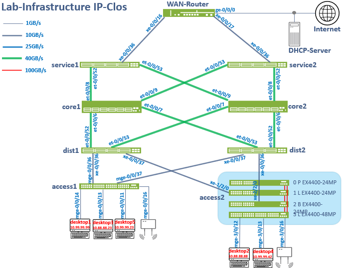
This picture does not show the required out-of-band management network that each core, distribution, service block and access switch requires to be managed by the Juniper Mist cloud (and for functions like RADIUS authentication). You need to design for that as well.
Juniper Mist Wired Assurance
Juniper Mist Wired Assurance, through the Juniper Mist portal, can be used to centrally manage all Juniper switches. Juniper Mist Wired Assurance gives you full visibility into the devices that comprise your network’s access layer. The portal provides a user interface to access your architecture through the AI-driven cloud services with your Juniper Mist account. You can monitor, measure, and get alerts on key compliance metrics on the wired network. This includes switch version and PoE compliance, switch-AP affinity, and VLAN insights.
Juniper switch onboarding to the Juniper Mist cloud: https://www.juniper.net/documentation/us/en/quick-start/hardware/cloud-ready-switches/topics/topic-map/step-1-begin.html
Juniper Mist Wired Assurance, through the portal, is used to build a campus fabric IP Clos from the ground up. This includes the following:
- Assignment of point-to-point (P2P) links between the core, distribution, service block and access layers.
- Assignment of unique BGP AS numbers per device participating in the underlay and overlay.
- The creation of VRF instances allows you to logically segment traffic. This also includes the assignment of new or existing VLANs to each representative VRF.
- IP addressing of each L3 gateway integrated routing and bridging (IRB) interface assigned to the access layer.
- IP addressing of each loopback interface.
- Configuration of routing policies for underlay and overlay connectivity.
- Optimized maximum transmission unit (MTU) settings for P2P underlay, L3 IRB, and ESI-LAG bundles.
- Downloadable connection table (CSV format) that can be used by those involved in the physical buildout of the campus fabric.
- Graphical interface depicting all devices with BGP peering and physical link status.
For more information on Juniper Mist Wired Assurance, see: https://www.mist.com/documentation/category/wired-assurance/
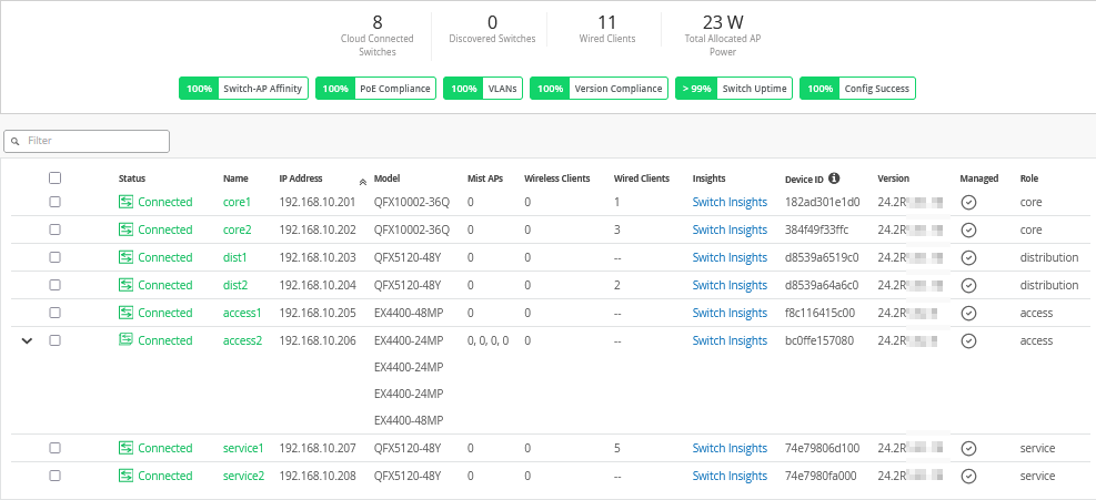
Juniper Mist Wired Assurance Switches
You must validate that each device participating in the campus fabric has been adopted or claimed and assigned to a site. The switches are named for their respective layers in the fabric to facilitate building and operating the fabric.
Templates
A key feature of switch management through the Juniper Mist cloud is to use templates and a hierarchical model to group the switches and make bulk updates. Templates provide uniformity and convenience, while the hierarchy (site and switch) provides both scale and granularity.
Templates and the hierarchical model means that you can create a template configuration and then all the devices in each group inherit the template settings. When a conflict occurs, for example, when there are settings at both the site and organizational levels that apply to the same device, the narrower settings (in this case, the site settings) override the broader settings defined at the organization level.
Individual switches, at the bottom of the hierarchy, can inherit all or part of the configuration defined at the organization level, and again at the site level. Of course, individual switches can also have their own unique configurations.
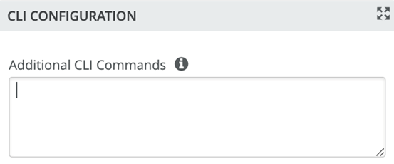
You can include individual CLI commands at any level of the hierarchy, which are then appended to all the switches in that group on an “AND” basis—that is, individual CLI settings are appended to the existing configuration (existing settings might be replaced or appended).
If you run CLI commands for items not native to the portal, this configuration data is applied last; overwriting existing configuration data within the same stanza. You can access the CLI command option from the switch template or individual switch configuration.
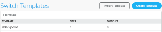
Under organization and switch templates, we use the following template:
We provide a copy of the following template in JSON format for importing into your own system for verification:
{
  "additional_config_cmds": [],
  "networks": {
    "VLAN1033": {
      "vlan_id": "1033",
      "subnet": "10.33.33.0/24",
      "subnet6": ""
    },
    "VLAN1088": {
      "vlan_id": "1088",
      "subnet": "10.88.88.0/24",
      "subnet6": ""
    },
    "VLAN1099": {
      "vlan_id": "1099",
      "subnet": "10.99.99.0/24",
      "subnet6": ""
    }
  },
  "port_usages": {
    "vlan1099-no-auth": {
      "mode": "access",
      "disabled": false,
      "port_network": "VLAN1099",
      "voip_network": null,
      "stp_edge": false,
      "port_auth": null,
      "allow_multiple_supplicants": null,
      "enable_mac_auth": null,
      "mac_auth_only": null,
      "guest_network": null,
      "bypass_auth_when_server_down": null,
      "dynamic_vlan_networks": null,
      "stp_p2p": false,
      "stp_no_root_port": false,
      "mac_auth_protocol": null,
      "reauth_interval": null,
      "all_networks": false,
      "networks": null,
      "speed": "auto",
      "duplex": "auto",
      "mac_limit": 0,
      "persist_mac": false,
      "poe_disabled": false,
      "enable_qos": false,
      "storm_control": {},
      "mtu": null,
      "description": "",
      "disable_autoneg": false
    },
    "vlan1088-no-auth": {
      "disabled": false,
      "mode": "access",
      "port_network": "VLAN1088",
      "voip_network": null,
      "stp_edge": false,
      "port_auth": null,
      "allow_multiple_supplicants": null,
      "enable_mac_auth": null,
      "mac_auth_only": null,
      "guest_network": null,
      "bypass_auth_when_server_down": null,
      "dynamic_vlan_networks": null,
      "stp_p2p": false,
      "stp_no_root_port": false,
      "mac_auth_protocol": null,
      "reauth_interval": null,
      "all_networks": false,
      "networks": null,
      "speed": "auto",
      "duplex": "auto",
      "mac_limit": 0,
      "persist_mac": false,
      "poe_disabled": false,
      "enable_qos": false,
      "storm_control": {},
      "mtu": null,
      "description": "",
      "disable_autoneg": false
    },
    "vlan1099-eap-auth": {
      "mode": "access",
      "disabled": false,
      "port_network": "VLAN1099",
      "voip_network": null,
      "stp_edge": false,
      "port_auth": "dot1x",
      "allow_multiple_supplicants": false,
      "enable_mac_auth": false,
      "mac_auth_only": false,
      "guest_network": null,
      "bypass_auth_when_server_down": false,
      "dynamic_vlan_networks": null,
      "stp_p2p": false,
      "stp_no_root_port": false,
      "mac_auth_protocol": null,
      "reauth_interval": "65000",
      "all_networks": false,
      "networks": null,
      "speed": "auto",
      "duplex": "auto",
      "mac_limit": 0,
      "persist_mac": false,
      "poe_disabled": false,
      "enable_qos": false,
      "storm_control": {},
      "mtu": null,
      "description": "",
      "disable_autoneg": false
    },
    "dynamic": {
      "mode": "dynamic",
      "rules": []
    },
    "vlan1088-eap-auth": {
      "disabled": false,
      "mode": "access",
      "port_network": "VLAN1088",
      "voip_network": null,
      "stp_edge": false,
      "port_auth": "dot1x",
      "allow_multiple_supplicants": false,
      "enable_mac_auth": false,
      "mac_auth_only": false,
      "guest_network": null,
      "bypass_auth_when_server_down": false,
      "dynamic_vlan_networks": null,
      "stp_p2p": false,
      "stp_no_root_port": false,
      "mac_auth_protocol": null,
      "reauth_interval": "65000",
      "all_networks": false,
      "networks": null,
      "speed": "auto",
      "duplex": "auto",
      "mac_limit": 0,
      "persist_mac": false,
      "poe_disabled": false,
      "enable_qos": false,
      "storm_control": {},
      "mtu": null,
      "description": "",
      "disable_autoneg": false
    },
    "access-point": {
      "mode": "trunk",
      "disabled": false,
      "port_network": "VLAN1033",
      "voip_network": null,
      "stp_edge": false,
      "port_auth": null,
      "allow_multiple_supplicants": null,
      "enable_mac_auth": null,
      "mac_auth_only": null,
      "guest_network": null,
      "bypass_auth_when_server_down": null,
      "dynamic_vlan_networks": null,
      "stp_p2p": false,
      "stp_no_root_port": false,
      "mac_auth_protocol": null,
      "reauth_interval": null,
      "all_networks": true,
      "networks": [],
      "speed": "auto",
      "duplex": "auto",
      "mac_limit": 0,
      "persist_mac": false,
      "poe_disabled": false,
      "enable_qos": false,
      "storm_control": {},
      "mtu": null,
      "description": "",
      "disable_autoneg": false
    },
    "vlan1099-mab-auth": {
      "mode": "access",
      "disabled": false,
      "port_network": "VLAN1099",
      "voip_network": null,
      "stp_edge": false,
      "port_auth": "dot1x",
      "allow_multiple_supplicants": true,
      "enable_mac_auth": true,
      "mac_auth_only": true,
      "guest_network": null,
      "bypass_auth_when_server_down": false,
      "dynamic_vlan_networks": null,
      "stp_p2p": false,
      "stp_no_root_port": false,
      "mac_auth_protocol": "pap",
      "reauth_interval": "65000",
      "all_networks": false,
      "networks": null,
      "speed": "auto",
      "duplex": "auto",
      "mac_limit": 0,
      "persist_mac": false,
      "poe_disabled": false,
      "enable_qos": false,
      "storm_control": {},
      "mtu": null,
      "description": "",
      "disable_autoneg": false
    },
    "vlan1088-mab-auth": {
      "disabled": false,
      "mode": "access",
      "port_network": "VLAN1088",
      "voip_network": null,
      "stp_edge": false,
      "port_auth": "dot1x",
      "allow_multiple_supplicants": true,
      "enable_mac_auth": true,
      "mac_auth_only": true,
      "guest_network": null,
      "bypass_auth_when_server_down": false,
      "dynamic_vlan_networks": null,
      "stp_p2p": false,
      "stp_no_root_port": false,
      "mac_auth_protocol": "pap",
      "reauth_interval": "65000",
      "all_networks": false,
      "networks": null,
      "speed": "auto",
      "duplex": "auto",
      "mac_limit": 0,
      "persist_mac": false,
      "poe_disabled": false,
      "enable_qos": false,
      "storm_control": {},
      "mtu": null,
      "description": "",
      "disable_autoneg": false
    }
  },
  "disabled_system_defined_port_usages": [],
  "extra_routes": {},
  "extra_routes6": {},
  "switch_mgmt": {
    "config_revert_timer": 10,
    "root_password": "",
    "local_accounts": {},
    "protect_re": {
      "enabled": false
    },
    "tacacs": {
      "enabled": false
    }
  },
  "mist_nac": {
    "enabled": true,
    "network": null
  },
  "radius_config": {
    "auth_servers": [],
    "acct_servers": [],
    "auth_servers_timeout": 5,
    "auth_servers_retries": 3,
    "fast_dot1x_timers": false,
    "acct_interim_interval": 0,
    "auth_server_selection": "ordered",
    "coa_enabled": false,
    "coa_port": ""
  },
  "vrf_config": {
    "enabled": false
  },
  "remote_syslog": {
    "enabled": false
  },
  "snmp_config": {
    "enabled": false
  },
  "dhcp_snooping": {
    "enabled": false
  },
  "bgp_config": null,
  "routing_policies": {},
  "dns_servers": [
    "8.8.8.8",
    "9.9.9.9"
  ],
  "dns_suffix": [],
  "ntp_servers": [
    "192.168.10.1"
  ],
  "acl_policies": [],
  "port_mirroring": {},
  "switch_matching": {
    "enable": true,
    "rules": []
  },
  "name": "dc82-ip-clos"
}
Topology
Juniper Mist Wired Assurance provides the configuration for LAN and loopback IP addressing for each core, distribution, service block and access device once the device’s management IP address is reachable. Each device is provisioned with a /32 loopback address and /31 point-to-point interfaces that interconnect the switch devices within the campus fabric IP-Clos down to the access layer as well in opposite to other designs.
The WAN router can be provisioned through the portal but is separate from the campus fabric workflow. The WAN router has an eBGP peering enabled and exchanges routes with the service block switches of the fabric. WAN routers can be standalone or built as a high availability cluster. In this document, a single SRX Firewall is used as the WAN router.
There is a JVD extension available covering more details on WAN router integration especially for production grade installations. What is shown here does not have the required redundancy for production as it is just a single WAN router.
Create the Campus Fabric
- From Organization on the left-hand side of the
portal, select Campus Fabric.
Figure 5: Campus Fabric Creation
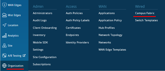
Juniper Mist provides the option of deploying a campus fabric at the organizational or site level noted in the upper-left corner of the campus fabric menu shown below. Both designs now allow you to build fabrics with just a single PoD or multiple PoDs based on customer requirements to connect multiple buildings.
In our example here, the fabric was built on the site level with a single PoD only.
Figure 6: Fabric Site Level Creation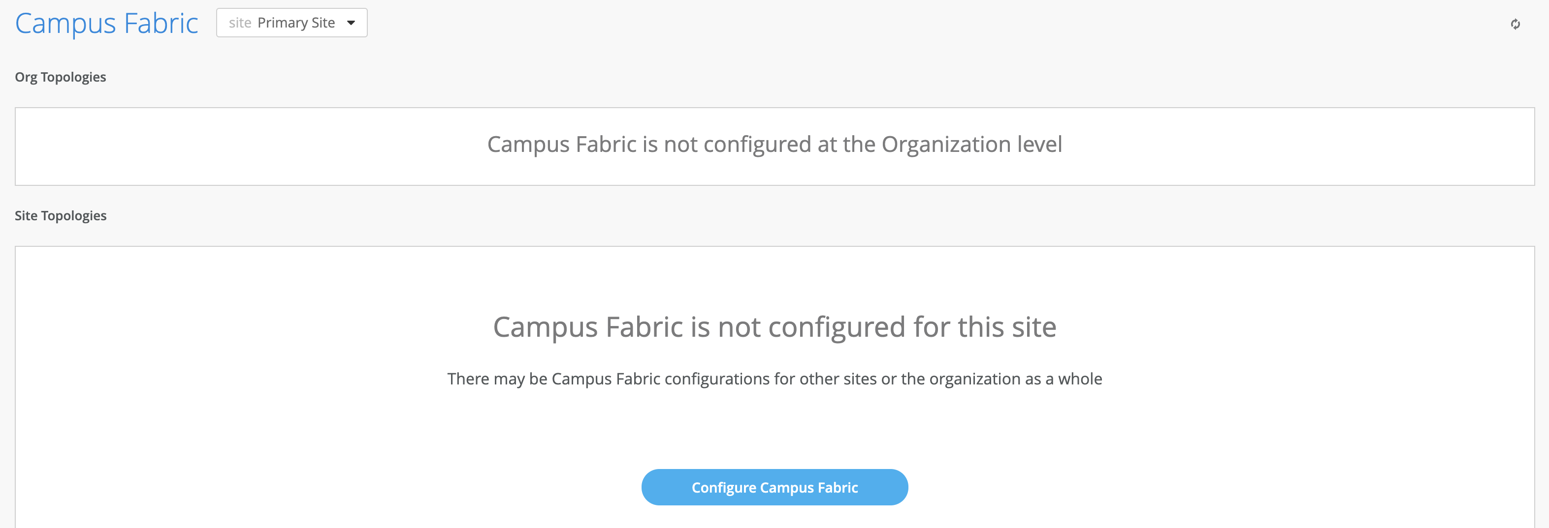
Choose the Campus Fabric Topology
- Select the Campus Fabric IP Clos option below
and configure the following:
- Topology Type=
Campus Fabric IP Clos - Topology Name=
ip-clos - BGP Local AS=
65001(this is the default setting) - Underlay=
IPv4(this is the default setting) - Subnet=
10.255.240.0/20(this is the default setting) - Auto Route ID Subnet / Loopback
Interface=
172.16.254.0/23(this is the default setting) - Loopback per VRF subnet=
172.16.192.0/24(this is the default setting)Figure 7: IP Clos Fabric Creation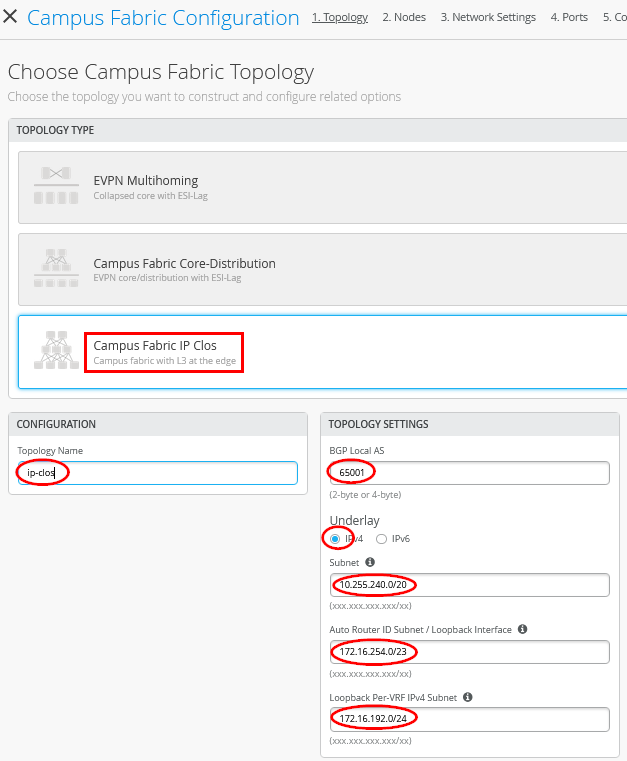
Topology Settings
- BGP Local AS—Represents the starting point of private BGP AS numbers that are automatically allocated per device. You can use whatever private BGP AS number range suits your deployment.
- Subnet—Represents the pool of IP addresses used for point-to-point links between devices. You can use whatever range suits your deployment. Juniper Mist breaks this subnet into /31 subnet addressing per link. This number can be modified to suit the specific deployment scale. For example, /24 provides up to 128 P2P /31 subnets.
- Auto Router ID Subnet—Represents the pool of IP addresses associated with each device’s loopback address. Each device will automatically get a loopback IP address of /32 assigned from this pool. You can use whatever range suits your deployment. VXLAN tunnelling using a VTEP is associated with this address. The loopback IP addresses assigned here are only visible in the underlay transport network. The definition of these underlay loopback IP addresses is critical for the operation of the EVPN-VXLAN fabric to function at all.
- Loopback per-VRF-subnet—Represents a second pool of loopback IP addresses which are each associated with an L3 VRF and switch of the overlay fabric network. It is designed for scale-out services in the overlay network where some services, like DHCP relay, share a single IP address external to the fabric. This is the case for anycast fabrics like ERB and IP Clos. If those L3 VRFs use a dedicated loopback IP address per VRF and switch, it is easy to send return answers to an originating VRF/switch.
Note:We recommend default settings for all options unless they conflict with other networks attached to the campus fabric. The P2P links between each layer utilize /31 addressing to conserve addresses.
Select Campus Fabric Nodes
- Topology Type=
- Select devices to participate in each layer of the campus
fabric IP Clos. We recommend that you validate each device’s
presence in the site switch inventory prior to the creation of the
campus fabric.
The next step is to assign the switches to the layers. Since the switches were named relative to target layer functionality, they can be quickly assigned to their roles.
The service block router is where the campus fabric interconnects external devices such as firewalls, routers, or critical devices. For example, DHCP and RADIUS servers. Devices to which external services connect to the campus fabric are known as border leafs. If you want to connect these services or devices to the campus fabric.
IP Clos in a separate device or pair of devices, clear the Use Core as border option and select the Select Switches option to choose the devices as this is the case for our topology.
Figure 8: Service Block Switch Configuration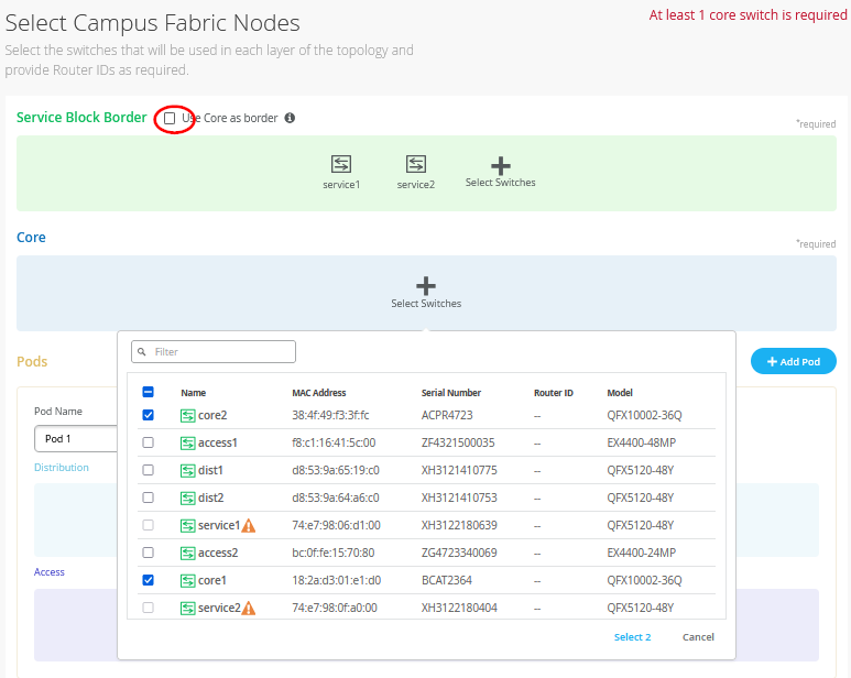 Note:
Note:Placing the service block router on a dedicated pair of switches (or single switch) alleviates the encapsulation and de-capsulation of VXLAN headers from the core layer. If you want to combine this capability within the core devices, you must select the Use Core as border option.
The final configuration of all nodes of the fabric at their topology should look like the figure below.
Figure 9: Fabric Configuration of All Nodes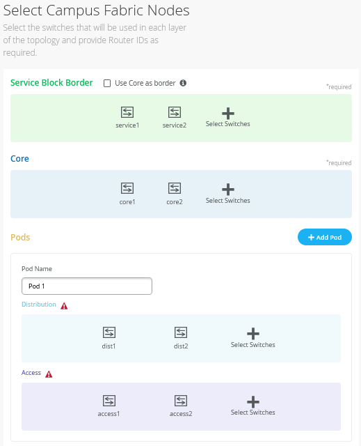
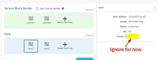
- Once all layers have selected the appropriate devices, you must
provide an underlay loopback IP address for each device. This
loopback interface is associated with a logical construct called a
VTEP; used to source the VXLAN tunnel. The campus fabric IP Clos
has VTEPs for VXLAN tunnelling on all nodes of the fabric. When
defining an auto router ID subnet prefix, the underlay loopback IP
address and router ID assignments happen automatically. There is no
way to manually assign them as it was possible in older versions of
previous documentation.
Figure 10: Fabric Node has No Initial Router ID Assigned Yet.
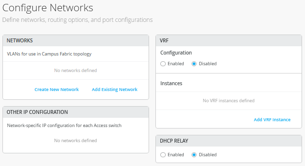
Configuring Networks
- Enter the network information such as VLANs and VRF options.
VLANs are mapped to VNIs and can optionally be mapped to VRFs to
provide a way to logically separate traffic such as device traffic
from corporate traffic.
Figure 11: Configure Networks
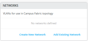
Networks
- VLANs can be created or imported under this section including
the IP subnet and default gateway per each VLAN. The Shared
Elements section of the campus fabric template includes the
networks section mentioned above where VLANs are created.
Figure 12: Default Known Networks
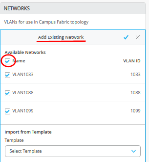
- Back to the campus fabric build, select Add Existing
Network using the existing template which includes L2 VLAN
information. All VLAN and IP information is inherited from the
template.
Figure 13: Network Import from Template
Networks can be edited, newly added or added from an existing template:
Figure 14: Edit a Network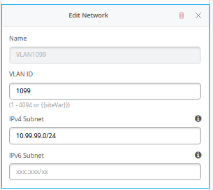
Other IP Configuration
Juniper Mist Wired Assurance provides automatic IP addressing for IRB interfaces for each of the VLANs. Port profiles and port configurations then associate the VLAN with specified ports. In this case, we selected campus fabric IP Clos at the onset of the campus fabric build. This fabric type uses anycast addressing for all devices participating in the L3 subnet. In this case, all access switches are configured with the same IP address for each L3 subnet.
More information on anycast gateways can be found here: https://www.juniper.net/documentation/us/en/software/junos/evpn-vxlan/topics/concept/evpn-mclag-irb-gateway-anycast-address.html
Figure 15: Anycast GW on Access Switch 1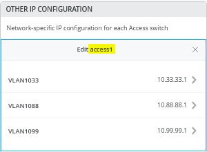 Figure 16: Anycast GW on Access2 VC Switch
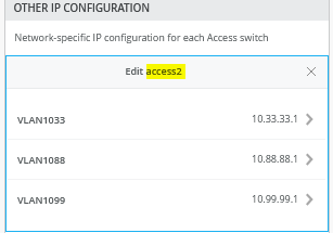
By default, all VLANs are placed in the default VRF. The VRF option allows you to group common VLANs into the same VRF or separate VRFs depending on traffic isolation requirements. This example includes three VRFs or routing instances: corp-it, developers, and guest-wifi.
Note:In our example, we use a VLAN per VRF as that is the minimum requirement. You can always add multiple VLANs to a particular VRF but by default the traffic between these VLANs is always allowed and not controlled by firewalls. The IP Clos fabric type when using EX4100 or EX4400 Switches as access switches does allow more granular control of the traffic inside and between VLANs at the same VRF by using VXLAN-GBP. In this case, it’s better to design for a single, global VRF of the fabric where all VLANs are located.
- Here, you build the first corp-it VRF and select the
pre-defined vlan 1099.
Figure 17: Enable VRF
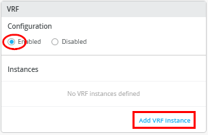 Figure 18: Assign First Network to VRF1
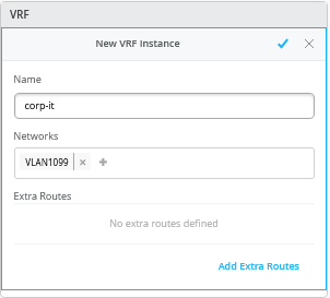
- Create two additional VRFs:
- VRF2=
developerswith Network=VLAN1088 - VRF3=
guest-wifiwith Network=VLAN1033Figure 19: 3 VRFs with At Least One Network Each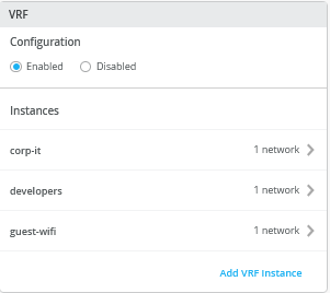
- VRF2=
- Assign to each VLAN our external DHCP server using DHCP
relay.Note:
Information about DHCP relay usage and proper design with campus fabrics is available via the following JVD extension.
Figure 20: Enable DHCP Relay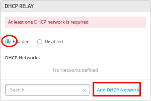
Assign as DHCP relay:
- Network=
VLAN1099 - IPv4 DHCP Servers=
192.168.10.11(In a production network, use two servers as recommended)
Figure 21: DHCP Relay for First Network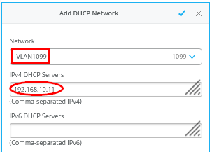
Assign the two remaining networks to the same DHCP server=
192.168.10.11Figure 22: DHCP Relay for All Networks Configured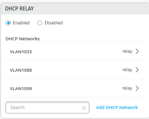
Configure Campus Fabric Ports
- Network=
- The final step is the selection of physical ports among
service, core, distribution and access switches.
Figure 23: Port Overview
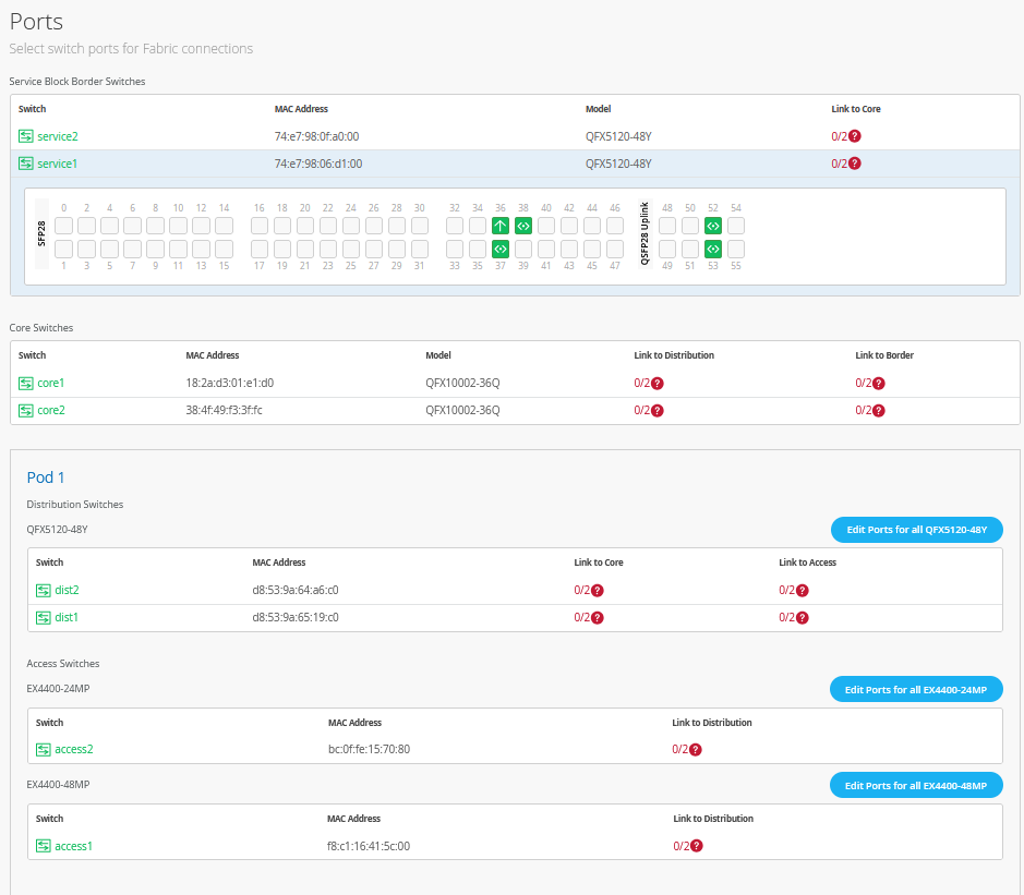
In the current state shown here, all fabric switches are deployed and have OOBM connections to the Juniper Mist cloud to get managed. The fabric links among the switches are also wired already. As all switches send and receive LLDP neighbor messages, we can make use of this fact during the up and downlink configuration of each switch selecting the right interfaces. Here is how this process works using the example of service1 switch.
The links where nothing is attached to each other have no color, hence we just have to click in the remaining ports that are green one by one and review the interface name and reported link member. In the example below the interface reported is
xe-0/0/36and the LLDP neighbor’s name iswanrouter.Figure 24: service1 switch port 36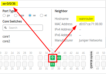
When you go further, you click port 52 where the LLDP neighbor name
core1also appears in the list of configurable switches. It is obvious that you only need to selectcore1from the list as it’s already reported as an LLDP neighbor.Figure 25: service1 switch port 52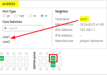
When you check the port after configuration, you should have 1:1 mapping between the configured switch name and the reported LLDP neighbor.
Figure 26: Check Port Config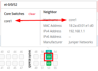
With other fabric switches you may need to additionally configure whether the neighbor is an uplink or downlink neighbor. In the example below, we are on port 6 of core1 switch. The LLDP neighbor name
dist1tells us that this is a downlink neighbor from core to distribution. Hence, we click on Link to Distribution.Figure 27: core1 switch port 6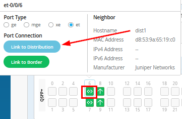
When we selected the right Port Configuration, we should see the reported LLDP neighbor appearing in the list of selectable switches to be synced.
Figure 28: Sync the Reported LLDP Neighbor to Configured Switch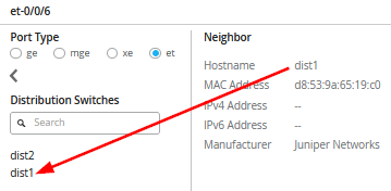
The above approach helps you make the right configuration choices based on the displayed LLDP neighbors and quickly finish the port configuration in a consistent manner. Also always look that you see the expected port type automatically appearing. If that is not the case, you may have wrong optics or missed some additional Junos CLI to convert a port from the default type to another one.
The other way to configure is based on the desired topology and then confirm the links coming up after fabric creation.
The entire configuration for this fabric is as follows:
- Node=
service1- Port #=
1- Used as=
Downlink - Interface=
et-0/0/52 - Switch type=
Core Switches - Switch Name Configured=
core1
- Used as=
- Port #=
2- Used as=
Downlink - Interface=
et-0/0/53 - Switch type=
Core Switches - Switch Name Configured=
core2
- Used as=
- Port #=
- Node=
service2- Port #=
1- Used as=
Downlink - Interface=
et-0/0/52 - Switch type=
Core Switches - Switch Name Configured=
core2
- Used as=
- Port #=
2- Used as=
Downlink - Interface=
et-0/0/53 - Switch type=
Core Switches - Switch Name Configured=
core1
- Used as=
- Port #=
- Node=
core1- Port #=
1- Used as=
Downlink - Interface=
et-0/0/6 - Switch type=
Distribution Switches - Switch Name Configured=
dist1
- Used as=
- Port #=
2- Used as=
Downlink - Interface=
et-0/0/7 - Switch type=
Distribution Switches - Switch Name Configured=
dist2
- Used as=
- Port #=
3- Used as=
Uplink - Interface=
et-0/0/8 - Switch type=
Border Switches - Switch Name Configured=
service1
- Used as=
- Port #=
4- Used as=
Uplink - Interface=
et-0/0/9 - Switch type=
Border Switches - Switch Name Configured=
service2
- Used as=
- Port #=
- Node=
core2- Port #=
1- Used as=
Downlink - Interface=
et-0/0/6 - Switch type=
Distribution Switches - Switch Name Configured=
dist2
- Used as=
- Port #=
2- Used as=
Downlink - Interface=
et-0/0/7 - Switch type=
Distribution Switches - Switch Name Configured=
dist1
- Used as=
- Port #=
3- Used as=
Uplink - Interface=
et-0/0/8 - Switch type=
Border Switches - Switch Name Configured=
service2
- Used as=
- Port #=
4- Used as=
Uplink - Interface=
et-0/0/9 - Switch type=
Border Switches - Switch Name Configured=
service1
- Used as=
- Port #=
- Node=
dist1- Port #=
1- Used as=
Downlink - Interface=
xe-0/0/36 - Switch type=
Access Switches - Switch Name Configured=
access1
- Used as=
- Port #=
2- Used as=
Downlink - Interface=
xe-0/0/37 - Switch type=
Access Switches - Switch Name Configured=
access2
- Used as=
- Port #=
3- Used as=
Uplink - Interface=
et-0/0/52 - Switch type=
Core Switches - Switch Name Configured=
core1
- Used as=
- Port #=
4- Used as=
Uplink - Interface=
et-0/0/53 - Switch type=
Core Switches - Switch Name Configured=
core2
- Used as=
- Port #=
- Node=
dist2- Port #=
1- Used as=
Downlink - Interface=
xe-0/0/36 - Switch type=
Access Switches - Switch Name Configured=
access2
- Used as=
- Port #=
2- Used as=
Downlink - Interface=
xe-0/0/37 - Switch type=
Access Switches - Switch Name Configured=
access1
- Used as=
- Port #=
3- Used as=
Uplink - Interface=
et-0/0/52 - Switch type=
Core Switches - Switch Name Configured=
core2
- Used as=
- Port #=
4- Used as=
Uplink - Interface=
et-0/0/53 - Switch type=
Core Switches - Switch Name Configured=
core1
- Used as=
- Port #=
- Node=
access1- Port #=
1- Used as=
Uplink - Interface=
mge-0/0/36 - Switch type=
Distribution Switches - Switch Name Configured=
dist1
- Used as=
- Port #=
2- Used as=
Uplink - Interface=
mge-0/0/37 - Switch type=
Distribution Switches - Switch Name Configured=
dist2
- Used as=
- Port #=
- Node=
access2- Port #=
1- Used as=
Uplink - Interface=
xe-1/2/0 - Switch type=
Distribution Switches - Switch Name Configured=
dist1
- Used as=
- Port #=
2- Used as=
Uplink - Interface=
xe-2/2/0 - Switch type=
Distribution Switches - Switch Name Configured=
dist2
- Used as=
- Port #=
After you configure all requested links, you should see something similar.
Figure 29: Completed Final Port Configuration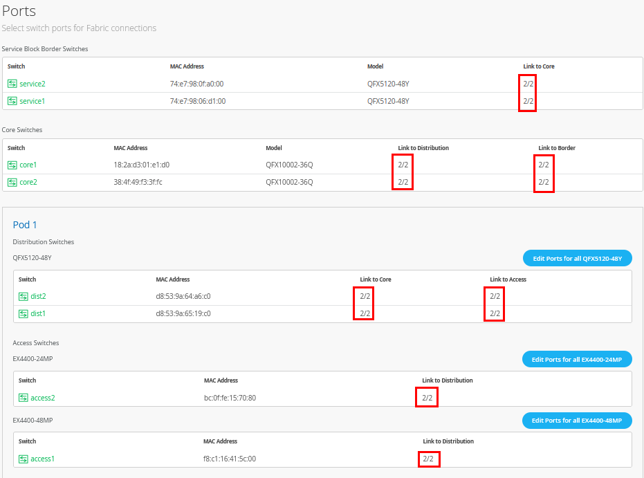
Confirm Your Topology
- Node=
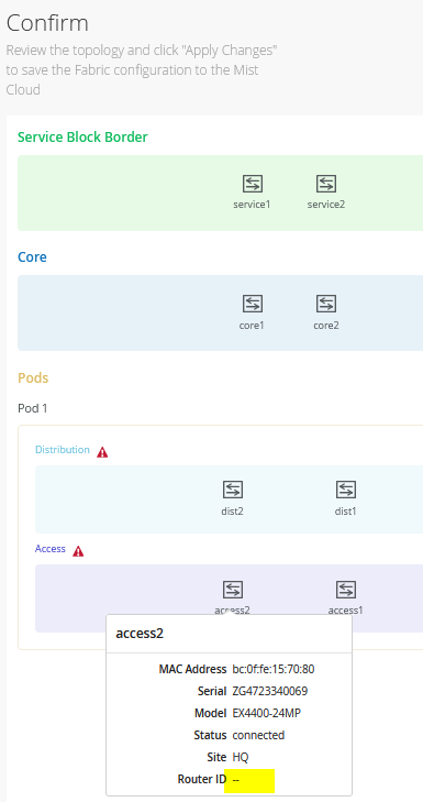
- Check your environment one last time before submitting the
final configuration. In the below figure, notice that the router ID
is still not assigned as this is a part of the first fabric
configuration. Ignore this again.
Figure 30: Topology Check
Apply Changes
- Now we can finally Apply Changes.
Figure 31: Apply Changes to Fabric
Confirm the dialogue a last time.
Figure 32: Confirm Apply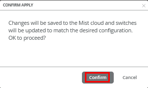
You must complete the second stage confirmation to create the fabric.
Juniper Mist displays the following banner including the estimated time for the campus fabric to be built. The process includes the following:
- Juniper Mist builds the point-to-point interfaces between service, core, distribution and access devices with IP addresses chosen from the range presented at the onset of the build.
- Each device is configured with a loopback address from the range presented at the onset of the build.
- eBGP is provisioned on each device with unique BGP autonomous system numbers. The primary goal of the underlay is to leverage ECMP for load balancing traffic on a per packet basis for device loopback reachability. The primary goal of the eBGP overlay is the support of customer traffic using EVPN-VXLAN.
- IP addressing of each L3 gateway IRB located on Access1 and Access2.
- IP addressing of each lo0.0 loopback, which is done automatically in this case.
- Configuration of routing policies for underlay and overlay connectivity.
- Optimized MTU settings for P2P underlay, L3 IRB, and ESI-LAG bundles.
- VXLAN-to-VLAN mapping using VNI addresses that are automatically assigned.
- VRF creation of corp-it, developers, and guest-wifi and VLAN associated with each VRF.
- VXLAN tunnelling creation between access devices and access-service block devices (in support of the northbound SRX WAN router that is configured in subsequent steps).
- Downloadable connection table (CSV format) that can be used by those involved in the physical buildout of the campus fabric.
- Graphical interface depicting all devices with BGP peering and physical link status.
You will now get the following message that your configuration was saved and the fabric will be built.
Figure 33: Fabric will be Built Now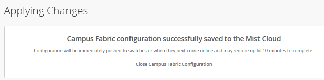 Note:
Note:As the dialogue window indicates, please wait 10 minutes before further actions.
- Once you click Close Campus Fabric Configuration, you can view a summary of the newly created campus fabric IP Clos.
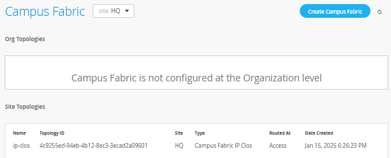
With Juniper Mist Wired Assurance, you can download a connection table (CSV format) representing the physical layout of the campus fabric. This can be used to validate all switch interconnects for those participating in the physical campus fabric build. Once the campus fabric is built or in the process of being built, you can download the connection table.
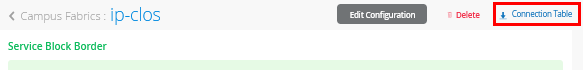
Connection Table spreadsheet:
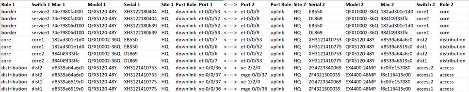
Apply VLANs to Access Ports
As previously discussed, Juniper Mist provides the ability to templatize well known services such as RADIUS, NTP, DNS, and so on that can be used across all devices within a site. These templates can also include VLANs and port profiles that can be targeted at each device within a site. The last step before verification is to associate VLANs with the requisite ports on each access switch.
In this case, Desktop1 to Desktop5 VMs and the access points are associated with different ports on each access switch which requires the configuration to be applied to Access1 and Access2, respectively. See Figure 1.
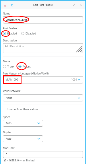
It is highly recommended that you use the switch template to define the port profiles as this will make them available automatically on all switches for port configuration. In our case, we need the following three Port Profiles defined.
- First Port Profile
- Name=
vlan1099-no-auth - Port Enabled=
Enabled - Mode=
Access - Port Network (Untagged/Native VLAN)=
VLAN1099
- Name=
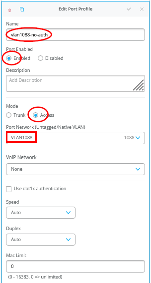
- Second Port Profile
- Name=
vlan1088-no-auth - Port Enabled=
Enabled - Mode=
Access - Port Network (Untagged/Native VLAN)=
VLAN1088
- Name=
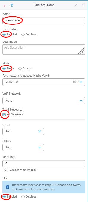
- Third Port Profile
- Name=
access-point - Port Enabled=
Enabled - Mode=
Trunk - Port Network (Untagged/Native VLAN)=
VLAN1033 - Trunk Networks=
All Networks - PoE=
Enabled
- Name=
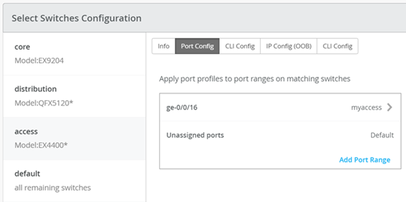
If most port configurations are the same across all access switches, a switch template can help to assign those port profiles automatically and you only need to take care of individual device configurations on each access switch. For example, the following found under the switch template option is customized to associate each switch with its role: service, core, distribution, and access. Furthermore, all access switches (defined by the EX4400 Switch, as an example) associated the AP port profile named “access-point” with ge-0/0/16 without needing to configure each independent switch.
In our lab however, those port configurations are too unique to use a switch template, hence we assign them individually to each access switch in the following configuration:
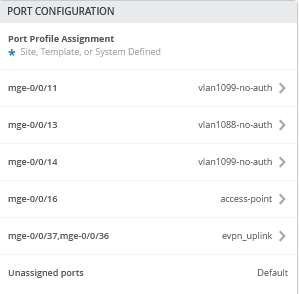
- Access Switch=
access1- Port1
- Interface=
mge-0/0/14 - Port Profile=
vlan1099-no-auth - Attached Lab function=
Desktop1 VM
- Interface=
- Port2
- Interface=
mge-0/0/13 - Port Profile=
vlan1088-no-auth - Attached Lab function=
Desktop3 VM
- Interface=
- Port3
- Interface=
mge-0/0/11 - Port Profile=
vlan1099-no-auth - Attached Lab function=
Desktop5 VM
- Interface=
- Port4
- Interface=
mge-0/0/16 - Port Profile=
access-point - Attached Lab function=
AP1
- Interface=
- Port1
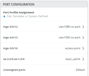
- Access Switch=
access2- Port1
- Interface=
mge-3/0/12 - Port Profile=
vlan1088-no-auth - Attached Lab function=
Desktop2 VM
- Interface=
- Port2
- Interface=
mge-3/0/13 - Port Profile=
vlan1099-no-auth - Attached Lab function=
Desktop4 VM
- Interface=
- Port3
- Interface=
mge-3/0/16 - Port Profile=
access-point - Attached Lab function=
AP2
- Interface=
- Port1
At this point, the WAN router integration has not happened yet. However, the DHCP server for the lab is only available through the WAN router using DHCP relay. As a result, no DHCP lease handouts to clients or access points will happen at this time.