ON THIS PAGE
Juniper RDMA-aware Load Balancing (LB) and BGP-DPF – Control Plane
Automatic GPU Server IPv6 Address Assignment Using SLAAC (Stateless Address Autoconfiguration)
Automatic link-local IPv6 address assignment and neighbor discovery on the leaf and spine nodes
BGP Session Auto-Discovery and BGP-DPF (Deterministic Path Forwarding)
Juniper RDMA-aware Load Balancing (LB) and BGP-DPF – Forwarding Plane
Juniper RDMA-aware Load Balancing (LB) and BGP-DPF – GPU Backend Fabric Operation
This section describes the operation details of the RDMA-aware Load Balancing (RLB) with BGP-DPF solution.
RDMA-aware Load Balancing (RLB) introduces deterministic path forwarding for AI workloads by combining Juniper Networks' BGP-DPF (Deterministic Path Forwarding) with advanced software integration at the host. This approach ensures that traffic flows follow pre-defined, consistent paths through the network fabric during steady-state operation, while maintaining robust fallback mechanisms in the event of failures.
In RoCEv2-based RDMA communication, a single large flow is often broken into multiple sub-flows, each associated with a distinct Queue Pair (QP). These sub-flows typically use the same source and destination IP addresses and destination UDP port (4791), differing only by their randomly chosen source ports. As a result, standard ECMP-based load balancing may hash multiple sub-flows to the same link, leading to uneven distribution and unpredictable performance.
RLB introduces determinism by assigning a unique IP address to each subflow, and using these IP addresses to steer the subflows across specific paths, instead of relying on hash-based load balancing which converts the load balancing challenge into a routing problem, where each RDMA sub-flow is mapped to a specific path through the fabric, eliminating randomness and ensuring consistent behavior and in-order delivery.
The solution ensures that each flow follows a pre-determined path through the network fabric:
- RDMA traffic is mapped to deterministic paths based on BGP export policies and color community tagging at the control plane, delivering highly predictable load distribution and forwarding for AI/ML workloads. By eliminating flow hashing, this method ensures in-order delivery and effectively prevents link congestion under steady-state conditions.
- This mapping eliminates the variability introduced by traditional hashing methods, enabling predictable flow distribution across all workloads.
- In the event of a link failure, the system automatically falls back to Dynamic Load Balancing (DLB), allowing traffic to reroute and complete the job with minimal disruption.
- Uses standard Ethernet, RoCEv2, and BGP protocol —no need for expensive NICs to do spraying or reordering.
Juniper RDMA-aware Load Balancing (LB) and BGP-DPF – Control Plane
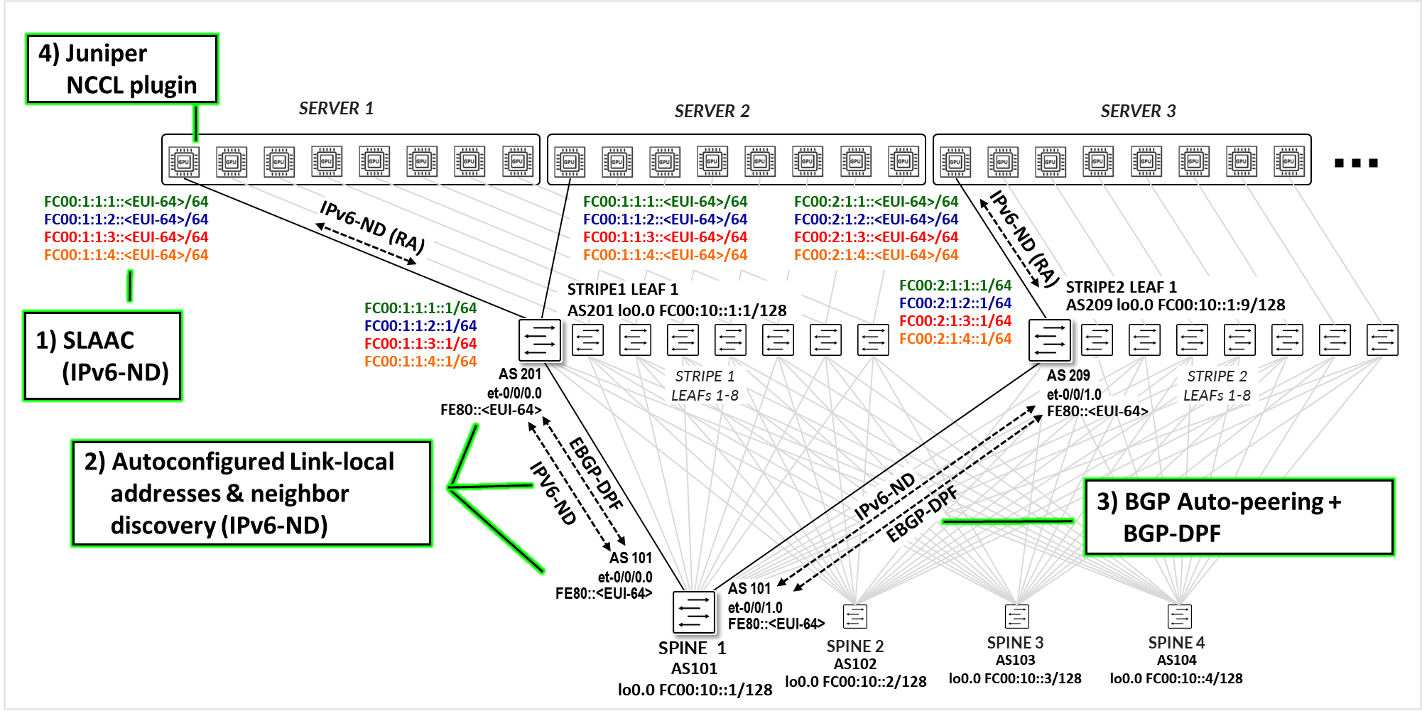
The control plane for this solution is built around four major components, as shown in Figure 1.
- Automatic Server IPv6 address assignment using SLAAC based on IPv6 Router Advertisements (IPv6-ND.
- Automatic link-local IPv6 address assignment on the leaf and spine nodes, combined with neighbor discovery using IPv6 Router Advertisements (IPv6-ND).
- Juniper EBGP-DPF using BGP neighbor auto-discovery (IPv6 link-local & neighbor discovery).
- Juniper NCCL plug-in on the servers.
Each component will be covered in detail in the next few sections.
Automatic GPU Server IPv6 Address Assignment Using SLAAC (Stateless Address Autoconfiguration)
To support scalable and automated IPv6 address assignment, the GPU servers obtain their IPv6 addresses using SLAAC. This not only eliminates the need to manually edit the netplan configuration files on each server but also provides the flexibility to add or remove IPv6 addresses as needed to support flow pinning to the network topology, especially since multiple IPv6 addresses per interface are required.
SLAAC (Stateless Address Autoconfiguration) is a mechanism defined in IPv6 that enables hosts to automatically generate their own IP addresses without requiring manual configuration or a DHCP server. The servers listen for Router Advertisement (RA) messages sent periodically by the connected leaf nodes. Leaf nodes must be explicitly configured to send RA messages on the downstream interfaces connected to the servers. These messages include an IPv6 prefix and flags indicating whether SLAAC should be used. The server then composes its IPv6 address by combining the advertised prefix with a 64-bit interface identifier, derived from its MAC address using the EUI-64 format. This approach enables efficient and scalable address provisioning, particularly in dynamic or large-scale environments.
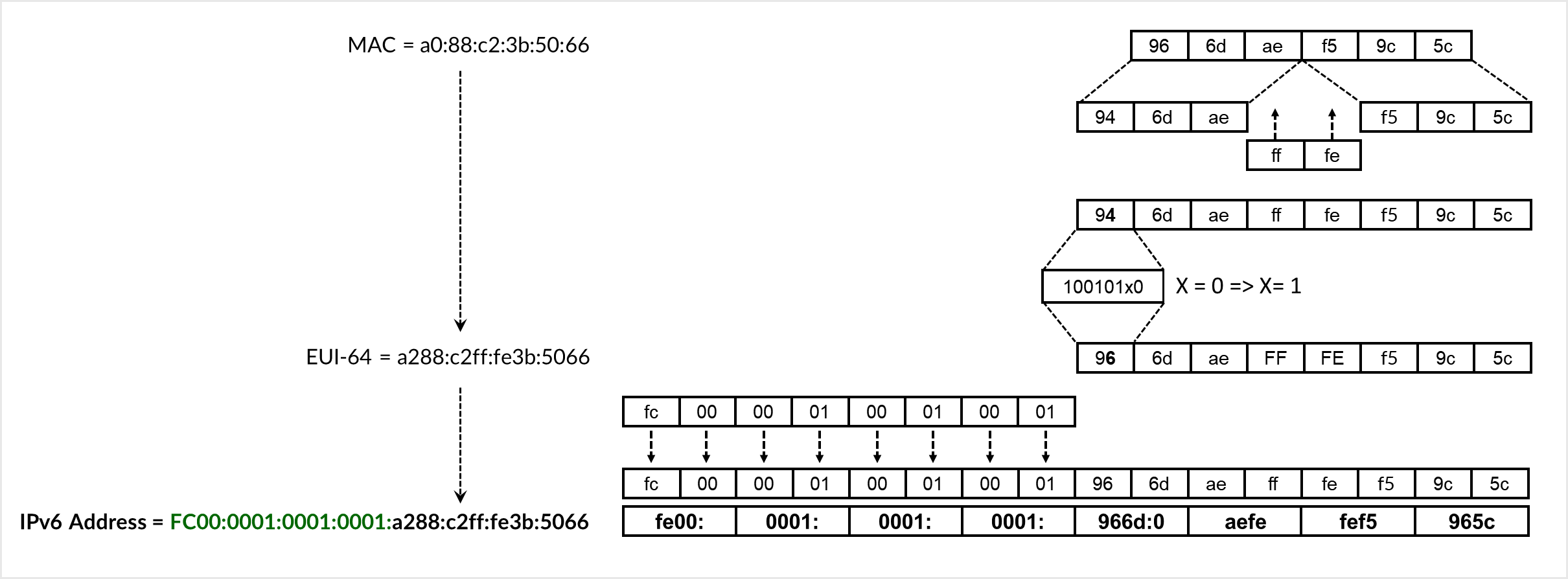
The EUI-64 conversion process involves splitting the 48-bit MAC address, inserting ff:fe in the middle, and flipping the Universal/Local (U/L) bit. As shown in Figure 2, the MAC address 96:6d:ae:f5:05:c0 is converted to the EUI-64 identifier 966d:aeff:fef5:05c0. The advertised prefix FC00:0000:0001:0001::/64 is then prepended to form the full IPv6 address FC00:0000:0001:0001:966d:aeff:fef5:05c0.
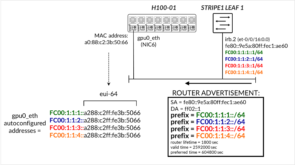
In the example depicted in Figure 3, Stripe 1 Leaf 1 interface irb.2 is configured with the IPv6 addresses FC00:1:1:1::1/64, FC00:1:1:2::1/64, FC00:1:1:3::1/64, and FC00:1:1:4::1/64. The interface also has a link-local address that was automatically generated from the interface’s MAC address. The switch is configured to send Router Advertisements (RAs) advertising the FC00:1:1:1::/64, FC00:1:1:2::/64, FC00:1:1:3::/64, and FC00:1:1:4::/64 prefixes. The server H100-01 then autoconfigures the corresponding IPv6 addresses on its gpu0_eth interface using its MAC address via SLAAC.
Notice that multiple IPv6 prefixes are being advertised on each interface. The number of prefixes, thus the number of IPv6 addresses assigned to each GPU server’s interface is dependent on the number of uplinks (connections between the leaf and spine nodes).
We recommend that you follow these guidelines:Number of queue pairs = Number of IPv6 address = Number of uplinks (leaf to spine links) . See the Recommended Number of Queue Pairs section for more detail.
The figure below illustrates a scenario with four spine nodes, showing either one link per leaf–spine connection or two links per connection. The goal is to have different IPv6 addresses for different flows, and then forward those flows across different paths based on their addresses.
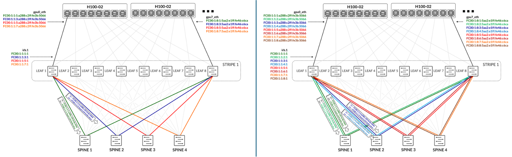
In the case with only one link per leaf–spine connection:
- Only four IPv6 addresses are necessary for each GPU interface.
- Traffic between the first IPv6 address assigned to gpu0_eth on Server 1 (H100-01) and the first IPv6 address assigned to gpu7_eth on Server 2 (H100-02) should be treated as green traffic and is forwarded across Spine 1.
- Traffic between the second IPv6 address assigned to gpu0_eth on Server 1 and the second IPv6 address assigned to gpu7_eth on Server 2 should be treated as blue traffic and is forwarded across Spine 2.
In the case with two links per leaf–spine connection:
- Eight IPv6 addresses are necessary for each GPU connection.
- Traffic between the first and second IPv6 addresses assigned to gpu0_eth on Server 1 and the first and second IPv6 addresses assigned to gpu7_eth on Server 2 should be treated as dark green and light green traffic, respectively, and is forwarded across Spine 1.
- Traffic between the third and fourth IPv6 addresses assigned to gpu0_eth on Server 1 and the third and fourth IPv6 addresses assigned to gpu7_eth on Server 2 should be treated as dark blue and light blue traffic, respectively, and is forwarded across Spine 2.
RDMA Flows will be mapped to the different IPv6 addresses on the server side. This will be described in the Juniper RDMA-aware Load Balancing (LB) and BGP-DPF – Forwarding Plane section.
Automatic link-local IPv6 address assignment and neighbor discovery on the leaf and spine nodes
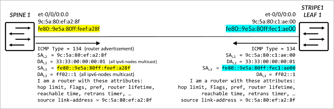
The interfaces between leaf and spine nodes do not require explicitly configured addresses. It is sufficient to enable IPv6 on each interface (e.g., by configuring family inet6). When IPv6 is enabled, the interface automatically generates a link-local IPv6 address in the fe80::/10 range, which can be used to communicate with directly connected neighbors. The link-local address is constructed using the EUI-64 format, in the same way servers construct their IPv6 address as part of SLAAC. This simplifies configuration and eliminates the need for manual IP addressing on leaf–spine links, while still allowing control plane protocols such as BGP to establish communication.
The leaf and spine nodes must be configured to send Router Advertisement (RA) messages on the interfaces that connect to one another, enabling automatic Neighbor Discovery. Each router advertises its own unique link-local address, along with additional information such as the MAC address, router lifetime, MTU, and other relevant options.
BGP Session Auto-Discovery and BGP-DPF (Deterministic Path Forwarding)
EBGP sessions between the leaf and spine nodes are automatically established once the devices learn each other’s link-local addresses through IPv6 Neighbor Discovery. This Juniper functionality, referred to as BGP auto-discovery or BGP auto-peering, leverages Junos OS support for:
- RFC 4861: Neighbor Discovery for IP version 6 (IPv6)
- RFC 2462: IPv6 Stateless Address Autoconfiguration
Traditionally, BGP requires explicit configuration of neighbor IPs, Autonomous System (AS) numbers, and routing policies to control route exchange. With BGP unnumbered peering, each node is configured to accept dynamic peers on designated interfaces. Sessions are formed between the link-local addresses that are automatically generated and exchanged via IPv6 Router Advertisements on point-to-point links. As a result, BGP sessions across the fabric can be established without manually defining neighbor IPs, simplifying deployment and improving scalability. Thus, the sessions are configured with minimal settings, including the local AS number, the list of acceptable remote AS numbers (for discovered peers), and IPv6 Neighbor Discovery.
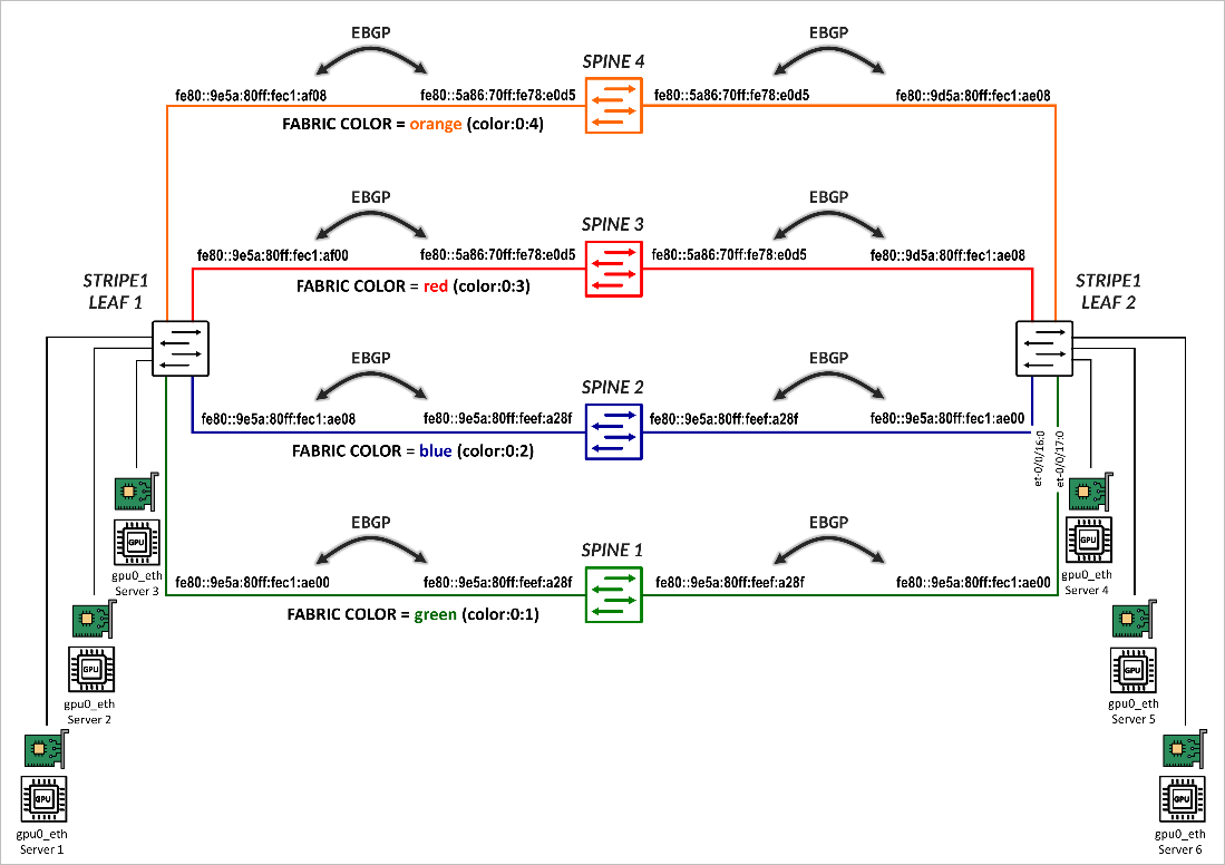
The sessions are also configured to act as BGP-DPF (Deterministic Path Forwarding) sessions, where each peer is associated with a fabric color, which defines the color assigned to the fabric path across that peer.
The colors are defined in the configuration under policy-options as BGP extended communities using the format color:0:<tag>. Some examples are shown in Table 1.
| Color (community) | Aggregate Prefix |
|---|---|
| green | color:0:1 |
| blue | color:0:2 |
| red | color:0:3 |
| orange | color:0:4 |
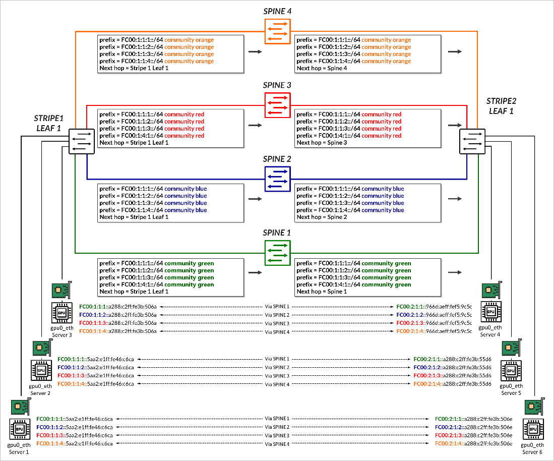
Once the BGP sessions are established, the same individual /64 IPv6 prefixes that each leaf node advertises to the GPU servers via Router Advertisements (RAs), as described in the GPU Server to Leaf Nodes Connections Using IPv6 SLAAC section . All prefixes are advertised to all the spines, tagged with the BGP color community that matches the corresponding fabric link color, as shown in Figure 7.
The AIGP BGP path attribute, is used to determine the prefix peer (path) for each prefix.
AIGP (Accumulated IGP) is a BGP path attribute defined in RFC 7311 that allows BGP to carry an accumulated metric, similar to an IGP cost, across BGP hops. When enabled, the AIGP value becomes part of the BGP best-path selection algorithm, specifically influencing decisions before the standard BGP tiebreakers (like router ID or shortest AS path).
In Junos, if the AIGP attribute is present, BGP will prefer the path with the lowest AIGP value. If AIGP is not present on a route, it is treated as having an effectively infinite cost, making it less preferred than any path that includes a valid AIGP value. For example, a route with AIGP = 1 is preferred over a route with no AIGP attribute.
Prefixes are advertised with an AIGP = 0 on preferred paths to the spine, and without an AIGP attribute on paths to all other spines as shown in the example in .
Figure 12: Prefix Advertisement with AIGP Example
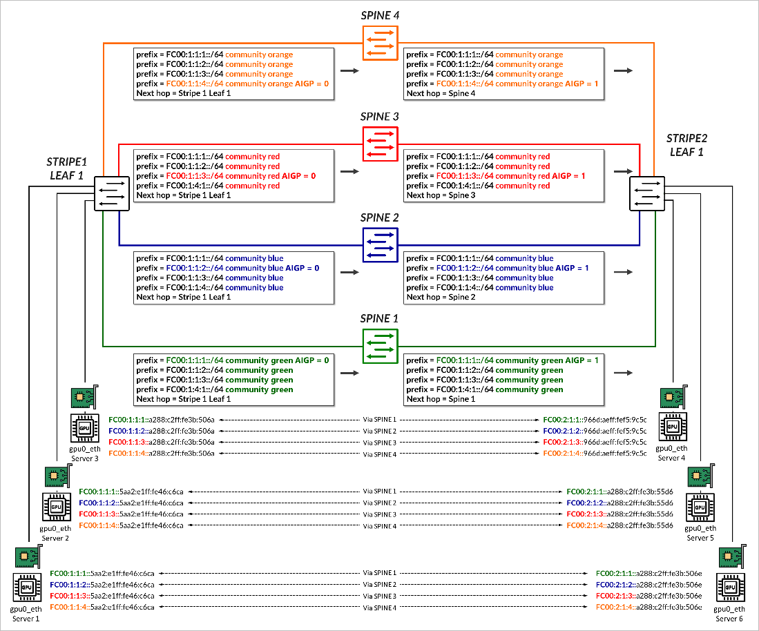
In the example, stripe1-leaf1 advertises the prefixes FC00:1:1:1::/64, FC00:1:1:2::/64, FC00:1:1:3::/64, and FC00:1:1:4::/64 to spines 1 through 4 with the color communities green, blue, red, and orange, respectively. Each prefix is sent with AIGP = 0 to a specific spine, as summarized in Table 2.
| PEER | ||||
|---|---|---|---|---|
| SPINE1 | SPINE2 | SPINE3 | SPINE4 | |
| ADVERTISED PREFIX | Color (community), AIGP VALUE | |||
| FC00:1:1:1::/64 | green, AIGP 0 | green | green | green |
| FC00:1:1:2::/64 | blue | blue, AIGP 0 | blue | blue |
| FC00:1:1:3::/64 | red | red | red, AIGP 0 | red |
| FC00:1:1:4::/64 | orange | orange | orange | orange, AIGP 0 |
Each spine then advertises all received prefixes to the remote leaf node without altering the community values, but an updated AIGP value of 1, reflecting the IGP cost from the spine to the original advertising leaf. As described before, all other routes are treated as having an infinite cost since no AIGP is present.
The receiving leaf node uses this information during BGP route selection. For example, stripe2-leaf1 receives four copies of the prefix FC00:1:1:1::/64, one from each spine, but selects the path received from Spine 1, as it has the lowest AIGP metric (1), as shown in Figure 8.
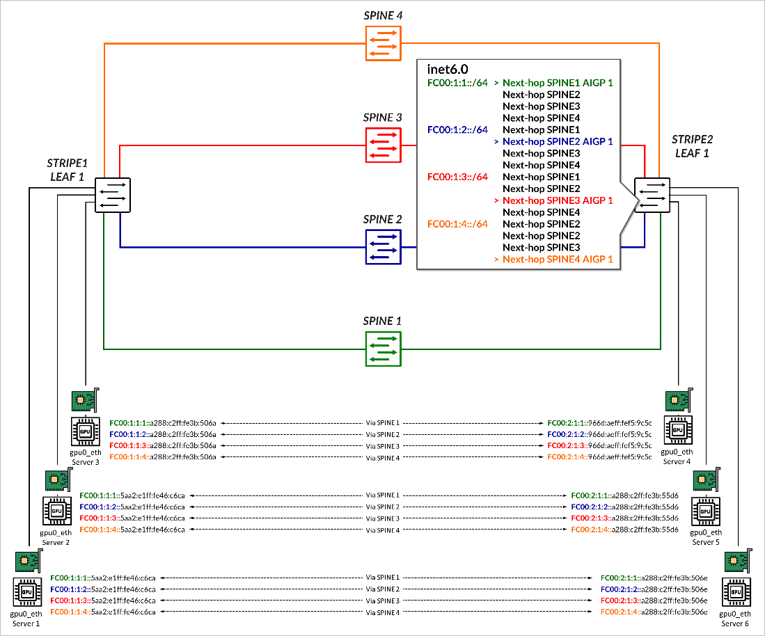
This allows for deterministic, per-prefix path selection that aligns with the forwarding intent of the advertising leaf. This will be shown in the Juniper RDMA-aware Load Balancing (LB) and BGP-DPF – Forwarding Plane section.
Juniper NCCL Plug-in on the Servers.
In typical RDMA implementations, when multiple Queue Pairs (QPs) are established between two endpoints, the resulting flows share the same protocol, source and destination IP addresses, and destination port (commonly UDP port 4791 for RoCEv2). The source ports are usually selected from a similar ephemeral range, resulting in very similar 5-tuples. With load-balancing mechanisms such as Equal-Cost Multi-Path (ECMP), traffic is hashed based on the 5-tuple, which determines the flow’s assignment to an egress interface. This often leads to multiple QPs being hashed to the same link. Enhancements like including QP identifiers in the hash or using Dynamic Load Balancing (DLB) based on congestion metrics can improve flow distribution. However, these mechanisms do not guarantee consistency, and flows may still be assigned to the same link. Additionally, reassignments caused by dynamic conditions can lead to out-of-order packet delivery and variable latency, which may negatively impact job performance.
To address these challenges, Juniper developed an NCCL network plugin — a shared library that extends NCCL’s native functionality by intercepting and customizing how RDMA connections are established and used. Rather than relying solely on NCCL’s built-in logic for device discovery, topology selection, and data movement, the plugin enables advanced features such as deterministic path selection and topology-aware traffic segmentation, tailored specifically for AI workloads over RoCEv2 fabrics.
The Juniper NCCL network plugin enables deterministic forwarding of RDMA traffic by splitting a single RDMA flow into multiple sub-flows. Each sub-flow is assigned a unique IPv6 address, generated via SLAAC, and mapped to a specific uplink on the ingress leaf switch. This allows traffic to be distributed deterministically and evenly across multiple interfaces. The use of distinct IPv6 addresses per Queue Pair (QP) ensures consistent path selection and is fully supported by modern NICs and network devices.
To implement this, the plugin partitions the memory region to be transferred into smaller segments, with each segment assigned to a different sub-flow, as shown in Figure 9. A separate RDMA Queue Pair (QP) is used for each segment.
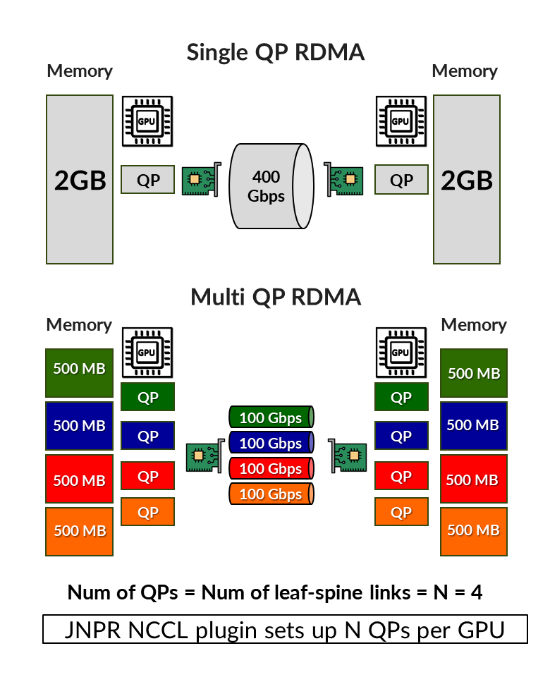
Sub-flows are transmitted concurrently. While packet ordering must be preserved within each sub-flow, there is no requirement for in-order delivery across different sub-flows. The next section describes how these sub-flows are handled by the forwarding plane, including how they are processed at each hop and how deterministic delivery is preserved across the fabric.
Recommended: Number of queue pairs = Number of IPv6 address = Number of uplinks (leaf to spine links). See the Recommended Number of Queue Pairs section for more details.
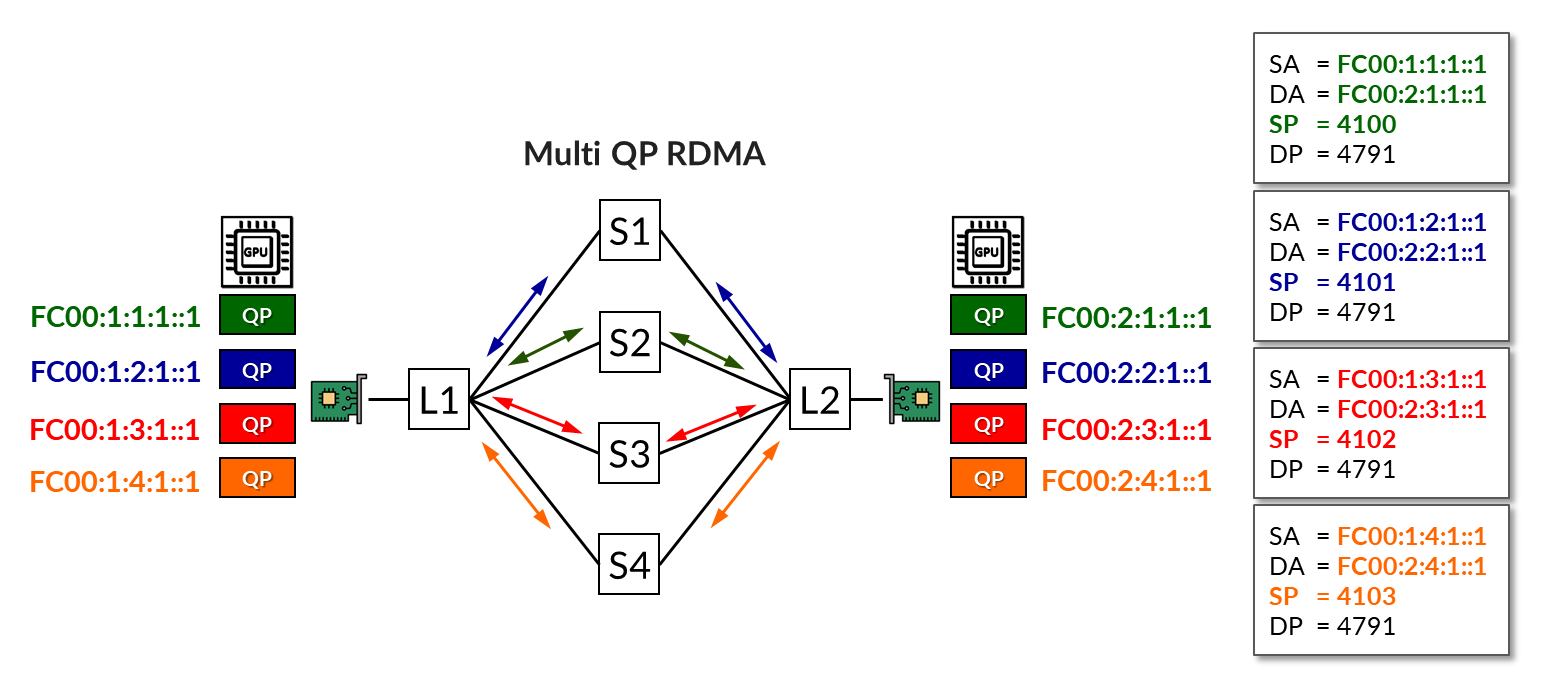
In the example shown in Figure 10, four QPs are in use. All four share the same protocol (UDP), source address (fc00:1:1:1::1), destination address (fc00:2:1:1::1), and destination port (4791), differing only in their source port numbers.
The load-balancing (without RLB) mechanism has assigned two of the flows across Spine 1 and the other two across Spine 3, leaving the paths through Spines 2 and 4 unused.
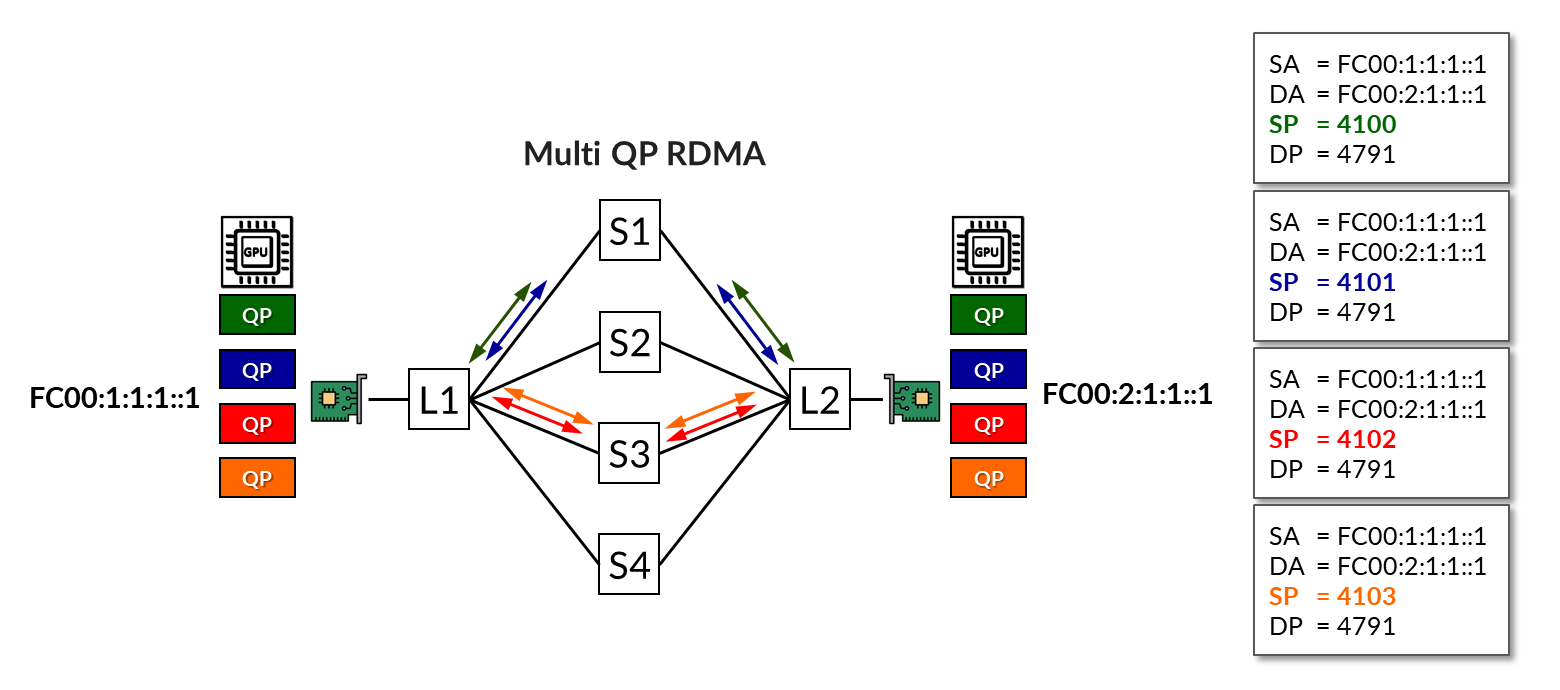
The same example but now using RLB is shown in Figure 11. In this scenario, multiple IPv6 addresses are assigned to each NIC, as described in the GPU Server to Leaf Nodes Connections Using IPv6 SLAAC section. Then, each QP is mapped to a different address. As a result, flows are deterministically assigned to specific uplinks based on BGP color communities and policy control, as described in the BGP Session Auto-Discovery and BGP-DPF (Deterministic Path Forwarding) section.
Juniper RDMA-aware Load Balancing (LB) and BGP-DPF – Forwarding Plane
Once the RDMA sub-flows are established and each one is mapped to a unique IPv6 source address, forwarding through the fabric follows the deterministic paths defined by the control plane. Each sub-flow, identified by its source and destination IPv6 addresses, is sent to the local leaf switch, which performs a forwarding table lookup. The available next hop, previously selected by the BGP decision process, causes the leaf to forward the packet deterministically toward the appropriate spine node.
When the spine receives the packet, it performs a route lookup and forwards the packet to the appropriate remote leaf node. Since the spine only maintains a single route per prefix, forwarding is consistent and deterministic.
At the remote leaf, the packet arrives from the spine and is forwarded to the destination GPU (NIC) associated with the target IPv6 address.
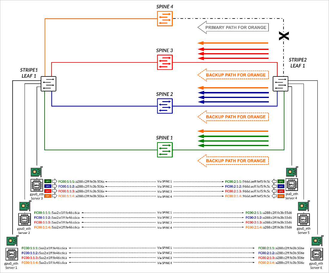
In the example shown in Figure 12, traffic for GPU0 QP1, is mapped to the IPv6 addresses FC00:1:1:4::a288:c2ff:fe3b:506a on Server 1, and to the IPv6 addresses FC00:2:1:4::966d:aeff:fef5:9c5c on Server 4. These two addresses correspond to prefix FC00:1:1:4::/64 and FC00:2:1:4::/64 respectively, which were advertised with the AIGP attribute across the path via Spine 4, as previously described in the BGP Session Auto-discovery and BGP-DPF (Deterministic Path Forwarding) section.
Traffic between these addresses is forwarded across the link to Spine 4, if available.
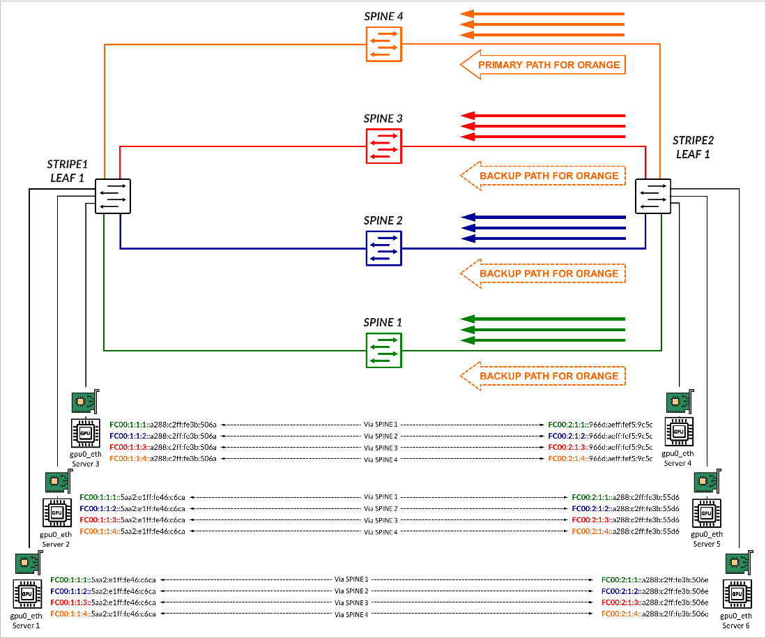
If there is failure, forwarding falls back to Dynamic Load Balancing (DLB). In the example, if the link to Spine 4 fails, the route disappears from the routing table and traffic destined to prefix FC00:1:1:4::/64, is forwarded across the other 3 paths (Back up paths) using DLB to balance the traffic. This is shown in Figure 13.