Juniper RDMA-aware Load Balancing (LB) and BGP-DPF – GPU Backend Fabric Implementation
This section outlines the configuration details to implement Juniper RDMA-aware Load Balancing (LB) and BGP-DPF. All configuration and verification examples in this section are based on the following example:
GPU Server to Leaf Nodes Connections Using IPv6 SLAAC (Stateless Address Autoconfiguration)
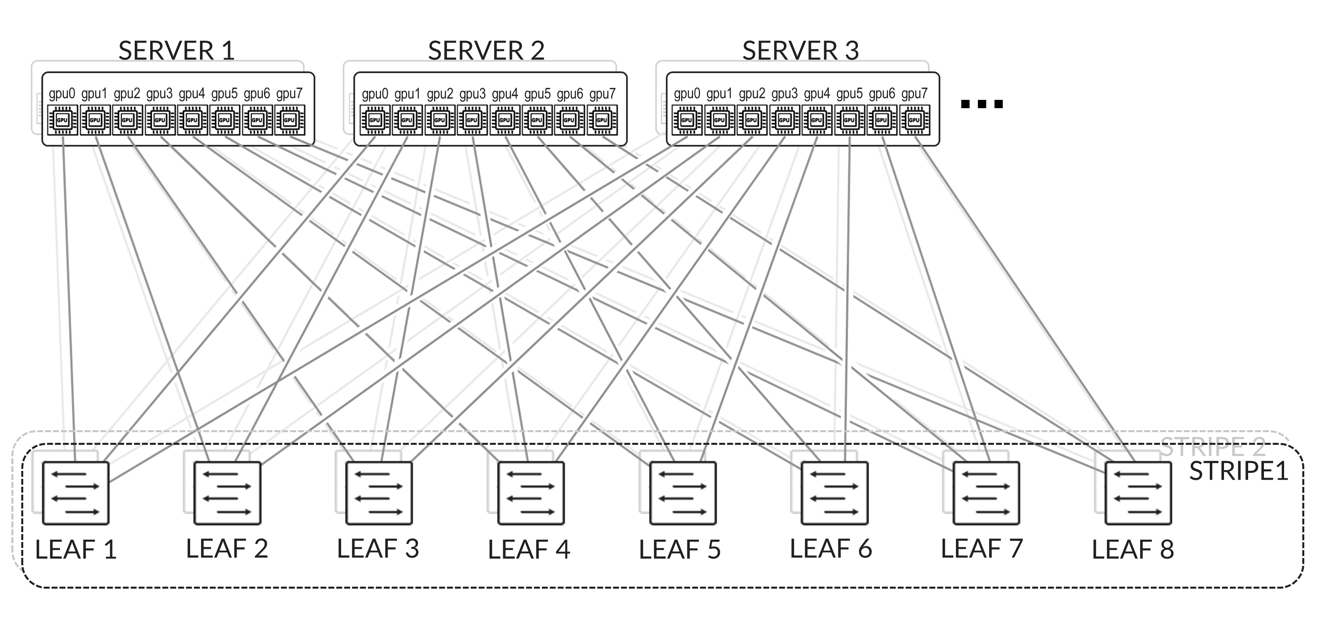
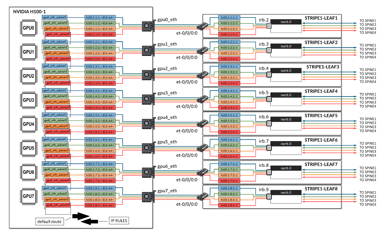
The GPU servers are connected following a rail-aligned architecture as described in the Backend GPU Rail Optimized Stripe Architecture section where GPU 0 on all the servers is connected to the first Leaf node, GPU 1 on all the servers is connected to the second Leaf node and so on. This is shown in Figure 2.
Connectivity between the servers and the leaf nodes is L2 vlan-based with an IRB on the leaf nodes acting as default gateway for the servers.
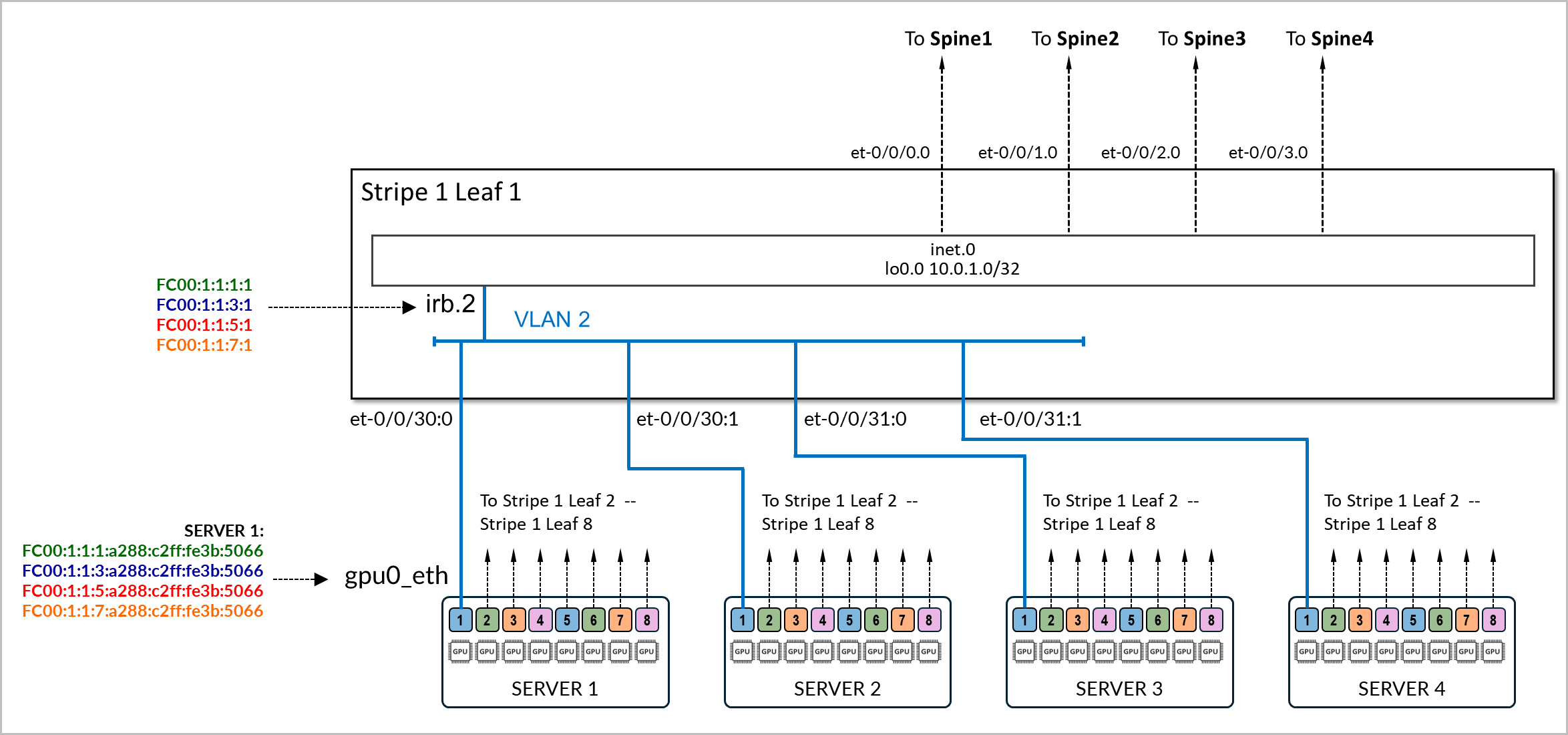
The physical interfaces connecting the servers and the leaf nodes are configured with family ethernet-switching and are mapped to a vlan with its associated irb as l3-interface.
Example:
The following example shows the configuration of the connection between stripe1-leaf1 and the gpu0_eth interfaces on Server 1 and Server 2. The irb.2 interface on the switch is configured with four /64 IPv6 addresses:
- fd00:1:1:1::1/64,
- fd00:1:1:2::1/64,
- fd00:1:1:3::1/64, and
- fd00:1:1:4::1/64.
These prefixes will be advertised to both server 1 and server 2.
[edit interfaces et-0/0/16:0]
jnpr@stripe1-leaf1# show
description to.h100-01:gpu0_eth;
native-vlan-id 2;
mtu 9216;
unit 0 {
    family ethernet-switching {
        interface-mode trunk;
        vlan {
            members vn2;
        }
}

[edit interfaces et-0/0/16:1]
jnpr@stripe1-leaf1# show
description to.h100-02:gpu0_eth;
native-vlan-id 2;
mtu 9216;
unit 0 {
    family ethernet-switching {
        interface-mode trunk;
        vlan {
            members vn2;
        }
}

[edit vlans vn2]
jnpr@stripe1-leaf1# show
description "Virtual network for rail 0 on leaf stripe1-leaf1";
vlan-id 2;
l3-interface irb.2;

[edit interfaces irb]
jnpr@stripe1-leaf1# show | display inheritance | except #
mtu 9216;
unit 2 {
    family inet6 {
        address fd00:1:1:1::1/64;
        address fd00:1:1:2::1/64;
        address fd00:1:1:3::1/64;
        address fd00:1:1:4::1/64;
    }

}
You can verify that the IPv6 addresses have been correctly assigned to the irb.2 interface and that it is associated with the proper VLAN using the following commands:
jnpr@stripe1-leaf1> show interfaces irb.2 terse
Interface               Admin Link Proto    Local                 Remote
irb.2                   up    up   inet6        fd00:1:1:1::1/64
                                                fd00:1:1:2::1/64
                                                fd00:1:1:3::1/64
                                                fd001:1:4::1/64
        fe80::9e5a:8000:2c1:b306/64
                                   multiservice
jnpr@stripe1-leaf1> show vlans vn2 detail
Routing instance: default-switch
VLAN Name: vn2                            State: Active
Tag: 2
Internal index: 4, Generation Index: 4, Origin: Static
Mac aging: Enabled
MAC aging time: 300 seconds
Layer 3 interface: irb.2
VXLAN Enabled : No
Interfaces:
    et-0/0/16:0.0*,untagged,trunk
    et-0/0/16:1.0*,untagged,trunk
Number of interfaces: Tagged 0    , Untagged 2
Total MAC count: 2
Server SLAAC Configuration:
To configure the interfaces on the NVIDIA GPU servers follow the steps in NVIDIA Configuration | Juniper Networks. You will need to ensure that the netplan includes statements to disable DHCPv6.
The interfaces on the servers do not need to be configured with any IPv6 address or have IPv6 explicitly enabled. Disabling DHCPv6 is enough.
Example:
gpu0_eth:
      match:
        macaddress: a0:88:c2:3b:50:66
      dhcp6: false
      mtu: 9000
      set-name: gpu0_eth
The following are netplan examples. You can use these examples to create templates to configure the addresses on all the servers.
jnpr@H100-01:/etc/netplan$ sudo cat 00-installer-config-type5_vrf.yaml
# This is the network config written by 'subiquity'
network:
  version: 2
  ethernets:
    mgmt_eth:
      match:
        macaddress: 6c:fe:54:48:2e:48
      dhcp4: false
      addresses:
        - 10.10.1.16/31
      nameservers:
        addresses:
        - 8.8.8.8
      routes:
        - to: default
          via: 10.10.1.17
      set-name: mgmt_eth
    gpu0_eth:
      match:
        macaddress: a0:88:c2:3b:50:66
      dhcp6: false
      mtu: 9000
      set-name: gpu0_eth
    gpu1_eth:
      match:
        macaddress: a0:88:c2:3b:50:6a
      dhcp6: false
      mtu: 9000
      set-name: gpu1_eth
    gpu2_eth:
      match:
        macaddress: a0:88:c2:3b:50:6e
      dhcp6: false
      mtu: 9000
      set-name: gpu2_eth
    gpu3_eth:
      match:
        macaddress: a0:88:c2:3b:50:72
      dhcp6: false
      mtu: 9000
      set-name: gpu3_eth
    gpu4_eth:
      match:
        macaddress: a0:88:c2:0a:79:48
      dhcp6: false
      mtu: 9000
      set-name: gpu4_eth
    gpu5_eth:
      match:
        macaddress: a0:88:c2:0a:79:4c
      dhcp6: false
      mtu: 9000
      set-name: gpu5_eth
    gpu6_eth:
      match:
        macaddress: a0:88:c2:0a:79:40
      dhcp6: false
      mtu: 9000
      set-name: gpu6_eth
    gpu7_eth:
      match:
        macaddress: a0:88:c2:0a:79:44
      dhcp6: false
      mtu: 9000
      set-name: gpu7_eth
    stor0_eth:
      match:
        macaddress: b8:3f:d2:63:e5:44
      dhcp6: false
      mtu: 9000
      routes:
        - to: 10.100.0.0/21
          via: 10.100.1.12
      set-name: stor0_eth
Make sure there is no IPv4 enabled on the gpu#_eth interfaces.
The servers must also be configured to accept and process RA messages, for IPv6 address autoconfiguration via Router Advertisements (RA) to work. In most cases, this will be enabled by default but the steps to configured are described here:
The configuration has two layers:
- Interface-level RA policy in Netplan or systemd
- Kernel-level sysctl parameters (accept_ra, autoconf)
Both must align to ensure proper RA behavior.
- If the system uses Netplan with systemd-networkd (common on Ubuntu Server):
In the Netplan YAML file (e.g., /etc/netplan/01-netcfg.yaml), add the following under each interface:
accept-ra: true
ipv6-privacy: false
Then apply the changes:
sudo netplan generate
sudo netplan apply
This ensures that Netplan renders a .network file for systemd-networkd with IPv6AcceptRA=yes, which enables RA-based autoconfiguration.
However, this alone is not enough. If the kernel is still configured to ignore RAs. You must also verify that the kernel is set to accept RAs at runtime. You can check using:
sudo sysctl net.ipv6.conf.<interface>.accept_ra
If the value is 0, RAs will be ignored regardless of Netplan settings. This can be temporarily corrected with:
sudo sysctl -w net.ipv6.conf.<interface>.accept_ra=1
To make it persistent across reboots, add the following to a sysctl configuration file (e.g., /etc/sysctl.d/99-accept-ra.conf):
net.ipv6.conf.<interface>.accept_ra = 1
And apply it with:
sudo sysctl --system
Parameters such as accept-ra can be enable or disable globally or on a per interface basis.
| SYSCTL | SCOPE | EFFECT |
|---|---|---|
| net.ipv6.conf.all.accept_ra | Global (all current interfaces) | Applies immediately to all existing interfaces, but... read-only if forwarding=1 |
| net.ipv6.conf.default.accept_ra | Global (for future interfaces) | Sets the default value used when a new interface comes up (e.g., plugged in or created later) |
| net.ipv6.conf.gpu0_eth.accept_ra | Per-interface | Controls RA processing for a specific active interface |
- If the interface is managed directly by the kernel (not using Netplan/systemd):
Enable RA acceptance and autoconfiguration by setting:
sudo sysctl -w net.ipv6.conf.<interface>.accept_ra=1
sudo sysctl -w net.ipv6.conf.<interface>.autoconf=1
sudo tee /etc/sysctl.d/99-ipv6-ra.conf > /dev/null <<EOF
net.ipv6.conf.<interface>.accept_ra = 1
net.ipv6.conf.<interface>.autoconf = 1
EOF
sudo sysctl --system
Leaf node SLAAC Configuration
To enable SLAAC, the Leaf nodes must be configured with IPv6 addresses on the GPU server facing interfaces.
Example:
jnpr@stripe1-leaf1# show interface irb
description "H100-01 GPU0 Server 1";
unit 2 {
    family inet6 {
        address FC00:1:1:1::1/64;
        address FC00:1:1:2::1/64;
        address FC00:1:1:3::1/64;
        address FC00:1:1:4::1/64;
    }
}
After configuring the IPv6 addresses, you must enable the advertisement of all prefixes, under protocol router-advertisement as shown in the example:
[edit protocols router-advertisement]
jnpr@stripe1-leaf1# show
	interface irb.2 {
	  prefix FC00:1:1:1::1/64;
  	prefix FC00:1:1:2::1/64;
  	prefix FC00:1:1:3::1/64;
	  prefix FC00:1:1:4::1/64;
}
Configuring router advertisements for a given prefix requires an IPv6 address within that same prefix to be configured on the interface where the router advertisements are configured. An error is return when committing the configuration if the prefix configured under router advertisements is not also configured under the interface.
Example:
[edit interfaces irb.2]
jnpr@stripe1-leaf1# show
unit 0 {
    family inet6 {
        address FC00:2:1:1::1/64;
    }
}
[edit protocols router-advertisement]
jnpr@stripe1-leaf1# show interface irb.2
 {
    prefix FC00:1:1:1::/64;
}
[edit protocols router-advertisement interface irb.2]
jnpr@stripe1-leaf1# commit
[edit protocols router-advertisement interface]
  'irb.2'
    Family inet6 should be configured on this interface
error: commit failed: (statements constraint check failed
The following table summarizes the prefixes and IP addresses on each irb interface, on each leaf node:
| IRB | VLAN | SUBNET 1 | IRB IP ADDRESS 1 | SUBNET 2 | IRB IP ADDRESS 2 | SUBNET 3 | IRB IP ADDRESS 3 | SUBNET 4 | IRB IP ADDRESS 4 | GPU INTERFACE | |
|---|---|---|---|---|---|---|---|---|---|---|---|
| STRIPE 1 LEAF 1 | 1 | 2 | fc00:1:1:1::/64 | fc00:1:1:1::1 | fc00:1:1:2::/64 | fc00:1:1:2::1 | fc00:1:1:3::/64 | fc00:1:1:3::1 | fc00:1:1:4::/64 | fc00:1:1:4::1 | gpu0_eth |
| STRIPE 1 LEAF 2 | 2 | 3 | fc00:1:2:1::/64 | fc00:1:2:1::1 | fc00:1:2:2::/64 | fc00:1:2:2::1 | fc00:1:2:3::/64 | fc00:1:2:3::1 | fc00:1:2:4::/64 | fc00:1:2:4::1 | gpu1_eth |
| STRIPE 1 LEAF 3 | 3 | 4 | fc00:1:3:1::/64 | fc00:1:3:1::1 | fc00:1:3:2::/64 | fc00:1:3:2::1 | fc00:1:3:3::/64 | fc00:1:3:3::1 | fc00:1:3:4::/64 | fc00:1:3:4::1 | gpu2_eth |
| STRIPE 1 LEAF 4 | 4 | 5 | fc00:1:4:1::/64 | fc00:1:4:1::1 | fc00:1:4:2::/64 | fc00:1:4:2::1 | fc00:1:4:3::/64 | fc00:1:4:3::1 | fc00:1:4:4::/64 | fc00:1:4:4::1 | gpu3_eth |
| STRIPE 1 LEAF 5 | 5 | 6 | fc00:1:5:1::/64 | fc00:1:5:1::1 | fc00:1:5:2::/64 | fc00:1:5:2::1 | fc00:1:5:3::/64 | fc00:1:5:3::1 | fc00:1:5:4::/64 | fc00:1:5:4::1 | gpu4_eth |
| STRIPE 1 LEAF 6 | 6 | 7 | fc00:1:6:1::/64 | fc00:1:6:1::1 | fc00:1:6:2::/64 | fc00:1:6:2::1 | fc00:1:6:3::/64 | fc00:1:6:3::1 | fc00:1:6:4::/64 | fc00:1:6:4::1 | gpu5_eth |
| STRIPE 1 LEAF 7 | 7 | 8 | fc00:1:7:1::/64 | fc00:1:7:1::1 | fc00:1:7:2::/64 | fc00:1:7:2::1 | fc00:1:7:3::/64 | fc00:1:7:3::1 | fc00:1:7:4::/64 | fc00:1:7:4::1 | gpu6_eth |
| STRIPE 1 LEAF 8 | 8 | 9 | fc00:1:8:1::/64 | fc00:1:8:1::1 | fc00:1:8:2::/64 | fc00:1:8:2::1 | fc00:1:8:3::/64 | fc00:1:8:3::1 | fc00:1:8:4::/64 | fc00:1:8:4::1 | gpu7_eth |
| STRIPE 2 LEAF 1 | 9 | 10 | fc00:2:1:1::/64 | fc00:2:1:1::1 | fc00:2:1:2::/64 | fc00:2:1:2::1 | fc00:2:1:3::/64 | fc00:2:1:3::1 | fc00:2:1:4::/64 | fc00:2:1:4::1 | gpu0_eth |
| STRIPE 2 LEAF 2 | 10 | 11 | fc00:2:2:1::/64 | fc00:2:2:1::1 | fc00:2:2:2::/64 | fc00:2:2:2::1 | fc00:2:2:3::/64 | fc00:2:2:3::1 | fc00:2:2:4::/64 | fc00:2:2:4::1 | gpu1_eth |
| STRIPE 2 LEAF 3 | 11 | 12 | fc00:2:3:1::/64 | fc00:2:3:1::1 | fc00:2:3:2::/64 | fc00:2:3:2::1 | fc00:2:3:3::/64 | fc00:2:3:3::1 | fc00:2:3:4::/64 | fc00:2:3:4::1 | gpu2_eth |
| STRIPE 2 LEAF 4 | 12 | 13 | fc00:2:4:1::/64 | fc00:2:4:1::1 | fc00:2:4:2::/64 | fc00:2:4:2::1 | fc00:2:4:3::/64 | fc00:2:4:3::1 | fc00:2:4:4::/64 | fc00:2:4:4::1 | gpu3_eth |
| STRIPE 2 LEAF 5 | 13 | 14 | fc00:2:5:1::/64 | fc00:2:5:1::1 | fc00:2:5:2::/64 | fc00:2:5:2::1 | fc00:2:5:3::/64 | fc00:2:5:3::1 | fc00:2:5:4::/64 | fc00:2:5:4::1 | gpu4_eth |
| STRIPE 2 LEAF 6 | 14 | 15 | fc00:2:6:1::/64 | fc00:2:6:1::1 | fc00:2:6:2::/64 | fc00:2:6:2::1 | fc00:2:6:3::/64 | fc00:2:6:3::1 | fc00:2:6:4::/64 | fc00:2:6:4::1 | gpu5_eth |
| STRIPE 2 LEAF 7 | 15 | 16 | fc00:2:7:1::/64 | fc00:2:7:1::1 | fc00:2:7:2::/64 | fc00:2:7:2::1 | fc00:2:7:3::/64 | fc00:2:7:3::1 | fc00:2:7:4::/64 | fc00:2:7:4::1 | gpu6_eth |
| STRIPE 2 LEAF 8 | 16 | 17 | fc00:2:8:1::/64 | fc00:2:8:1::1 | fc00:2:8:2::/64 | fc00:2:8:2::1 | fc00:2:8:3::/64 | fc00:2:8:3::1 | fc00:2:8:4::/64 | fc00:2:8:4::1 | gpu7_eth |
SLAAC Verification:
To verify that RA-based configuration works and the GPU interface has autoconfigured its IPv6 address and install corresponding routes, use the following commands:
ip -6 addr show dev <interface>
ip -6 route
You should see a global inet6 address in the SLAAC format (prefix::EUI-64) marked as dynamic or mngtmpaddr. You will also the interface’s link local address (FE80::EUI-64)
Example:
jnpr@H100-01:~$ ip -6 addr show dev gpu0_eth

17: gpu0_eth: <BROADCAST,MULTICAST,UP,LOWER_UP> mtu 9000 qdisc mq state UP group default qlen 1000
    inet6 fc00:1:1:1:a288:c2ff:fe3b:5066/64 scope global dynamic mngtmpaddr noprefixroute
       valid_lft 2591997sec preferred_lft 604797sec
    inet6 fc00:1:1:2:a288:c2ff:fe3b:5066/64 scope global dynamic mngtmpaddr noprefixroute
       valid_lft 2591997sec preferred_lft 604797sec
    inet6 fc00:1:1:3:a288:c2ff:fe3b:5066/64 scope global dynamic mngtmpaddr noprefixroute
       valid_lft 2591997sec preferred_lft 604797sec
    inet6 fc00:1:1:4:a288:c2ff:fe3b:5066/64 scope global dynamic mngtmpaddr noprefixroute
       valid_lft 2591997sec preferred_lft 604797sec
    inet6 fe80::a288:c2ff:fe3b:5066/64 scope link
       valid_lft forever preferred_lft forever

jnpr@H100-01:~$ ip -6 route
::1 dev lo proto kernel metric 256 pref medium
fc00:1:1:1::/64 dev gpu0_eth proto ra metric 100 expires 2591960sec pref medium
fc00:1:1:2::/64 dev gpu0_eth proto ra metric 100 expires 2591960sec pref medium
fc00:1:1:3::/64 dev gpu0_eth proto ra metric 100 expires 2591960sec pref medium
fc00:1:1:4::/64 dev gpu0_eth proto ra metric 100 expires 2591960sec pref medium
fe80::/64 dev stor0_eth proto kernel metric 256 pref medium
fe80::/64 dev mgmt_eth proto kernel metric 256 pref medium
fe80::/64 dev eno3 proto kernel metric 256 pref medium
fe80::/64 dev gpu0_eth proto kernel metric 256 pref medium
fe80::/64 dev gpu1_eth proto kernel metric 256 pref medium
fe80::/64 dev gpu2_eth proto kernel metric 256 pref medium
fe80::/64 dev gpu3_eth proto kernel metric 256 pref medium
fe80::/64 dev gpu4_eth proto kernel metric 256 pref medium
fe80::/64 dev gpu5_eth proto kernel metric 256 pref medium
fe80::/64 dev gpu6_eth proto kernel metric 256 pref medium
fe80::/64 dev gpu7_eth proto kernel metric 256 pref medium
default via fe80::9e5a:80ff:fec1:ae60 dev gpu0_eth proto ra metric 100 expires 1760sec pref medium

jnpr@stripe1-leaf1> show interfaces irb1 terse
Interface               Admin Link Proto    Local                 Remote
irb.1                   up    up
irb.1                   up    up   inet6    fc00:1:1:1::1/64
                                            fc00:1:1:2::1/64
                                            fc00:1:1:3::1/64
                                            fc00:1:1:4::1/64
                                            fe80::9e5a:80ff:fec1:ae60/64
                                   multiservice
You can also observe incoming RA messages with:
sudo tcpdump -i <interface> -vv icmp6 and 'ip6[40] == 134'
Example:
jnpr@H100-01:~$ sudo tcpdump -i gpu0_eth -vv icmp6 and 'ip6[40] == 134'
tcpdump: listening on gpu0_eth, link-type EN10MB (Ethernet), snapshot length 262144 bytes
18:34:50.515554 IP6 (flowlabel 0x9b92d, hlim 255, next-header ICMPv6 (58) payload length: 152) fe80::9e5a:80ff:fec1:ae60 > ip6-allnodes: [icmp6 sum ok] ICMP6, router advertisement, length 152
   hop limit 64, Flags [none], pref medium, router lifetime 1800s, reachable time 0ms, retrans timer 0ms
      source link-address option (1), length 8 (1): 9c:5a:80:c1:ae:60
        0x0000:  9c5a 80c1 ae60
      prefix info option (3), length 32 (4): fc00:1:1:1::/64, Flags [onlink, auto], valid time 2592000s, pref. time 604800s
        0x0000:  40c0 0027 8d00 0009 3a80 0000 0000 fc00
        0x0010:  0001 0004 0001 0000 0000 0000 0000
      prefix info option (3), length 32 (4): fc00:1:1:2::/64, Flags [onlink, auto], valid time 2592000s, pref. time 604800s
        0x0000:  40c0 0027 8d00 0009 3a80 0000 0000 fc00
        0x0010:  0001 0003 0001 0000 0000 0000 0000
      prefix info option (3), length 32 (4): fc00:1:1:3::/64, Flags [onlink, auto], valid time 2592000s, pref. time 604800s
        0x0000:  40c0 0027 8d00 0009 3a80 0000 0000 fc00
        0x0010:  0001 0002 0001 0000 0000 0000 0000
      prefix info option (3), length 32 (4): fc00:1:1:4::/64, Flags [onlink, auto], valid time 2592000s, pref. time 604800s
        0x0000:  40c0 0027 8d00 0009 3a80 0000 0000 fc00
        0x0010:  0001 0001 0001 0000 0000 0000 0000
In some cases, especially after changing RA settings or switching between static and dynamic configurations, the interface may need to be reset to trigger address reassignment:
sudo ip addr flush dev <interface>
sudo ip link set <interface> down && sleep 1 && sudo ip link set <interface> up
After bringing the interface back up, wait a few seconds and re-check the IPv6 address with:
ip -6 addr show dev <interface>
This ensures that stale addresses are removed, and fresh RAs are processed.
All IPv6 settings can be found under: /proc/sys/net/ipv6/conf .
To verify that router advertisements are being sent, you can use the following
command:show ipv6 router-advertisement interface <interface>.
Example:
jnpr@stripe1-leaf1> show ipv6 router-advertisement interface et-0/0/16:0
Interface: et-0/0/16:0.0
  Advertisements sent: 2, last sent 00:02:17 ago
  Solicits sent: 1, last sent 00:02:46 ago
  Solicits received: 0
  Advertisements received: 0
  Solicited router advertisement unicast: Disable
  IPv6 RA Preference: DEFAULT/MEDIUM
  Passive mode: Disable
  Upstream mode: Disable
  Downstream mode: Disable
  Proxy blackout timer: Not Running
You can also capture router advertisement packets on the interface using:
monitor traffic interface et-0/0/16:0.0 extensive matching "icmp6 and ip6[40] == 134"
Example:
jnpr@stripe1-leaf1> monitor traffic interface et-0/0/16:0.0 extensive matching "icmp6 and ip6[40] == 134"
NOTE: MAC Addresses 00:00:00:00:00:00 are used when L2 header information in not available. For such packets, L2 headers are added by PFE when transmit and removed before being punted to RE
Local vib interface has IP 128.0.0.4.
reading from file -, link-type EN10MB (Ethernet)
18:37:24.682098 9c:5a:80:c1:ae:60 > 33:33:00:00:00:01, ethertype IPv6 (0x86dd), length 284: (flowlabel 0x9b92d, hlim 255, next-header ICMPv6 (58) payload length: 152) fe80::9e5a:80ff:fec1:ae60 > ff02::1: [icmp6 sum ok] ICMP6, router advertisement, length 152
  hop limit 64, Flags [none], pref medium, router lifetime 1800s, reachable time 0ms, retrans timer 0ms
    source link-address option (1), length 8 (1): 9c:5a:80:c1:ae:60
      0x0000:  9c5a 80c1 ae60
    prefix info option (3), length 32 (4): fc00:1:1:4::/64, Flags [onlink, auto], valid time 2592000s, pref. time 604800s
      0x0000:  40c0 0027 8d00 0009 3a80 0000 0000 fc00
      0x0010:  0001 0004 0001 0000 0000 0000 0000
    prefix info option (3), length 32 (4): fc00:1:1:3::/64, Flags [onlink, auto], valid time 2592000s, pref. time 604800s
      0x0000:  40c0 0027 8d00 0009 3a80 0000 0000 fc00
      0x0010:  0001 0003 0001 0000 0000 0000 0000
    prefix info option (3), length 32 (4): fc00:1:1:2::/64, Flags [onlink, auto], valid time 2592000s, pref. time 604800s
      0x0000:  40c0 0027 8d00 0009 3a80 0000 0000 fc00
      0x0010:  0001 0002 0001 0000 0000 0000 0000
    prefix info option (3), length 32 (4): fc00:1:1:1::/64, Flags [onlink, auto], valid time 2592000s, pref. time 604800s
      0x0000:  40c0 0027 8d00 0009 3a80 0000 0000 fc00
      0x0010:  0001 0001 0001 0000 0000 0000 0000
Notice that Router Advertisements are sent using the link local address of the Leaf node interfaces as source, the ipv6 all-nodes multicast address (FF02::1), next-header ICMPv6 (58). The following are the most relevant attributes for these:
| PARAMETER | VALUE | DESCRIPTION |
|---|---|---|
| Flags | onlink, auto |
Hosts can assume addresses in this prefix are on the local link. This prefix can be used for SLAAC (Stateless Address Auto Configuration). |
| Valid Lifetime | 2592000 | Prefix is valid for 30 days (used for reachability). |
| Preferred Lifetime | 604800 | Preferred lifetime of 7 days (after which it becomes deprecated for new connections). |
| router lifetime | 1800s | The router is considered a default gateway for 1800 seconds |
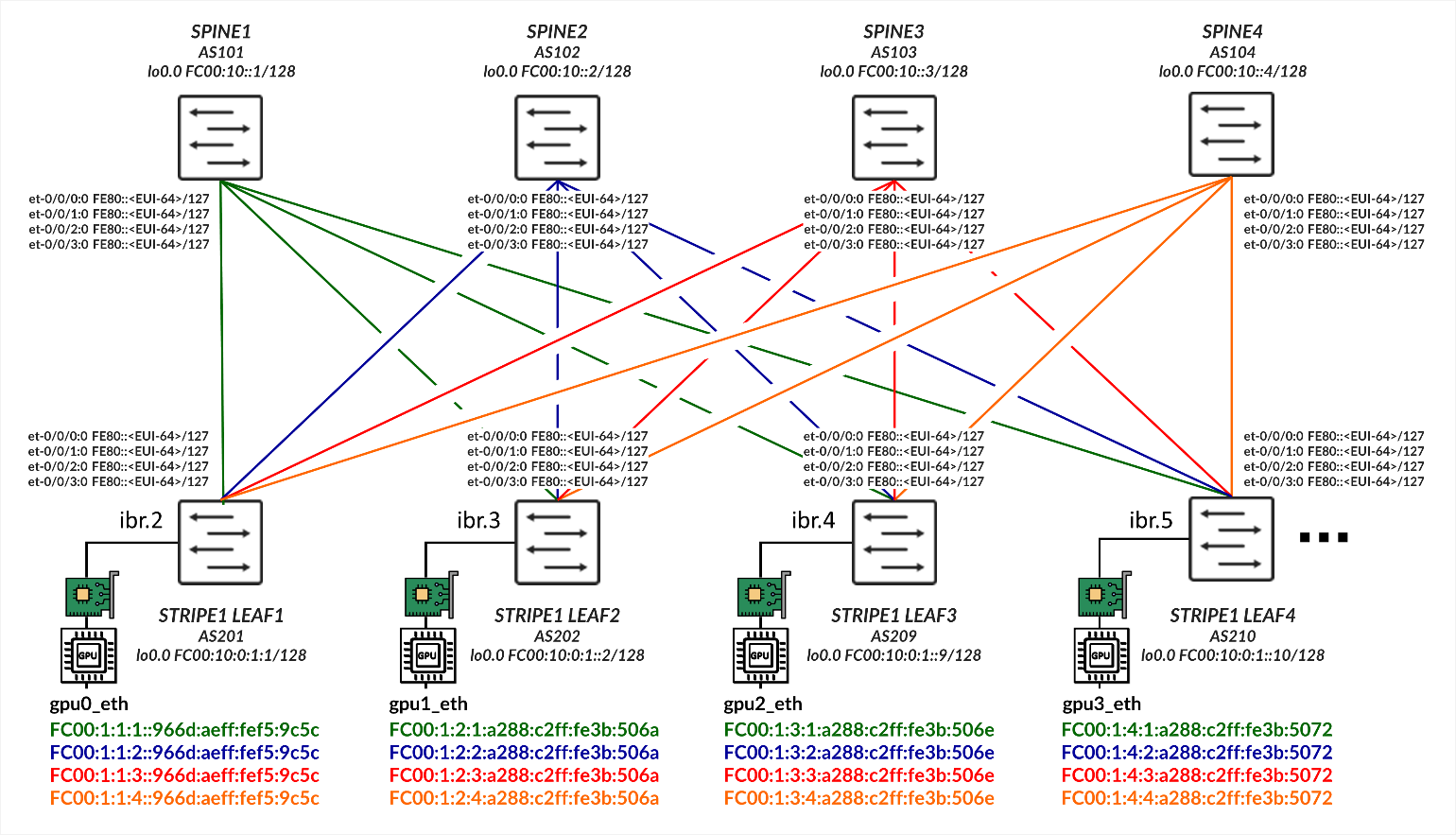
After receiving the router-advertisement, the server’s NIC interfaces will have autoconfigured their IPv6 addresses by concatenating the prefix advertise by the Leaf node, with the host portion of the address calculated using the EUI-64 address format (based on the interface’s MAC address), as shown in Table 4.
| LEAF NODE INTERFACE |
LEAF NODE IPv6 ADDRESS |
GPU NIC |
GPU NIC MAC address |
GPU NIC IPv6 ADDRESS |
||
|---|---|---|---|---|---|---|
| Stripe 1 Leaf 1 - et-0/0/16:0 |
fc00:1:1:1::1 fc00:1:1:2::1 fc00:1:1:3::1 fc00:1:1:4::1 |
Server 1 - gpu0_eth | a0:88:c2:3b:50:66 |
fc00:1:1:1:a288:c2ff:fe3b:5066 fc00:1:1:2:a288:c2ff:fe3b:5066 fc00:1:1:3:a288:c2ff:fe3b:5066 fc00:1:1:4:a288:c2ff:fe3b:5066 |
||
| Stripe 1 Leaf 1 - et-0/0/16:1 |
fc00:1:1:2::1 fc00:1:2:2::1 fc00:1:3:2::1 fc00:1:4:2::1 |
Server 2 - gpu0_eth | 58:a2:e1:46:c6:ca |
fc00:1:1:2:a288:c2ff:fe3b:506a fc00:1:2:2:a288:c2ff:fe3b:506a fc00:1:3:2:a288:c2ff:fe3b:506a fc00:1:4:2:a288:c2ff:fe3b:506a |
||
| Stripe 1 Leaf 1 - et-0/0/17:0 |
fc00:1:1:3::1 fc00:1:2:3::1 fc00:1:3:3::1 fc00:1:4:3::1 |
Server 3 - gpu0_eth | a0:88:c2:3b:50:6e |
fc00:1:1:3:a288:c2ff:fe3b:506e fc00:1:2:3:a288:c2ff:fe3b:506e fc00:1:3:3:a288:c2ff:fe3b:506e fc00:1:4:3:a288:c2ff:fe3b:506e |
||
|
. . . |
||||||
Leaf to Spine Connections using Link Local Addresses and IPv6 Neighbor Discovery
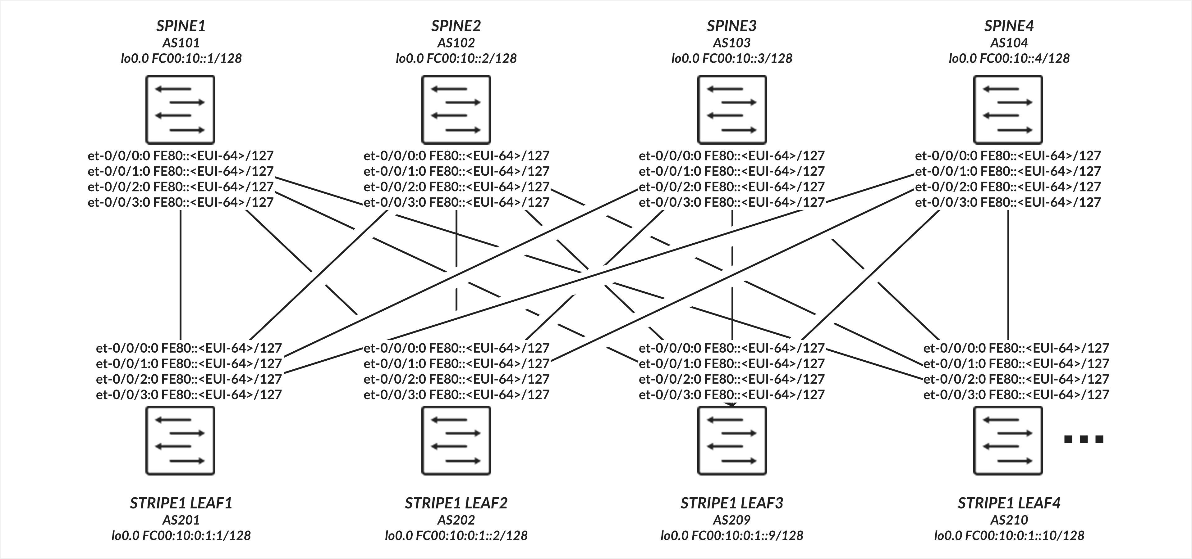
The interfaces between the leaf and spine nodes do not require explicitly configured IP addresses and are configured as untagged interfaces with only family inet6 to enable processing of IPv6 traffic. The interfaces automatically generate their link local addresses using EUI-64 format, as shown in Figure 4.
Leaf to Spine Connections Configuration
Table: Leaf to Spine Interface Configuration Example
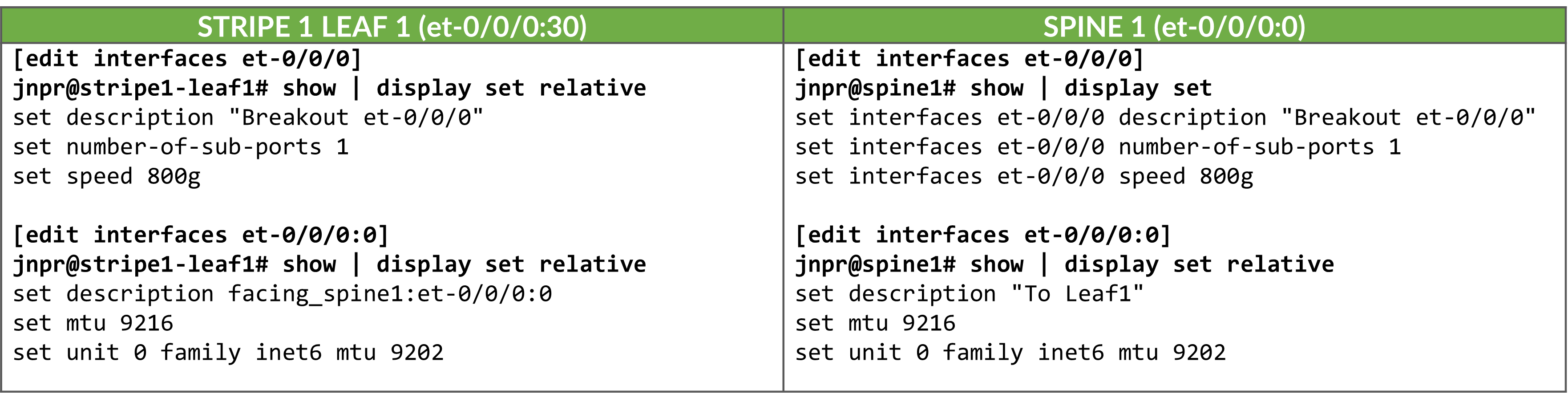
Enabling IPv6 on an interface automatically assigns a link-local IPv6 address. The switch autogenerates link local addresses for each interface using the EUI-64 address format (based on the interface’s MAC address), as shown in Table 5.
| LEAF NODE INTERFACE | LEAF NODE IPv6 ADDRESS | SPINE NODE INTERFACE | SPINE IPv6 ADDRESS |
|---|---|---|---|
| Stripe 1 Leaf 1 - et-0/0/0:0 | fe80::9e5a:80ff:fec1:ae00/64 | Spine 1 – et-0/0/0:0 | fe80::9e5a:80ff:feef:a28f/64 |
| Stripe 1 Leaf 1 - et-0/0/1:0 | fe80::9e5a:80ff:fec1:ae08/64 | Spine 2 – et-0/0/1:0 | fe80::5a86:70ff:fe7b:ced5/64 |
| Stripe 1 Leaf 1 - et-0/0/2:0 | fe80::9e5a:80ff:fec1:af00/64 | Spine 3 – et-0/0/2:0 | fe80::5a86:70ff:fe78:e0d5/64 |
| Stripe 1 Leaf 1 - et-0/0/3:0 | fe80::9e5a:80ff:fec1:af08/64 | Spine 4 – et-0/0/3:0 | fe80::5a86:70ff:fe79:3d5/64 |
| Stripe 1 Leaf 2 - et-0/0/0:0 | fe80::5a86:70ff:fe79:dad5/64 | Spine 1 – et-0/0/0:0 | fe80::9e5a:80ff:feef:a297/64 |
| Stripe 1 Leaf 2 - et-0/0/1:0 | fe80::5a86:70ff:fe79:dadd/64 | Spine 2 – et-0/0/1:0 | fe80::5a86:70ff:fe7b:cedd/64 |
| Stripe 1 Leaf 2 - et-0/0/2:0 | fe80::5a86:70ff:fe79:dbd5/64 | Spine 3 – et-0/0/2:0 | fe80::5a86:70ff:fe78:e0dd/64 |
| Stripe 1 Leaf 2 - et-0/0/3:0 | fe80::5a86:70ff:fe79:dbdd/64 | Spine 4 – et-0/0/3:0 | fe80::5a86:70ff:fe79:3dd/64 |
|
. . . |
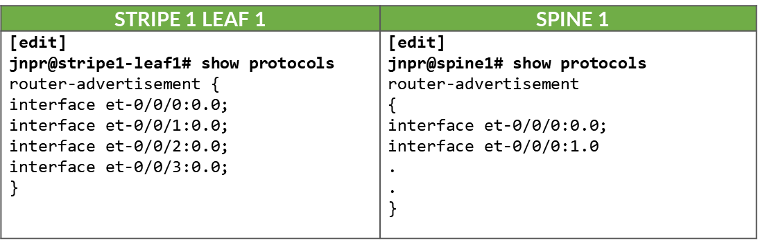
These addresses are advertised through standard router advertisements, as part of the IPv6 Neighbor Discovery process, after router advertisements have been enabled on all the interfaces between the leaf and spine nodes as shown:
Table:. IPv6 Router Advertisement on Leaf and Spine Interfaces
Leaf to Spine Connections Verification
To verify that router advertisements are being sent you can use show ipv6
router-advertisement interface <interface> and show ipv6
neighbors:
jnpr@stripe1-leaf1> show ipv6 router-advertisement interface et-0/0/0:0
Interface: et-0/0/0:0.0
  Advertisements sent: 4, last sent 00:02:28 ago
  Solicits sent: 1, last sent 00:08:06 ago
  Solicits received: 0
  Advertisements received: 3
  Solicited router advertisement unicast: Disable
  IPv6 RA Preference: DEFAULT/MEDIUM
  Passive mode: Disable
  Upstream mode: Disable
  Downstream mode: Disable
  Proxy blackout timer: Not Running
  Advertisement from fe80::9e5a:80ff:feef:a28f, heard 00:01:57 ago
    Managed: 0
    Other configuration: 0
    Reachable time: 0 ms
    Default lifetime: 1800 sec
    Retransmit timer: 0 ms
    Current hop limit: 64

jnpr@stripe1-leaf1> show ipv6 neighbors
IPv6 Address 	Linklayer Address  State       Exp   Rtr  Secure  Interface
fe80::5a86:70ff:fe78:e0d5	58:86:70:78:e0:d5  reachable   11    yes  no      et-0/0/30:0.0
fe80::5a86:70ff:fe79:3d5	58:86:70:79:03:d5  reachable   23    yes  no      et-0/0/3:0.0
fe80::5a86:70ff:fe7b:ced5 	58:86:70:7b:ce:d5  reachable   13    yes  no      et-0/0/2:0.0
fe80::9e5a:80ff:feef:a28f	9c:5a:80:ef:a2:8f  reachable   25    yes  no      et-0/0/31:0.0
Total entries: 4
BGP DPF (Deterministic Path Forwarding) Using IPv6 Neighbor Discovery
This section describes how to configure BGP to establish peering sessions between the leaf and spine nodes automatically, using IPv6 neighbor discovery, and how to enable Deterministic Patch Forwarding. It includes other BGP configuration parameters.
BGP Auto-discovery
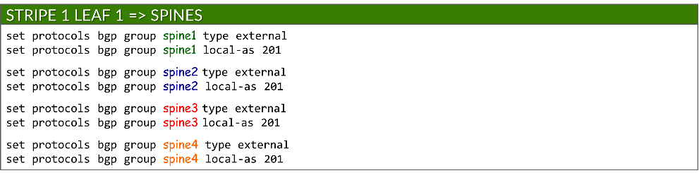
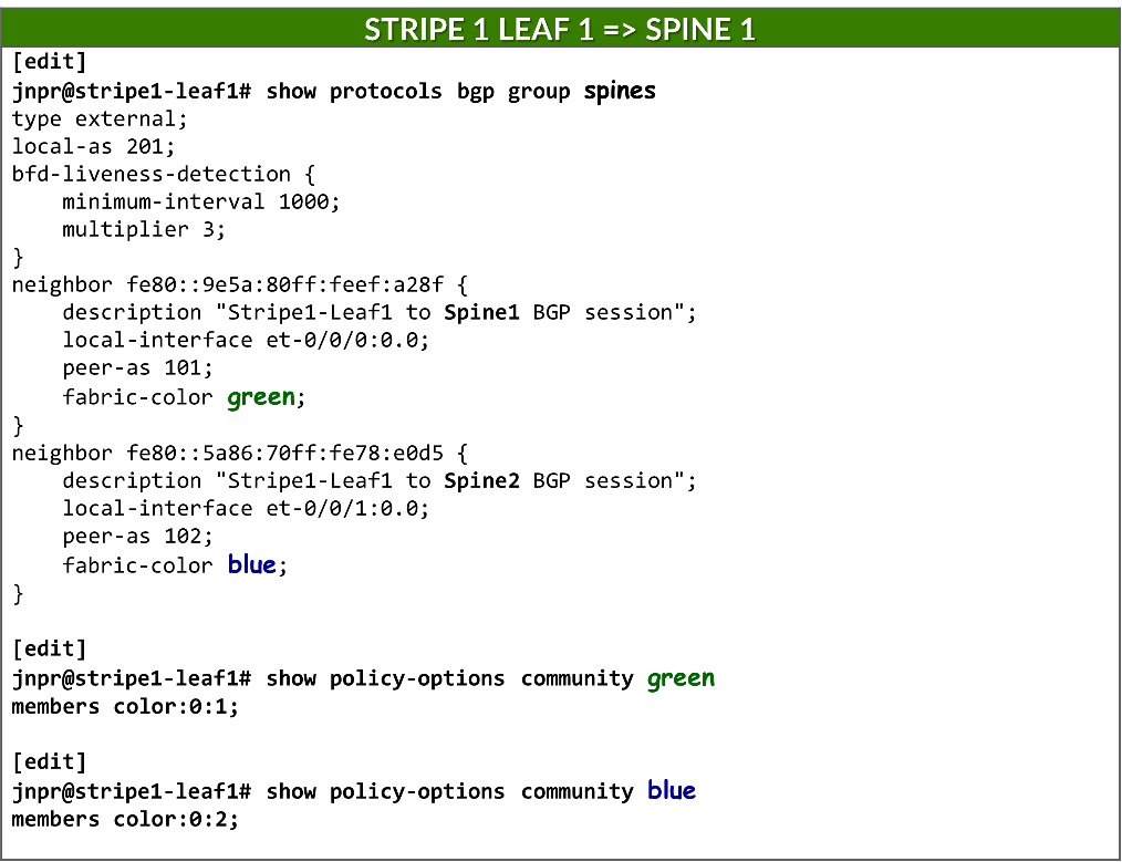
Because each connection between a leaf and spine node must be mapped to a different fabric color, and BGP is configured for auto-discovery, a separate BGP group per neighbor is required. This ensures that each dynamically discovered peer is associated with the correct color.
Each BGP group is configured as an external BGP session and assigned a local AS number:
set protocols bgp group <group-name> type external
set protocols bgp group <group-name> local-as <local-as#>
Example:
To enable BGP peer auto-discovery, each group includes a dynamic-neighbor template, which specifies the interface(s) where discovery is permitted. This replaces the traditional neighbor a.b.c.d configuration used for static peers. Auto-discovery is enabled using the peer-auto-discovery and ipv6-nd options:
set protocols bgp group <group-name> dynamic-neighbor <template-name> peer-auto-discovery interface <interface-name>
set protocols bgp group <group-name> dynamic-neighbor <template-name> peer-auto-discovery family inet6 ipv6-nd
Example:
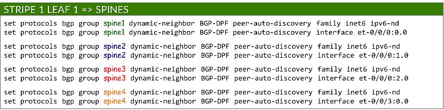
This allows Junos to determine neighbor addresses dynamically using IPv6 Neighbor Discovery.
To secure peer formation, each group references a defined AS range using the peer-as-list statement. This ensures that only neighbors with matching AS numbers can establish BGP sessions. The list itself is defined under policy-options:
set protocols bgp group <group-name> peer-as-list <as-list-name>
set policy-options as-list <aslist-name> members <value> | <value1-valueN> | [value1,value2,…]
Auto-discovery must be enabled on both the leaf and spine nodes.
Example:
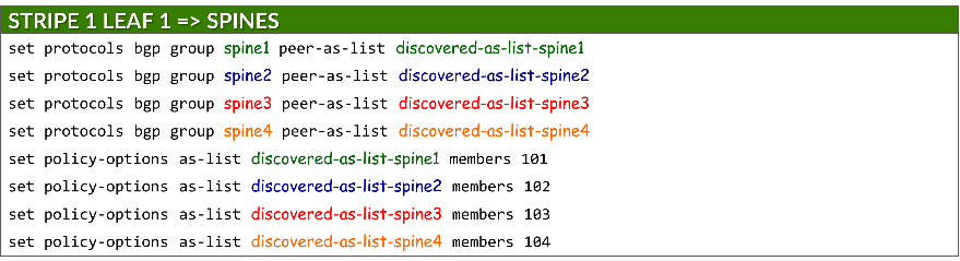
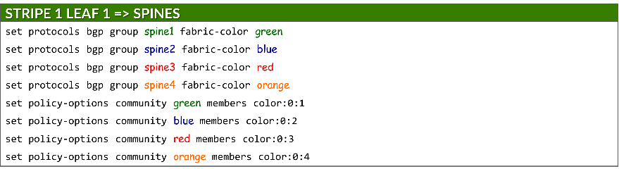
Each group is also assigned a fabric color, which is defined as a BGP community under policy-options:
set protocols bgp group <group-name> fabric-color <color>
set policy-options community <community-name> members color:0:<#>
where: <community-name> = <color>
IPv6 NLRI support
The advertisement of IPv6 routes must be enabled on both leaf and spine nodes using:
set protocols bgp family inet6 unicast
ECMP multipath
BGP multipath must be configured to allow Equal-Cost Multipath (ECMP) routing over protected path, ensuring both load balancing and failover across multiple spine uplinks. This is achieved using:
set protocols bgp group multipath allow-protection
BGP multipath must be configured on both leaf and spine nodes.
BFD (Bidirectional Forwarding Detection)
BFD is configured to improve failure detection time using:
set protocols bgp group <group-name> bfd-liveness-detection minimum-interval <interval>
set protocols bgp group <group-name> bfd-liveness-detection multiplier <multiplier>
| Options | Description |
|---|---|
|
minimum-interval (required) |
minimum time (in milliseconds) between BFD hello packets sent by the local device and the expected from the neighbor. Range: 1-255,000 Recommended value: 1000 |
|
multiplier (Optional) |
number of hello packets not received by a neighbor that causes the originating interface to be declared down. Range: 1-255 Recommended: 3 (default) |
BFD must be configured on both the leaf and spine nodes.
DPF (Deterministic Path Forwarding)
The leaf nodes must be configured to advertise the same individual /64 IPv6 prefixes advertised to the GPU servers via Router Advertisements (RAs), as described in the GPU Server to Leaf Nodes Connections Using IPv6 SLAAC section .
Prefixes are advertised using the fabric-advertise statement:
set protocols bgp fabric-advertise route <ipv6-prefix> color <color>
set protocols bgp fabric-advertise route <ipv6-prefix> backup-color <backup-color>
The fabric-advertise commands are only needed on the leaf nodes.
The color option specifies that the prefix should be advertised to BGP peers matching <color>. The prefix is advertised tagged with the community value associated with <color> and with the AIGP attribute set to 0. The backup-color option specifies that the prefix should be advertised to BGP peers matching <backup-color>. The advertised prefix is tagged with the community value associated with the peer, but without the AIGP attribute.
Example:
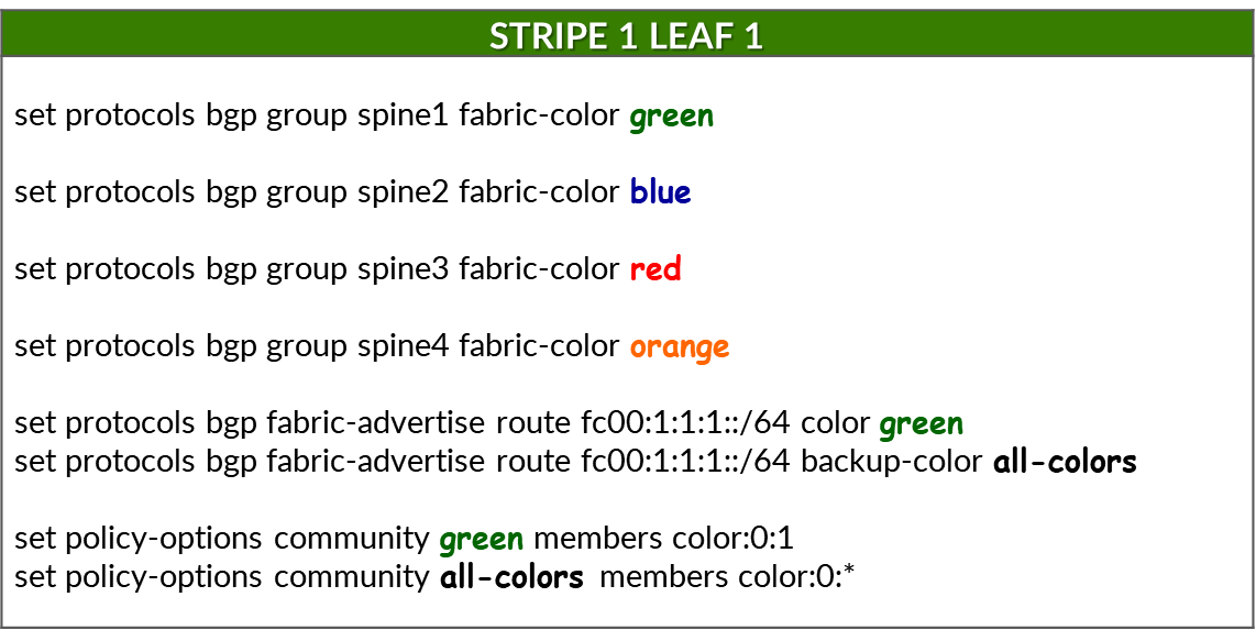
The following commands assign fabric colors to each BGP peer (i.e., each SPINE node when configured on a leaf node):
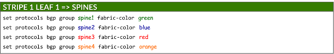
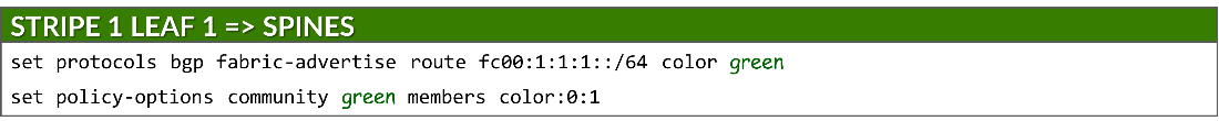
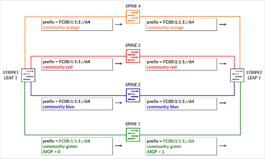
To advertise a prefix (fc00:1:1:1::/64) across the preferred path to reach that prefix, and assign the color green to the prefix, the following commands are used:
Make sure the correct prefixes are configured. No commit error is generated but prefixes will not be advertised.
This causes prefix fc00:1:1:1::/64 to be advertised to Spine 1. Because the color assigned to the prefix (green) matches the color of the peer (spine 1), the route is advertised with community color:0:1 (green) and includes the AIGP attribute, marking it as the preferred path.
To advertise the same prefix across all other paths (backup path), the following commands are used:
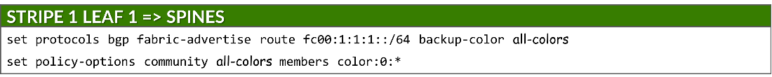
This causes the prefix to be advertised to all remaining spines, each tagged with its corresponding color community (blue, red, orange). Because the color assigned to the prefix (green) does not match the color of the peers (spines 2, 3 and 4), these advertisements do not include the AIGP attribute, ensuring they are less preferred.
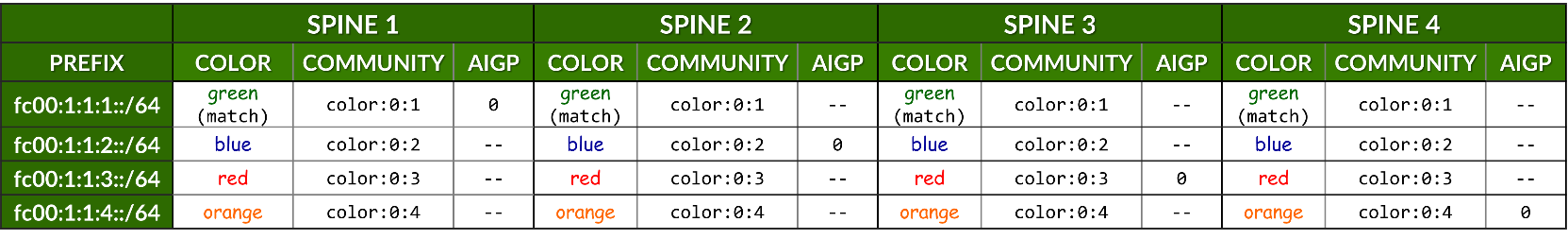
The following table summarizes the routing advertisement of prefix fc00:1:1:1::/64:
Table: Community and AIGP for Prefix fc00:1:1:1::/64
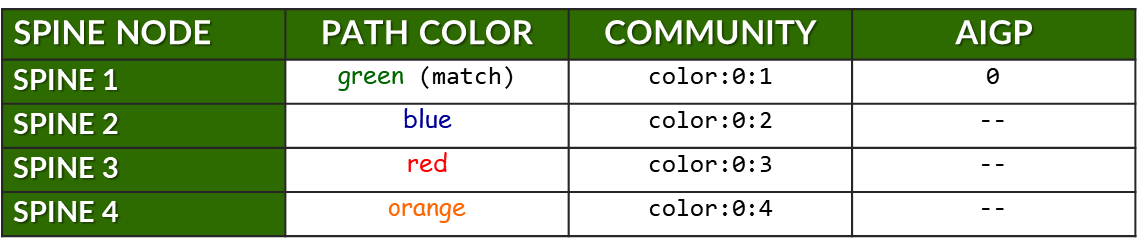
The previous example showed how a single prefix is advertised to all spine nodes, with only one spine receiving the route with the AIGP attribute to indicate the preferred path.
The table below expands on this by summarizing all prefixes advertised by stripe1-leaf1 (4) to all spine nodes. For each prefix, it shows:
- The assigned color for the intended path.
- The BGP community (color:0:X) used for tagging.
- Whether the AIGP attribute is included (for preferred path only).
Table: Community and AIGP Per Spine, Per Prefix Example
Example:
When neighbors are configured statically, the fabric-color can be configured directly under the neighbor statement, and therefore it is possible to have a single BGP group.
Preventing Route Re-advertisement to Spines
To configure the leaf nodes to advertise only the prefixes associated with the irb interface, and to prevent the advertisement of routes learned from one spine back to the other spine peers, an export policy is applied to all BGP groups. This ensures that the leaf acts as a non-transit node for spine-to-spine traffic and maintains proper routing in the fabric.
set policy-options policy-statement local term 1 from protocol direct
set policy-options policy-statement local term 1 from prefix-list-filter local orlonger
set policy-options policy-statement local term 1 then community add local
set policy-options policy-statement local term 1 then accept
set policy-options policy-statement local term 2 then reject
set policy-options prefix-list local fc00::/16
set policy-options prefix-list local fd00::/16
set policy-options community local members 201:201
This policy matches any route matching prefixes fc00::/16 and fd00::16 with a prefix length 16 bits or longer, and rejects it during export. Any additional IPv6 address to be advertised can be added to the prefix-list local.
Without this policy, a leaf node would re-advertise prefixes learned from one spine node to all the others, which could lead to unwanted routing behavior, and inefficient traffic distribution across the different paths.
jnpr@stripe1-leaf1> show route advertising-protocol bgp fe80::5a86:70ff:fe78:e0d5%et-0/0/1:0.0
inet6.0: 49 destinations, 85 routes (49 active, 0 holddown, 0 hidden)
Restart Complete
  Prefix                  Nexthop              MED     Lclpref    AS path
* fc00:1:1:1::/64         Self                                    I
* fc00:1:1:2::/64         Self                                    I
* fc00:1:1:3::/64         Self                                    I
* fc00:1:1:4::/64         Self                                    I
* fc00:1:2:1::/64         Self                                    101 202 I
* fc00:1:2:3::/64         Self                                    103 202 I
* fc00:1:2:4::/64         Self                                    104 202 I
* fc00:1:3:1::/64         Self                                    101 203 I
* fc00:1:3:3::/64         Self                                    103 203 I
* fc00:1:3:4::/64         Self                                    104 203 I
* fc00:1:4:1::/64         Self                                    101 204 I
* fc00:1:4:3::/64         Self                                    103 204 I
* fc00:1:4:4::/64         Self                                    104 204 I

[edit]
jnpr@stripe1-leaf1# set protocols bgp export local

[edit]
jnpr@stripe1-leaf1# commit
commit complete

jnpr@stripe1-leaf1> show route advertising-protocol bgp fe80::5a86:70ff:fe78:e0d5%et-0/0/1:0.0
inet6.0: 49 destinations, 85 routes (49 active, 0 holddown, 0 hidden)
Restart Complete
  Prefix                  Nexthop              MED     Lclpref    AS path
* fc00:1:1:1::/64         Self                                    I
* fc00:1:1:2::/64         Self                                    I
* fc00:1:1:3::/64         Self                                    I
* fc00:1:1:4::/64         Self                                    I
Additionally, routes are tagged with community local, which the spine nodes use to prevent
Additionally, routes are tagged with community local, which the spine nodes use to prevent advertising prefixes back to the leaf nodes.
[edit]
jnpr@spine1# show policy-options policy-statement leaf1 | display set
set policy-options policy-statement leaf1 term 1 from community leaf1
set policy-options policy-statement leaf1 term 1 then reject

jnpr@spine1# show policy-options community leaf1 | display set
set policy-options community leaf1 members 201:201
BGP Session Auto-discovery and DPF Verification
You can check that the sessions have been established by using
the
show bgp summary
command:
jnpr@stripe1-leaf1> show bgp summary
fe80::5a86:70ff:fe78:e0d5%et-0/0/1:0.0  	102         57         50       0       1       21:21 	Establ
  inet6.0: 0/0/0/0
fe80::5a86:70ff:fe79:3d5%et-0/0/2:0.0 	104         56         50       0       1       21:21 	Establ
  inet6.0: 0/0/0/0
fe80::5a86:70ff:fe7b:ced5%et-0/0/3:0.0 	103         56         50       0       1       21:21 	Establ
  inet6.0: 0/0/0/0
fe80::9e5a:80ff:feef:a28f%et-0/0/0:0.0    	101         24         18       0       2        6:55 	Establ
  inet6.0: 0/0/0/0
Notice that when BGP sessions are established using link-local
addresses Junos displays the neighbor address along with the
interface scope (e.g.
fe80::5a86:70ff:fe78:e0d5%et-0/0/1:0.0). The scope
identifier (the part after the %) is necessary because the same
link-local address (fe80::/10) could exist on multiple interfaces.
The device must know which interface to use to send
packets to that neighbor. Thus, after peer discovery is completed,
the
show bgp summary
output lists the
neighbor using the format:
IPv6_link-local_address%interface-name
You quickly check the status of the discovered neighbors using show bgp summary autodiscovered as shown in the example below:
jnpr@stripe1-leaf1> show bgp summary autodiscovered
Threading mode: BGP I/O
Default eBGP mode: advertise - accept, receive - accept
Groups: 4 Peers: 4 Down peers: 0
Auto-discovered peers: 4
Table          Tot Paths  Act Paths Suppressed    History Damp State    Pending
inet6.0
                      32          8          0          0          0          0
Peer                     AS      InPkt     OutPkt    OutQ   Flaps Last Up/Dwn State|#Active/Received/Accepted/Damped...
fe80::5a86:70ff:fe78:e0d5%et-0/0/1:0.0         102        176        179       0       0     1:17:12 Establ
  inet6.0: 3/12/12/0
fe80::5a86:70ff:fe79:3d5%et-0/0/3:0.0         104        528        528       0       2     3:55:54 Establ
  inet6.0: 3/12/12/0
fe80::5a86:70ff:fe7b:ced5%et-0/0/2:0.0         103        528        528       0       2     3:55:54 Establ
  inet6.0: 3/12/12/0
fe80::9e5a:80ff:feef:a28f%et-0/0/0:0.0         101        536        536       0       0     4:00:02 Establ
  inet6.0: 3/12/12/0
You can verify the status of a specific neighbor based on its fabric-color:
jnpr@stripe1-leaf1> show bgp summary fabric-color green
Threading mode: BGP I/O
Default eBGP mode: advertise - accept, receive - accept
Groups: 4 Peers: 3 Down peers: 0
Auto-discovered peers: 3
Table          Tot Paths  Act Paths Suppressed    History Damp State    Pending
inet6.0
                       0          0          0          0          0          0
Peer                     AS      InPkt     OutPkt    OutQ   Flaps Last Up/Dwn State|#Active/Received/Accepted/Damped...
fe80::9e5a:80ff:feef:a28f%et-0/0/0:0.0 101  301        300       0       0     2:14:08 Establ
  inet6.0: 3/12/12/0

jnpr@stripe1-leaf1> show bgp summary fabric-color blue
Threading mode: BGP I/O
Default eBGP mode: advertise - accept, receive - accept
Groups: 4 Peers: 4 Down peers: 0
Auto-discovered peers: 4
Table          Tot Paths  Act Paths Suppressed    History Damp State    Pending
inet6.0
                      32          8          0          0          0          0
Peer                     AS      InPkt     OutPkt    OutQ   Flaps Last Up/Dwn State|#Active/Received/Accepted/Damped...
fe80::5a86:70ff:fe78:e0d5%et-0/0/1:0.0         102        174        177       0       0     1:16:45 Establ
  inet6.0: 3/12/12/0

jnpr@stripe1-leaf1> show bgp summary fabric-color red
Threading mode: BGP I/O
Default eBGP mode: advertise - accept, receive - accept
Groups: 4 Peers: 3 Down peers: 0
Auto-discovered peers: 3
Table          Tot Paths  Act Paths Suppressed    History Damp State    Pending
inet6.0
                       0          0          0          0          0          0
Peer                     AS      InPkt     OutPkt    OutQ   Flaps Last Up/Dwn State|#Active/Received/Accepted/Damped...
fe80::5a86:70ff:fe7b:ced5%et-0/0/2:0.0 103  292        291       0       2     2:10:08 Establ
  inet6.0: 3/12/12/0

jnpr@stripe1-leaf1> show bgp summary fabric-color orange
Threading mode: BGP I/O
Default eBGP mode: advertise - accept, receive - accept
Groups: 4 Peers: 3 Down peers: 0
Auto-discovered peers: 3
Table          Tot Paths  Act Paths Suppressed    History Damp State    Pending
inet6.0
                       0          0          0          0          0          0
Peer                     AS      InPkt     OutPkt    OutQ   Flaps Last Up/Dwn State|#Active/Received/Accepted/Damped...
fe80::5a86:70ff:fe79:3d5%et-0/0/3:0.0 104  292        291       0       2     2:10:11 Establ
  inet6.0: 3/12/12/0

jnpr@stripe1-leaf1> show bgp neighbor auto-discovered
Peer: fe80::5a86:70ff:fe78:e0d5%et-0/0/1:0.0+179 AS 102 Local: fe80::9e5a:80ff:fec1:ae08%et-0/0/1:0.0+38208 AS 201
  Group: spine2                Routing-Instance: master
  Forwarding routing-instance: master
  Type: External    State: Established    Flags: <Sync PeerAsList AutoDiscoveredNdp>
  Last State: OpenConfirm   Last Event: RecvKeepAlive
  Last Error: None
  Export: [ local ]
  Options: <GracefulRestart AddressFamily Multipath LocalAS Refresh>
  Options: <BfdEnabled>
  Options: <GracefulShutdownRcv MultipathAllowProtection>
  Address families configured: inet6-unicast
  Holdtime: 90 Preference: 170
  Graceful Shutdown Receiver local-preference: 0
  Local AS: 201 Local System AS: 201
  Number of flaps: 0
  Receive eBGP Origin Validation community: Reject
  Peer ID: 10.0.0.2        Local ID: 10.0.1.1          Active Holdtime: 90
  Keepalive Interval: 30         Group index: 5    Peer index: 0    SNMP index: 33
  I/O Session Thread: bgpio-0 State: Enabled
  BFD: enabled, up
  Local Interface: et-0/0/1:0.0
  Fabric color: blue [color:0:2 ]
  NLRI for restart configured on peer: inet6-unicast
  NLRI advertised by peer: inet6-unicast
  NLRI for this session: inet6-unicast
  Peer supports Refresh capability (2)
  Restart time configured on the peer: 120
  Stale routes from peer are kept for: 300
  Restart time requested by this peer: 120
  Restart flag received from the peer: Notification
  NLRI that peer supports restart for: inet6-unicast
  NLRI peer can save forwarding state: inet6-unicast
  NLRI that peer saved forwarding for: inet6-unicast
  NLRI that restart is negotiated for: inet6-unicast
  NLRI of received end-of-rib markers: inet6-unicast
  NLRI of all end-of-rib markers sent: inet6-unicast
  Peer does not support LLGR Restarter functionality
  Peer supports 4 byte AS extension (peer-as 102)
  Peer does not support Addpath
  NLRI(s) enabled for color nexthop resolution: inet6-unicast
  Table inet6.0 Bit: 30003
    RIB State: BGP restart is complete
    Send state: in sync
    Active prefixes:              3
    Received prefixes:            12
    Accepted prefixes:            12
    Suppressed due to damping:    0
    Advertised prefixes:          4
  Last traffic (seconds): Received 1    Sent 3    Checked 10485
  Input messages:  Total 394    Updates 11      Refreshes 0     Octets 8605
  Output messages: Total 398    Updates 14      Refreshes 0     Octets 8874
  Output Queue[2]: 0            (inet6.0, inet6-unicast)
---more---

jnpr@stripe1-leaf1> show bgp neighbor fabric-color green
Peer: fe80::9e5a:80ff:feef:a28f%et-0/0/0:0.0+179 AS 101 Local: fe80::9e5a:80ff:fec1:ae00%et-0/0/0:0.0+49626 AS 201
  Group: spine1                Routing-Instance: master
  Forwarding routing-instance: master
  Type: External    State: Established    Flags: <Sync PeerAsList AutoDiscoveredNdp>
  Last State: OpenConfirm   Last Event: RecvKeepAlive
  Last Error: None
  Options: <GracefulRestart AddressFamily Multipath LocalAS Refresh>
  Options: <BfdEnabled>
  Options: <GracefulShutdownRcv MultipathAllowProtection>
  Address families configured: inet6-unicast
  Holdtime: 90 Preference: 170
  Graceful Shutdown Receiver local-preference: 0
  Local AS: 201 Local System AS: 201
  Number of flaps: 0
  Receive eBGP Origin Validation community: Reject
  Peer ID: 10.0.0.1        Local ID: 10.0.1.1          Active Holdtime: 90
  Keepalive Interval: 30         Group index: 4    Peer index: 0    SNMP index: 30
  I/O Session Thread: bgpio-0 State: Enabled
  BFD: enabled, up
  Local Interface: et-0/0/0:0.0
  Fabric color: green [color:0:1 ]
  NLRI for restart configured on peer: inet6-unicast
  NLRI advertised by peer: inet6-unicast
  NLRI for this session: inet6-unicast
  Peer supports Refresh capability (2)
  Restart time configured on the peer: 120
  Stale routes from peer are kept for: 300
  Restart time requested by this peer: 120
  Restart flag received from the peer: Notification
  NLRI that peer supports restart for: inet6-unicast
  NLRI peer can save forwarding state: inet6-unicast
  NLRI that peer saved forwarding for: inet6-unicast
  NLRI that restart is negotiated for: inet6-unicast
  NLRI of received end-of-rib markers: inet6-unicast
  NLRI of all end-of-rib markers sent: inet6-unicast
  Peer does not support LLGR Restarter functionality
  Peer supports 4 byte AS extension (peer-as 101)
  Peer does not support Addpath
  NLRI(s) enabled for color nexthop resolution: inet6-unicast
  Table inet6.0 Bit: 30001
    RIB State: BGP restart is complete
    Send state: in sync
    Active prefixes:              0
    Received prefixes:            0
    Accepted prefixes:            0
    Suppressed due to damping:    0
    Advertised prefixes:          4
  Last traffic (seconds): Received 14   Sent 2    Checked 7803
  Input messages:  Total 292    Updates 1       Refreshes 0     Octets 5607
  Output messages: Total 291    Updates 3       Refreshes 0     Octets 5797
  Output Queue[2]: 0            (inet6.0, inet6-unicast)

jnpr@stripe1-leaf1> show bfd session
                                                  Detect   Transmit
Address                  State     Interface      Time     Interval  Multiplier
fe80::9e5a:80ff:feef:a28f Up       et-0/0/0:0.0   3.000     1.000        3

1 sessions, 1 clients
Cumulative transmit rate 1.0 pps, cumulative receive rate 1.0 pps
To verify that the prefixes are advertised correctly to all peers use show route
advertising-protocol bgp <peer-address>.
jnpr@stripe1-leaf1> show route advertising-protocol bgp fe80::9e5a:80ff:feef:a28f%et-0/0/0:0.0 extensive
In the example, fe80::9e5a:80ff:feef:a28f%et-0/0/0:0.0 is the address of Spine 1.
Thus, all prefixes are advertised with community color:0:1 (green). fc00:1:1:1::/64 is also advertised with the AIGP attribute as it is also configured with the same color. The same prefix is also advertised to the other spines but without the AIGP value. fe80::5a86:70ff:fe78:e0d5%et-0/0/1:0.0 is the address of Spine 2.
fe80::5a86:70ff:fe7b:ced5%et-0/0/2:0.0 is the address of Spine 3.
fe80::5a86:70ff:fe79:3d5%et-0/0/3:0.0 is the address of Spine 4.
jnpr@stripe1-leaf1> show route fc00:1:1:1::/64 extensive advertising-protocol bgp fe80::9e5a:80ff:feef:a28f%et-0/0/0:0.0
inet6.0: 49 destinations, 85 routes (49 active, 0 holddown, 0 hidden)
Restart Complete
* fc00:1:1:1::/64 (1 entry, 1 announced)
 BGP group spine1 type External
     Nexthop: Self
     AS path: [201] I
     Communities: color:0:1
     AIGP: 0

jnpr@stripe1-leaf1> show route fc00:1:1:1::/64 extensive advertising-protocol bgp fe80::5a86:70ff:fe78:e0d5%et-0/0/1:0.0
inet6.0: 49 destinations, 85 routes (49 active, 0 holddown, 0 hidden)
Restart Complete
* fc00:1:1:1::/64 (1 entry, 1 announced)
 BGP group spine2 type External
     Nexthop: Self
     AS path: [201] I
     Communities: color:0:2

jnpr@stripe1-leaf1> show route fc00:1:1:1::/64 extensive advertising-protocol bgp fe80::5a86:70ff:fe7b:ced5%et-0/0/2:0.0
inet6.0: 49 destinations, 85 routes (49 active, 0 holddown, 0 hidden)
Restart Complete
* fc00:1:1:1::/64 (1 entry, 1 announced)
 BGP group spine3 type External
     Nexthop: Self
     AS path: [201] I
     Communities: color:0:3

jnpr@stripe1-leaf1> show route fc00:1:1:1::/64 extensive advertising-protocol bgp fe80::5a86:70ff:fe79:3d5%et-0/0/3:0.0
inet6.0: 49 destinations, 85 routes (49 active, 0 holddown, 0 hidden)
Restart Complete
* fc00:1:1:1::/64 (1 entry, 1 announced)
 BGP group spine4 type External
     Nexthop: Self
     AS path: [201] I
     Communities: color:0:4
Juniper NCCL Plug-in
The Juniper NCCL Net Plugin assigns a unique IPv6 address to each Queue Pair (QP) on every RDMA interface. This enables QP flows to use distinct source and destination addresses, allowing the fabric to forward them along separate paths. To support this behavior, the plugin and its supporting libraries must be installed, and the servers must be configured with additional routing information to ensure proper forwarding of each IPv6 address—both from the server to the leaf node and vice versa.
Installing the plug-in on the servers
The Juniper NCCL net plugin is distributed as a compressed tar-ball (juniper-ib_2.23.4-1.tar.gz) and can be found in …
To install, extract the tar-ball to the root directory:
$ tar -xzvf juniper-ib_0.0.5.tar.gz -C /
| COMPONENT | DESCRIPTION/USAGE |
|---|---|
| /usr/local/lib/libnccl-net-juniper-ib.so | The NCCL network plugin shared object |
| /usr/local/bin/jnpr-fabric-topo-gen | Script for generating fabric topology json file |
| /usr/local/bin/jnpr-AI-LB-dpf-config-gen | Script for generating AI-LB DPF configurations |
| /usr/local/bin/jnpr-nccl-net-setup | Tool for configuring GPU Server network settings |
| /usr/local/bin/gids.py | Helper module for finding GIDs |
| /usr/local/bin/jnpr-rdma-ping | Tool for testing RDMA connectivity |
| /usr/local/bin/jnpr-find-gids | Tool for finding GIDs. |
Configuring routing parameters on the GPUs servers
On the GPU servers, each IPv6 address assigned to an interface must be associated with a separate routing table, containing the appropriate routes to forward traffic through the correct default gateway. Conversely, IP rules must be created to direct incoming traffic destined for each specific IPv6 address to its corresponding routing table.
Therefore, when configuring the servers to operate correctly with the NCCL plugin for RDMA Load Balancing (RLB), you must create a number of routing tables equal to the number of IPv6 addresses assigned per interface (based on the number of uplinks, as previously described) multiplied by the number of NICs.
In the example shown in Figure 6, each interface is assigned four IPv6 addresses, resulting in a total of 32 routing tables. Each routing table must include a default route and a corresponding prefix route. Additionally, an IP rule must be added for each routing table.
The jnpr-nccl-net-setup utility live-run option can be used to automatically create the necessary tables, routes, and IP rules on each server.
jnpr@H100-01:/home/ijohnson/2.23.4-1/usr/local/bin$ jnpr-nccl-net-setup -h

Usage: jnpr-nccl-net-setup <subcommand> [--live-run] [--help | -h]

Subcommands:
    dual-stack    Enable dual stack (ipv4/ipv6) and accept router advertisements
    clos          Configure routes and rules for CLOS network
    rail          Configure routes and rules for Rail optimized network
    auto          Automatically configure routes and rules based on current interface IPs

Options:
    --live-run    Forces the script to do changes in the host, script defaults to dry-run
    --help, -h    Show this help message and exit

Examples:
    export NCCL_SOCKET_IFNAME="gpu0_eth,gpu1_eth,gpu2_eth,gpu3_eth,gpu4_eth,gpu5_eth,gpu6_eth,gpu7_eth"
    python jnpr-nccl-net-setup dual-stack

    export NCCL_SOCKET_IFNAME="gpu0_eth,gpu1_eth,gpu2_eth,gpu3_eth,gpu4_eth,gpu5_eth,gpu6_eth,gpu7_eth"
    export SUBNETS_ALL="fd00:1:1::/64,fd00:1:2::/64,fd00:1:3::/64,fd00:1:4::/64,fd00:1:5::/64,fd00:1:6::/64,fd00:1:7::/64,fd00:1:8::/64"
    python jnpr-nccl-net-setup clos

    export NCCL_SOCKET_IFNAME="eth0,eth1"
    export SUBNETS_ETH0="192.168.1.0/24,192.168.2.0/24"
    export SUBNETS_ETH1="10.0.0.0/24,10.0.1.0/24"
    python jnpr-nccl-net-setup rail

    export NCCL_SOCKET_IFNAME="gpu0_eth,gpu1_eth,gpu2_eth,gpu3_eth,gpu4_eth,gpu5_eth,gpu6_eth,gpu7_eth"
    export NCCL_IB_ADDR_FAMILY="AF_INET"  # or export NCCL_IB_ADDR_FAMILY="AF_INET6"
    python jnpr-nccl-net-setup auto
The command requires exporting the NCCL socket interface, and the Address family as shown in the example below:
sudo
NCCL_SOCKET_IFNAME="gpu0_eth,gpu1_eth,gpu2_eth,gpu3_eth,gpu4_eth,
gpu5_eth,gpu6_eth,gpu7_eth"
NCCL_IB_ADDR_FAMILY="AF_INET6"jnpr-nccl-net-setup auto
--live-run
If you need to create the routing tables, routes, and rules manually, follow the steps below to configure the tables, routes, and rules on all GPU servers manually if needed:
- Create Routing Tables
Create the file jnpr_nccl_net.conf under /etc/iproute2/rt_tables.d on each server and add each table id and name per line as shown in the example.
EXAMPLE:
Table 8: Routing Tables Example STRIPE 1 / STRIPE 2 INTERFACE ID TABLE gpu0_eth 10000 gpu0_subnet1 10001 gpu0_subnet2 10002 gpu0_subnet3 10003 gpu0_subnet4 gpu1_eth 10004 gpu1_subnet1 10005 gpu1_subnet2 10006 gpu1_subnet3 10007 gpu1_subnet4 gpu2_eth 10008 gpu2_subnet1 10009 gpu2_subnet2 10010 gpu2_subnet3 10011 gpu2_subnet4 gpu3_eth 10012 gpu3_subnet1 10013 gpu3_subnet2 10014 gpu3_subnet3 10015 gpu3_subnet4 gpu4_eth 10016 gpu4_subnet1 10017 gpu4_subnet2 10018 gpu4_subnet3 10019 gpu4_subnet4 gpu5_eth 10020 gpu5_subnet1 10021 gpu5_subnet2 10022 gpu5_subnet3 10023 gpu5_subnet4 gpu6_eth 10024 gpu6_subnet1 10025 gpu6_subnet2 10026 gpu6_subnet3 10027 gpu6_subnet4 gpu7_eth 10028 gpu7_subnet1 10029 gpu7_subnet2 10030 gpu7_subnet3 10031 gpu7_subnet4 user@H100-01:/etc/iproute2/rt_tables.d$ more jnpr_nccl_net.conf 10000 gpu0_subnet1 10001 gpu0_subnet2 10002 gpu0_subnet3 10003 gpu0_subnet4 10004 gpu1_subnet1 10005 gpu1_subnet2 10006 gpu1_subnet3 10007 gpu1_subnet4 10008 gpu2_subnet1 10009 gpu2_subnet2 10010 gpu2_subnet3 10011 gpu2_subnet4 10012 gpu3_subnet1 10013 gpu3_subnet2 10014 gpu3_subnet3 10015 gpu3_subnet4 10016 gpu4_subnet1 10017 gpu4_subnet2 10018 gpu4_subnet3 10019 gpu4_subnet4 10020 gpu5_subnet1 10021 gpu5_subnet2 10022 gpu5_subnet3 10023 gpu5_subnet4 10024 gpu6_subnet1 10025 gpu6_subnet2 10026 gpu6_subnet3 10027 gpu6_subnet4 10028 gpu7_subnet1 10029 gpu7_subnet2 10030 gpu7_subnet3 10031 gpu7_subnet4
- Verify that the tables were created
.
user@H100-01:/$ cat /etc/iproute2/rt_tables.d/ jnpr_nccl_net.conf
10000 gpu0_subnet1
10001 gpu0_subnet2
10002 gpu0_subnet3
10003 gpu0_subnet4
10004 gpu1_subnet1
10005 gpu1_subnet2
10006 gpu1_subnet3
10007 gpu1_subnet4
10008 gpu2_subnet1
10009 gpu2_subnet2
10010 gpu2_subnet3
10011 gpu2_subnet4
10012 gpu3_subnet1
10013 gpu3_subnet2
10014 gpu3_subnet3
10015 gpu3_subnet4
10016 gpu4_subnet1
10017 gpu4_subnet2
10018 gpu4_subnet3
10019 gpu4_subnet4
10020 gpu5_subnet1
10021 gpu5_subnet2
10022 gpu5_subnet3
10023 gpu5_subnet4
10024 gpu6_subnet1
10025 gpu6_subnet2
10026 gpu6_subnet3
10027 gpu6_subnet4
10028 gpu7_subnet1
10029 gpu7_subnet2
10030 gpu7_subnet3
10031 gpu7_subnet4
- Add IPv6 routes on each routing table.
Configure a default route and prefix route on each routing table using the following commands, as shown in the example.
ip -6 route add <PREFIX> dev <INTERFACE> table <TABLE>
ip -6 route add default via <DEFAULT GATEWAY> dev <INTERFACE> table <TABLE>
If you need to remove all routes before you create required routes you can run:
sudo ip -6 rule show | grep -E 'from <prefix-expression>' | sed 's/^[0-9]*: *//' | while read -r rule; do
sudo ip -6 rule del $rule
done
EXAMPLE:
Table 9: Routes Example with 4 IPv6 Addresses per Interface STRIPE STRIPE 2 <INTERFACE> <TABLE> <PREFIX> <DEFAULT GATEWAY> <TABLE> <PREFIX> <DEFAULT GATEWAY> gpu0_eth gpu0_subnet1 fc00:1:1:1::/64 fc00:1:1:1::1
(leaf 1 irb.2)
gpu0_subnet1 fc00:2:1:1::/64 fc00:2:1:1::1
(leaf 1 irb.10)
gpu0_subnet2 fc00:1:1:2::/64 fc00:1:1:2::1
(leaf 1 irb.2)
gpu0_subnet2 fc00:2:1:2::/64 fc00:2:1:2::1
(leaf 1 irb.10)
gpu0_subnet3 fc00:1:1:3::/64 fc00:1:1:3::1
(leaf 1 irb.2)
gpu0_subnet3 fc00:2:1:3::/64 fc00:2:1:3::1
(leaf 1 irb.10)
gpu0_subnet4 fc00:1:1:4::/64 fc00:1:1:4::1
(leaf 1 irb.2)
gpu0_subnet4 fc00:2:1:4::/64 fc00:2:1:4::1
(leaf 1 irb.10)
gpu1_eth gpu1_subnet1 fc00:1:2:1::/64 fc00:1:2:1::1
(leaf 2 irb.3)
gpu1_subnet1 fc00:2:2:1::/64 fc00:2:2:1::1
(leaf 2 irb.11)
gpu1_subnet2 fc00:1:2:2::/64 fc00:1:2:2::1
(leaf 2 irb.3)
gpu1_subnet2 fc00:2:2:2::/64 fc00:2:2:2::1
(leaf 2 irb.11)
gpu1_subnet3 fc00:1:2:3::/64 fc00:1:2:3::1
(leaf 2 irb.3)
gpu1_subnet3 fc00:2:2:3::/64 fc00:2:2:3::1
(leaf 2 irb.11)
gpu1_subnet4 fc00:1:2:4::/64 fc00:1:2:4::1
(leaf 2 irb.3)
gpu1_subnet4 fc00:2:2:4::/64 fc00:2:2:4::1
(leaf 2 irb.11)
gpu2_eth gpu2_subnet1 fc00:1:3:1::/64 fc00:1:3:1::1
(leaf 3 irb.4)
gpu2_subnet1 fc00:2:3:1::/64 fc00:2:3:1::1
(leaf 3 irb.12)
gpu2_subnet2 fc00:1:3:2::/64 fc00:1:3:2::1
(leaf 3 irb.4)
gpu2_subnet2 fc00:2:3:2::/64 fc00:2:3:2::1
(leaf 3 irb.12)
gpu2_subnet3 fc00:1:3:3::/64 fc00:1:3:3::1
(leaf 3 irb.4)
gpu2_subnet3 fc00:2:3:3::/64 fc00:2:3:3::1
(leaf 3 irb.12)
gpu2_subnet4 fc00:1:3:4::/64 fc00:1:3:4::1
(leaf 3 irb.4
gpu2_subnet4 fc00:2:3:4::/64 fc00:2:3:4::1
(leaf 3 irb.12)
gpu3_eth gpu3_subnet1 fc00:1:4:1::/64 fc00:1:4:1::1
(leaf 4 irb.5)
gpu3_subnet1 fc00:2:4:1::/64 fc00:2:4:1::1
(leaf 4 irb.13)
gpu3_subnet2 fc00:1:4:2::/64 fc00:1:4:2::1
(leaf 4 irb.5)
gpu3_subnet2 fc00:2:4:2::/64 fc00:2:4:2::1
(leaf 4 irb.13)
gpu3_subnet3 fc00:1:4:3::/64 fc00:1:4:3::1
(leaf 4 irb.5)
gpu3_subnet3 fc00:2:4:3::/64 fc00:2:4:3::1
(leaf 4 irb.13)
gpu3_subnet4 fc00:1:4:4::/64 fc00:1:4:4::1
(leaf 5 irb.5)
gpu3_subnet4 fc00:2:4:4::/64 fc00:2:4:4::1
(leaf 4 irb.13)
gpu4_eth gpu4_subnet1 fc00:1:5:1::/64 fc00:1:5:1::1
(leaf 5 irb.6)
gpu4_subnet1 fc00:2:5:1::/64 fc00:2:5:1::1
(leaf 5 irb.14)
gpu4_subnet2 fc00:1:5:2::/64 fc00:1:5:2::1
(leaf 5 irb.6)
gpu4_subnet2 fc00:2:5:2::/64 fc00:2:5:2::1
(leaf 5 irb.14)
gpu4_subnet3 fc00:1:5:3::/64 fc00:1:5:3::1
(leaf 5 irb.6)
gpu4_subnet3 fc00:2:5:3::/64 fc00:2:5:3::1
(leaf 5 irb.14)
gpu4_subnet4 fc00:1:5:4::/64 fc00:1:5:4::1
(leaf 5 irb.6)
gpu4_subnet4 fc00:2:5:4::/64 fc00:2:5:4::1
(leaf 5 irb.14)
gpu5_eth gpu5_subnet1 fc00:1:6:1::/64 fc00:1:6:1::1
(leaf 6 irb.7)
gpu5_subnet1 fc00:2:6:1::/64 fc00:2:6:1::1
(leaf 6 irb.15)
gpu5_subnet2 fc00:1:6:2::/64 fc00:1:6:2::1
(leaf 6 irb.7)
gpu5_subnet2 fc00:2:6:2::/64 fc00:2:6:2::1
(leaf 6 irb.15)
gpu5_subnet3 fc00:1:6:3::/64 fc00:1:6:3::1
(leaf 6 irb.7)
gpu5_subnet3 fc00:2:6:3::/64 fc00:2:6:3::1
(leaf 6 irb.15)
gpu5_subnet4 fc00:1:6:4::/64 fc00:1:6:4::1
(leaf 6 irb.7)
gpu5_subnet4 fc00:2:6:4::/64 fc00:2:6:4::1
(leaf 6 irb.15)
gpu6_eth gpu6_subnet1 fc00:1:7:1::/64 fc00:1:7:1::1
(leaf 7 irb.8)
gpu6_subnet1 fc00:2:7:1::/64 fc00:2:7:1::1
(leaf 7 irb.16)
gpu6_subnet2 fc00:1:7:2::/64 fc00:1:7:2::1
(leaf 7 irb.8)
gpu6_subnet2 fc00:2:7:2::/64 fc00:2:7:2::1
(leaf 7 irb.16)
gpu6_subnet3 fc00:1:7:3::/64 fc00:1:7:3::1
(leaf 7 irb.8)
gpu6_subnet3 fc00:2:7:3::/64 fc00:2:7:3::1
(leaf 7 irb.16)
gpu6_subnet4 fc00:1:7:4::/64 fc00:1:7:4::1
(leaf 7 irb.8)
gpu6_subnet4 fc00:2:7:4::/64 fc00:2:7:4::1
(leaf 7 irb.16)
gpu7_eth gpu7_subnet1 fc00:1:8:1::/64 fc00:1:8:1::1
(leaf 8 irb.9)
gpu7_subnet1 fc00:2:8:1::/64 fc00:2:8:1::1
(leaf 8 irb.17)
gpu7_subnet2 fc00:1:8:2::/64 fc00:1:8:2::1
(leaf 8 irb.9)
gpu7_subnet2 fc00:2:8:2::/64 fc00:2:8:2::1
(leaf 8 irb.17)
gpu7_subnet3 fc00:1:8:3::/64 fc00:1:8:3::1
(leaf 8 irb.9)
gpu7_subnet3 fc00:2:8:3::/64 fc00:2:8:3::1
(leaf 8 irb.17)
gpu7_subnet4 fc00:1:8:4::/64 fc00:1:8:4::1
(leaf 8 irb.9)
gpu7_subnet4 fc00:2:8:4::/64 fc00:2:8:4::1
(leaf 8 irb.17)
Stripe1: user@H100-01:/$ sudo ip -6 route add fc00:1:1:1::/64 dev gpu0_eth table gpu0_subnet1
user@H100-01:/$ sudo ip -6 route add default via fc00:1:1:1::1 dev gpu0_eth table gpu0_subnet1
user@H100-01:/$ sudo ip -6 route add fc00:1:1:2::/64 dev gpu0_eth table gpu0_subnet2
user@H100-01:/$ sudo ip -6 route add default via fc00:1:1:2::1 dev gpu0_eth table gpu0_subnet2
.
.
.
Stripe2:
user@H100-03:/$ sudo ip -6 route add fc00:2:1:1::/64 dev gpu0_eth table gpu0_subnet1
user@H100-03:/$ sudo ip -6 route add default via fc00:2:1:1::1 dev gpu0_eth table gpu0_subnet1
user@H100-03:/$ sudo ip -6 route add fc00:2:1:2::/64 dev gpu0_eth table gpu0_subnet2
user@H100-03:/$ sudo ip -6 route add default via fc00:2:1:2::1 dev gpu0_eth table gpu0_subnet2
  .
  .
  .
- Verify routes creation
user@H100-01:/$ sudo ip -6 route show table 10000
fc00:1:1:1::/64 dev gpu0_eth metric 1024 pref medium
default via fc00:1:1:1::1 dev gpu0_eth metric 1024 pref medium

user@H100-01:/$ sudo ip -6 route show table 10001
fc00:1:1:2::/64 dev gpu0_eth metric 1024 pref medium
default via fc00:1:1:2::1 dev gpu0_eth metric 1024 pref medium

user@H100-01:/$ sudo ip -6 route show table 10002
fc00:1:1:3::/64 dev gpu0_eth metric 1024 pref medium
default via fc00:1:1:3::1 dev gpu0_eth metric 1024 pref medium

user@H100-01:/$ sudo ip -6 route show table 10003
fc00:1:1:4::/64 dev gpu0_eth metric 1024 pref medium
default via fc00:1:1:4::1 dev gpu0_eth metric 1024 pref medium

user@H100-01:/$ sudo ip -6 route show table 10004
fc00:1:2:1::/64 dev gpu1_eth metric 1024 pref medium
default via fc00:1:2:1::1 dev gpu1_eth metric 1024 pref medium

user@H100-01:/$ sudo ip -6 route show table 10005
fc00:1:2:2::/64 dev gpu1_eth metric 1024 pref medium
default via fc00:1:2:2::1 dev gpu1_eth metric 1024 pref medium
.
.
.
user@H100-01:~$ sudo ip -6 route show table 10031
fc00:1:8:4::/64 dev gpu7_eth metric 1024 pref medium
default via fc00:1:8:4::1 dev gpu7_eth metric 1024 pref medium
If you need to remove all routes you can run:
for table in $(seq <first table#> <last-table#); do
  sudo ip -6 route flush table $table
done
EXAMPLE:
jnpr@H100-03:/etc/iproute2/rt_tables.d$ cat jnpr_nccl_net.conf
1001 gpu0_eth_subnet1
1002 gpu0_eth_subnet2
1003 gpu0_eth_subnet3
---more---
1090 gpu7_eth_subnet10
1091 gpu7_eth_subnet11
1092 gpu7_eth_subnet12

jnpr@H100-03:/etc/iproute2/rt_tables.d$ ip -6 route show table 1010
fc00:2:2:2::/64 dev gpu1_eth metric 1024 pref medium
default via fc00:2:2:2::1 dev gpu1_eth metric 1024 pref medium

jnpr@H100-03:/etc/iproute2/rt_tables.d$ ip -6 route show table 1020
fc00:2:3:4::/64 dev gpu2_eth metric 1024 pref medium
default via fc00:2:3:4::1 dev gpu2_eth metric 1024 pref medium

jnpr@H100-03:/etc/iproute2/rt_tables.d
for table in $(seq <first table#> <last-table#); do
  sudo ip -6 route flush table $table
done
Flush terminated

jnpr@H100-03:/etc/iproute2/rt_tables.d$ ip -6 route show table 1010
jnpr@H100-03:/etc/iproute2/rt_tables.d$ ip -6 route show table 1020
jnpr@H100-03:/etc/iproute2/rt_tables.d$
- Add routing policy rules.
Configure a routing policy rule for each routing table using the following command, as shown in the example.
sudo ip -6 rule add from <PREFIX> lookup gpu0_<TABLE>
Table 10: Table and Prefix for Each Policy Rule Stripe 1 Stripe 2 INTERFACE TABLE PREFIX TABLE PREFIX gpu0_eth gpu0_subnet1 fc00:1:1:1::/64 gpu0_subnet1 fc00:2:1:1::/64 gpu0_subnet2 fc00:1:1:2::/64 gpu0_subnet2 fc00:2:1:2::/64 gpu0_subnet3 fc00:1:1:3::/64 gpu0_subnet3 fc00:2:1:3::/64 gpu0_subnet4 fc00:1:1:4::/64 gpu0_subnet4 fc00:2:1:4::/64 gpu1_eth gpu1_subnet1 fc00:1:2:1::/64 gpu1_subnet1 fc00:2:2:1::/64 gpu1_subnet2 fc00:1:2:2::/64 gpu1_subnet2 fc00:2:2:2::/64 gpu1_subnet3 fc00:1:2:3::/64 gpu1_subnet3 fc00:2:2:3::/64 gpu1_subnet4 fc00:1:2:4::/64 gpu1_subnet4 fc00:2:2:4::/64 gpu2_eth gpu2_subnet1 fc00:1:3:1::/64 gpu2_subnet1 fc00:2:3:1::/64 gpu2_subnet2 fc00:1:3:2::/64 gpu2_subnet2 fc00:2:3:2::/64 gpu2_subnet3 fc00:1:3:3::/64 gpu2_subnet3 fc00:2:3:3::/64 gpu2_subnet4 fc00:1:3:4::/64 gpu2_subnet4 fc00:2:3:4::/64 gpu3_eth gpu3_subnet1 fc00:1:4:1::/64 gpu3_subnet1 fc00:2:4:1::/64 gpu3_subnet2 fc00:1:4:2::/64 gpu3_subnet2 fc00:2:4:2::/64 gpu3_subnet3 fc00:1:4:3::/64 gpu3_subnet3 fc00:2:4:3::/64 gpu3_subnet4 fc00:1:4:4::/64 gpu3_subnet4 fc00:2:4:4::/64 gpu4_eth gpu4_subnet1 fc00:1:5:1::/64 gpu4_subnet1 fc00:2:5:1::/64 gpu4_subnet2 fc00:1:5:2::/64 gpu4_subnet2 fc00:2:5:2::/64 gpu4_subnet3 fc00:1:5:3::/64 gpu4_subnet3 fc00:2:5:3::/64 gpu4_subnet4 fc00:1:5:4::/64 gpu4_subnet4 fc00:2:5:4::/64 gpu5_eth gpu5_subnet1 fc00:1:6:1::/64 gpu5_subnet1 fc00:2:6:1::/64 gpu5_subnet2 fc00:1:6:2::/64 gpu5_subnet2 fc00:2:6:2::/64 gpu5_subnet3 fc00:1:6:3::/64 gpu5_subnet3 fc00:2:6:3::/64 gpu5_subnet4 fc00:1:6:4::/64 gpu5_subnet4 fc00:2:6:4::/64 gpu6_eth gpu6_subnet1 fc00:1:7:1::/64 gpu6_subnet1 fc00:2:7:1::/64 gpu6_subnet2 fc00:1:7:2::/64 gpu6_subnet2 fc00:2:7:2::/64 gpu6_subnet3 fc00:1:7:3::/64 gpu6_subnet3 fc00:2:7:3::/64 gpu6_subnet4 fc00:1:7:4::/64 gpu6_subnet4 fc00:2:7:4::/64 gpu7_eth gpu7_subnet1 fc00:1:8:1::/64 gpu7_subnet1 fc00:2:8:1::/64 gpu7_subnet2 fc00:1:8:2::/64 gpu7_subnet2 fc00:2:8:2::/64 gpu7_subnet3 fc00:1:8:3::/64 gpu7_subnet3 fc00:2:8:3::/64 gpu7_subnet4 fc00:1:8:4::/64 gpu7_subnet4 fc00:2:8:4::/64 EXAMPLE:
user@H100-01:/$
sudo ip -6 rule add from fc00:1:1:1::/64 lookup gpu0_subnet1
sudo ip -6 rule add from fc00:1:1:2::/64 lookup gpu0_subnet2
sudo ip -6 rule add from fc00:1:1:3::/64 lookup gpu0_subnet3
sudo ip -6 rule add from fc00:1:1:4::/64 lookup gpu0_subnet4

sudo ip -6 rule add from fc00:1:2:1::/64 lookup gpu1_subnet1
sudo ip -6 rule add from fc00:1:2:2::/64 lookup gpu1_subnet2
sudo ip -6 rule add from fc00:1:2:3::/64 lookup gpu1_subnet3
sudo ip -6 rule add from fc00:1:2:4::/64 lookup gpu1_subnet4

sudo ip -6 rule add from fc00:1:3:1::/64 lookup gpu2_subnet1
sudo ip -6 rule add from fc00:1:3:2::/64 lookup gpu2_subnet2
sudo ip -6 rule add from fc00:1:3:3::/64 lookup gpu2_subnet3
sudo ip -6 rule add from fc00:1:3:4::/64 lookup gpu2_subnet4

sudo ip -6 rule add from fc00:1:4:1::/64 lookup gpu3_subnet1
sudo ip -6 rule add from fc00:1:4:2::/64 lookup gpu3_subnet2
sudo ip -6 rule add from fc00:1:4:3::/64 lookup gpu3_subnet3
sudo ip -6 rule add from fc00:1:4:4::/64 lookup gpu3_subnet4

sudo ip -6 rule add from fc00:1:5:1::/64 lookup gpu4_subnet1
sudo ip -6 rule add from fc00:1:5:2::/64 lookup gpu4_subnet2
sudo ip -6 rule add from fc00:1:5:3::/64 lookup gpu4_subnet3
sudo ip -6 rule add from fc00:1:5:4::/64 lookup gpu4_subnet4

sudo ip -6 rule add from fc00:1:6:1::/64 lookup gpu5_subnet1
sudo ip -6 rule add from fc00:1:6:2::/64 lookup gpu5_subnet2
sudo ip -6 rule add from fc00:1:6:3::/64 lookup gpu5_subnet3
sudo ip -6 rule add from fc00:1:6:4::/64 lookup gpu5_subnet4

sudo ip -6 rule add from fc00:1:7:1::/64 lookup gpu6_subnet1
sudo ip -6 rule add from fc00:1:7:2::/64 lookup gpu6_subnet2
sudo ip -6 rule add from fc00:1:7:3::/64 lookup gpu6_subnet3
sudo ip -6 rule add from fc00:1:7:4::/64 lookup gpu6_subnet4

sudo ip -6 rule add from fc00:1:8:1::/64 lookup gpu7_subnet1
sudo ip -6 rule add from fc00:1:8:2::/64 lookup gpu7_subnet2
sudo ip -6 rule add from fc00:1:8:3::/64 lookup gpu7_subnet3
sudo ip -6 rule add from fc00:1:8:4::/64 lookup gpu7_subnet4

user@H100-03:/$
sudo ip -6 rule add from fc00:2:1:1::/64 lookup gpu0_subnet1
sudo ip -6 rule add from fc00:2:1:2::/64 lookup gpu0_subnet2
sudo ip -6 rule add from fc00:2:1:3::/64 lookup gpu0_subnet3
sudo ip -6 rule add from fc00:2:1:4::/64 lookup gpu0_subnet4

sudo ip -6 rule add from fc00:2:2:1::/64 lookup gpu1_subnet1
sudo ip -6 rule add from fc00:2:2:2::/64 lookup gpu1_subnet2
sudo ip -6 rule add from fc00:2:2:3::/64 lookup gpu1_subnet3
sudo ip -6 rule add from fc00:2:2:4::/64 lookup gpu1_subnet4

sudo ip -6 rule add from fc00:2:3:1::/64 lookup gpu2_subnet1
sudo ip -6 rule add from fc00:2:3:2::/64 lookup gpu2_subnet2
sudo ip -6 rule add from fc00:2:3:3::/64 lookup gpu2_subnet3
sudo ip -6 rule add from fc00:2:3:4::/64 lookup gpu2_subnet4

sudo ip -6 rule add from fc00:2:4:1::/64 lookup gpu3_subnet1
sudo ip -6 rule add from fc00:2:4:2::/64 lookup gpu3_subnet2
sudo ip -6 rule add from fc00:2:4:3::/64 lookup gpu3_subnet3
sudo ip -6 rule add from fc00:2:4:4::/64 lookup gpu3_subnet4

sudo ip -6 rule add from fc00:2:5:1::/64 lookup gpu4_subnet1
sudo ip -6 rule add from fc00:2:5:2::/64 lookup gpu4_subnet2
sudo ip -6 rule add from fc00:2:5:3::/64 lookup gpu4_subnet3
sudo ip -6 rule add from fc00:2:5:4::/64 lookup gpu4_subnet4

sudo ip -6 rule add from fc00:2:6:1::/64 lookup gpu5_subnet1
sudo ip -6 rule add from fc00:2:6:2::/64 lookup gpu5_subnet2
sudo ip -6 rule add from fc00:2:6:3::/64 lookup gpu5_subnet3
sudo ip -6 rule add from fc00:2:6:4::/64 lookup gpu5_subnet4

sudo ip -6 rule add from fc00:2:7:1::/64 lookup gpu6_subnet1
sudo ip -6 rule add from fc00:2:7:2::/64 lookup gpu6_subnet2
sudo ip -6 rule add from fc00:2:7:3::/64 lookup gpu6_subnet3
sudo ip -6 rule add from fc00:2:7:4::/64 lookup gpu6_subnet4

sudo ip -6 rule add from fc00:2:8:1::/64 lookup gpu7_subnet1
sudo ip -6 rule add from fc00:2:8:2::/64 lookup gpu7_subnet2
sudo ip -6 rule add from fc00:2:8:3::/64 lookup gpu7_subnet3
sudo ip -6 rule add from fc00:2:8:4::/64 lookup gpu7_subnet4
- Verify rules creations:
user@H100-01:/$ ip -6 rule show
0:      from all lookup local
0:      from fc00:1:1:1::/64 lookup gpu0_subnet1
0:      from fc00:1:1:2::/64 lookup gpu0_subnet2
0:      from fc00:1:1:3::/64 lookup gpu0_subnet3
0:      from fc00:1:1:4::/64 lookup gpu0_subnet4
0:      from fc00:1:2:1::/64 lookup gpu1_subnet1
0:      from fc00:1:2:2::/64 lookup gpu1_subnet2
0:      from fc00:1:2:3::/64 lookup gpu1_subnet3
0:      from fc00:1:2:4::/64 lookup gpu1_subnet4
0:      from fc00:1:3:1::/64 lookup gpu2_subnet1
0:      from fc00:1:3:2::/64 lookup gpu2_subnet2
0:      from fc00:1:3:3::/64 lookup gpu2_subnet3
0:      from fc00:1:3:4::/64 lookup gpu2_subnet4
0:      from fc00:1:4:1::/64 lookup gpu3_subnet1
0:      from fc00:1:4:2::/64 lookup gpu3_subnet2
0:      from fc00:1:4:3::/64 lookup gpu3_subnet3
0:      from fc00:1:4:4::/64 lookup gpu3_subnet4
0:      from fc00:1:5:1::/64 lookup gpu4_subnet1
0:      from fc00:1:5:2::/64 lookup gpu4_subnet2
0:      from fc00:1:5:3::/64 lookup gpu4_subnet3
0:      from fc00:1:5:4::/64 lookup gpu4_subnet4
0:      from fc00:1:6:1::/64 lookup gpu5_subnet1
0:      from fc00:1:6:2::/64 lookup gpu5_subnet2
0:      from fc00:1:6:3::/64 lookup gpu5_subnet3
0:      from fc00:1:6:4::/64 lookup gpu5_subnet4
0:      from fc00:1:7:1::/64 lookup gpu6_subnet1
0:      from fc00:1:7:2::/64 lookup gpu6_subnet2
0:      from fc00:1:7:3::/64 lookup gpu6_subnet3
0:      from fc00:1:7:4::/64 lookup gpu6_subnet4
0:      from fc00:1:8:1::/64 lookup gpu7_subnet1
0:      from fc00:1:8:2::/64 lookup gpu7_subnet2
0:      from fc00:1:8:3::/64 lookup gpu7_subnet3
0:      from fc00:1:8:4::/64 lookup gpu7_subnet4
If you need to remove all rules you can run:
sudo ip -6 rule show | grep -E 'from <prefix-expression>' | sed 's/^[0-9]*: *//' | while read -r rule; do
sudo ip -6 rule del $rule
EXAMPLE:
jnpr@H100-03:~$ sudo ip -6 rule
0:      from all lookup local
32738:  from fc00:2:8:4::/64 lookup gpu7_eth_subnet4
32739:  from fc00:2:8:3::/64 lookup gpu7_eth_subnet3
32740:  from fc00:2:8:2::/64 lookup gpu7_eth_subnet2
32741:  from fc00:2:8:1::/64 lookup gpu7_eth_subnet1
32742:  from fc00:2:6:4::/64 lookup gpu5_eth_subnet4
32743:  from fc00:2:6:3::/64 lookup gpu5_eth_subnet3
32744:  from fc00:2:6:2::/64 lookup gpu5_eth_subnet2
32745:  from fc00:2:6:1::/64 lookup gpu5_eth_subnet1
32746:  from fc00:2:5:4::/64 lookup gpu4_eth_subnet4
32747:  from fc00:2:5:3::/64 lookup gpu4_eth_subnet3
32748:  from fc00:2:5:2::/64 lookup gpu4_eth_subnet2
32749:  from fc00:2:5:1::/64 lookup gpu4_eth_subnet1
32750:  from fc00:2:4:4::/64 lookup gpu3_eth_subnet4
32751:  from fc00:2:4:3::/64 lookup gpu3_eth_subnet3
32752:  from fc00:2:4:2::/64 lookup gpu3_eth_subnet2
32753:  from fc00:2:4:1::/64 lookup gpu3_eth_subnet1
32754:  from fc00:2:3:4::/64 lookup gpu2_eth_subnet4
32755:  from fc00:2:3:3::/64 lookup gpu2_eth_subnet3
32756:  from fc00:2:3:2::/64 lookup gpu2_eth_subnet2
32757:  from fc00:2:3:1::/64 lookup gpu2_eth_subnet1
32758:  from fc00:2:2:4::/64 lookup gpu1_eth_subnet4
32759:  from fc00:2:2:3::/64 lookup gpu1_eth_subnet3
32760:  from fc00:2:2:2::/64 lookup gpu1_eth_subnet2
32761:  from fc00:2:2:1::/64 lookup gpu1_eth_subnet1
32762:  from fc00:2:1:4::/64 lookup gpu0_eth_subnet4
32763:  from fc00:2:1:3::/64 lookup gpu0_eth_subnet3
32764:  from fc00:2:1:2::/64 lookup gpu0_eth_subnet2
32765:  from fc00:2:1:1::/64 lookup gpu0_eth_subnet1
32766:  from all lookup main
jnpr@H100-03:~$ sudo ip -6 rule show | grep -E 'from fd00:|from fc00:' | sed 's/^[0-9]*: *//' | while read -r rule; do
  sudo ip -6 rule del $rule
done
jnpr@H100-03:~$ sudo ip -6 rule
0:      from all lookup local
32766:  from all lookup main
Running the NCCL Job
The following NCCL variables are required to run a NCCL test while mapping QPs and IPv6 addresses:
| NCCL_NET_PLUGIN=juniper-ib |
| LD_LIBRARY_PATH=$LD_LIBRARY_PATH:/usr/local/lib/ |
| NCCL_IB_QPS_PER_CONNECTION=4 |
| NCCL_IB_SPLIT_DATA_ON_QPS=1 |
| NCCL_IB_ADDR_FAMILY=AF_INET6 |
| NCCL_SOCKET_FAMILY=AF_INET6 |
| NCCL_SOCKET_NTHREADS=8 |
| UCX_IB_GID_INDEX=3 |
| UCX_NET_DEVICES=mlx5_0:1,mlx5_3:1,mlx5_4:1,mlx5_5:1,mlx5_6:1,mlx5_9:1,mlx5_10:1,mlx5_11:1 |
| VARIABLE | DESCRIPTION | VALUES ACCEPTED | DEFAULT |
|---|---|---|---|
|
NCCL_NET_PLUGIN (since 2.11) |
Set it to either a suffix string or to a library name to choose among multiple NCCL net plugins. This setting will cause NCCL to look for the net plugin library using the following strategy:
For example, setting NCCL_NET_PLUGIN=foo will cause NCCL to try load foo and, if foo cannot be found, libnccl-net-foo.so (provided that it exists on the system). |
Plugin suffix, plugin file name, or “none”. | |
| LD_LIBRARY_PATH | Points to the directory containing the Juniper NCCL net plugin shared object | ||
|
NCCL_IB_QPS_PER_CONNECTION (since 2.10) |
Number of IB queue pairs to use for each connection between two ranks. This can be useful on multi-level fabrics which need multiple queue pairs to have good routing entropy. See NCCL_IB_SPLIT_DATA_ON_QPS for different ways to split data on multiple QPs, as it can affect performance. |
1 - 128 | 1 |
|
NCCL_IB_SPLIT_DATA_ON_QPS (since 2.18) |
This parameter controls how we use the queue pairs when we create more than one. Set to 1 (split mode), each message will be split evenly on each queue pair. This may cause a visible latency degradation if many QPs are used. Set to 0 (round-robin mode), queue pairs will be used in round-robin mode for each message we send. Operations which do not send multiple messages will not use all QPs. | 0 or 1. |
0 1 (for 2.18, & 2.19) |
| NCCL_IB_ADDR_FAMILY | Specifies address family used for InfiniBand. | AF_INET (IPv4) or AF_INET6 (IPv6) | AF_INET |
| NCCL_SOCKET_FAMILY | Specifies address family used for sockets. Should match the address type of the fabric. | AF_INET or AF_INET6 | AF_UNSPEC (fallback logic) |
| NCCL_SOCKET_NTHREADS | Number of threads per socket used by NCCL. Can improve performance with multiple network interfaces. | Integer (commonly set between 1–16 depending on CPU/network load) | 1 |
| UCX_IB_GID_INDEX | Specifies the GID index for InfiniBand device. Needed to select the correct GID (e.g., global IPv6 GID). | Integer, typically 3 for RoCEv2 over IPv6 (but depends on NIC config) | NIC-dependent |
| UCX_NET_DEVICES | Specifies the list of UCX-enabled network devices to use. Needed to pin traffic to selected NIC ports. | Comma-separated list like mlx5_0:1,mlx5_3:1,... | All available devices |
Reference: Environment Variables — NCCL 2.27.5 documentation
Check Appendix A – How to run NCCL test using autoconfigured IPv6 address to determine the value of UCX_IB_GID_INDEX. Make sure the selected address is not the link local IPv6 address.
Recommended Number of Queue Pairs
Increasing the number of QPs can improve jobs performance, but only up to a point. Beyond that, performance remains the same or even starts to drop due to internal processing limits within the GPU servers (NIC cache constraints, scheduling overhead, cache contention, and how completion queues are managed), and are not caused by the network fabric of the traffic balancing mechanisms.
As a rule of thumb, configuring the number of Queue pairs per connection to be equal to the number of uplinks (leaf to spine links) for optimal performance. Increasing the number of Queue pairs beyond that generally does not provide any benefit.
As an example, consider the performance results for NCCL tests with varying numbers of queue pairs presented in Table 12. The average bus bandwidth for all reduce tests improves as the number of QPs increases and reaches the highest value when the number of uplinks and queue pairs is the same. Increasing the number beyond that point does not provide any benefit or even results in a drastic decrease in performance.
| Number of Uplinks | Number of QPs | Average Bus Bandwidth [Gbps] | |
|---|---|---|---|
| all-reduce | all-to-all | ||
| 4 | 1 | 189.067 | 17.785 |
| 4 | 2 | 379.499 | 31.666 |
| 4 | 4 | 386.753 | 43.552 |
| 4 | 8 | 386.734 | 28.130 |
| 4 | 16 | 383.412 | 13.537 |
| 4 | 32 | 381.354 | 6.294 |
| 8 | 1 | 66.488 | 15.835 |
| 8 | 2 | 201.376 | 26.355 |
| 8 | 4 | 364.614 | 43.284 |
| 8 | 8 | 386.739 | 28.404 |
| 8 | 16 | 383.396 | 13.662 |
| 8 | 32 | 381.060 | 6.338 |
These tests were completed with 4 nodes, 8 GPUs per node, NVIDIA H100-01 servers with Connect X7 NICs, and NCCL version 2.23.4+cuda12.6.