GPU Backend Fabric with EVPN/VXLAN type 5, IPv6 Link-Local (RFC 5549) underlay and IPv4/IPv6 overlay Implementation Details
This section outlines the configuration details to implement an EVPN/VXLAN fabric using the IPv6 Link-Local (RFC 5549) underlay and IPv4/IPv6 overlay deployment model.
Details on how to implement IPv4 underlay/IPv4 overlay fabric and an IPv6 underlay/IPv6 overlay fabric have been included in the Appendix.
GPU server to leaf nodes connections
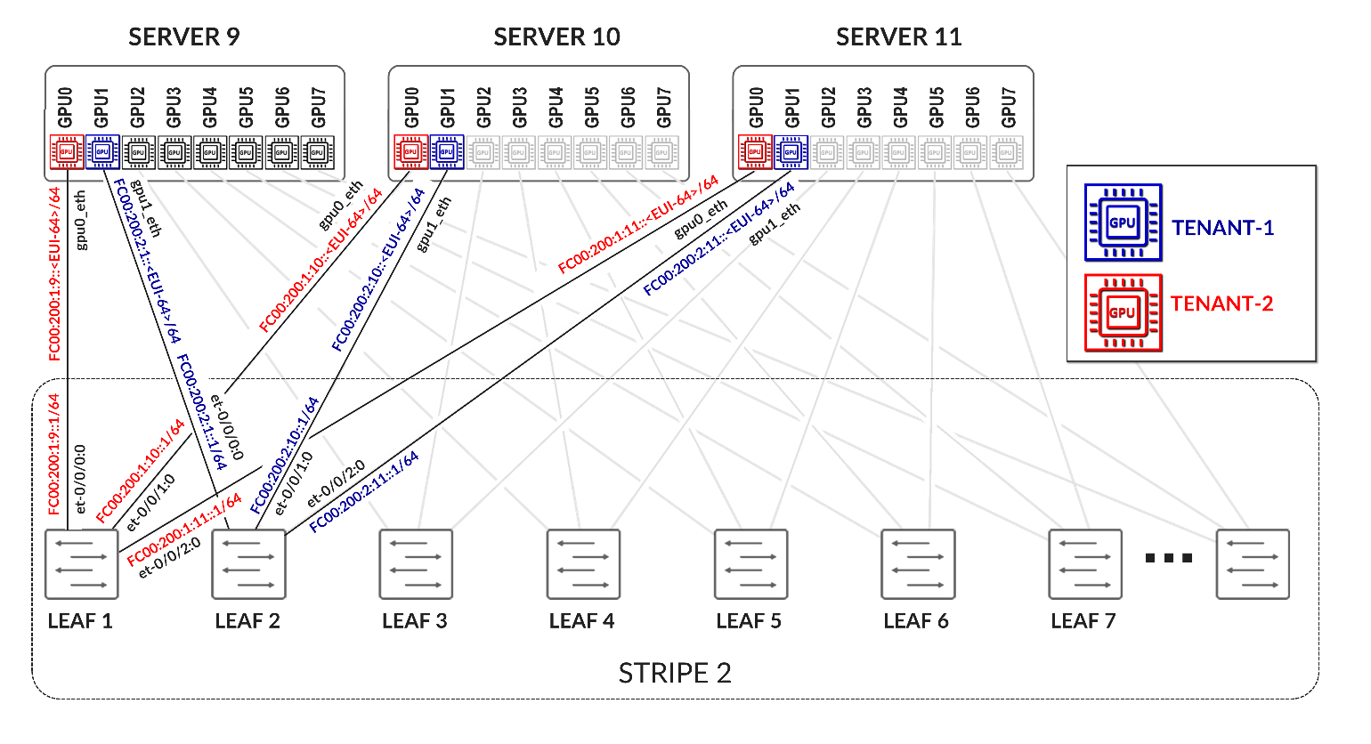
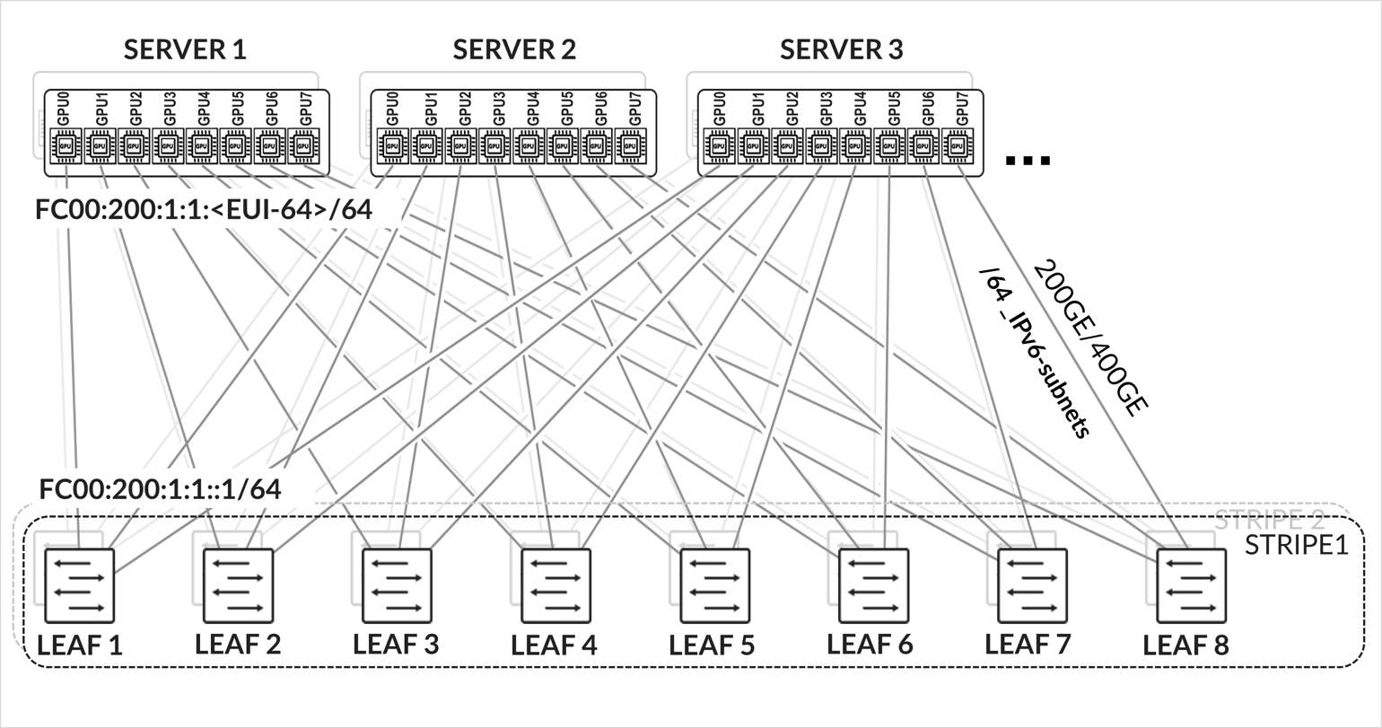
The GPU servers are connected following a rail-aligned architecture as described in the Backend GPU Rail Optimized Stripe Architecture section where GPU 0 is connected to the first Leaf node, GPU 1 is connected to the second leaf node and so on, as shown in Figure 35
Figure 35. GPU servers to leaf nodes rail-aligned connectivity
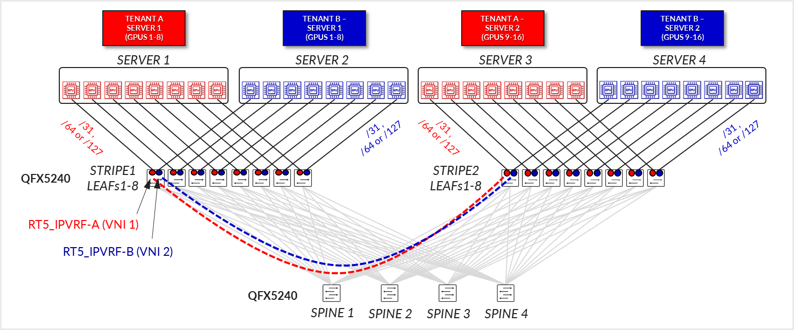
Each server to leaf node link is configured with a /31 IPv4 address as shown in Figure 35 and Table 10.
Table 10. GPU Servers to Leaf Nodes Connections.
| SUBNET | LEAF NODE INTERFACE |
LEAF NODE IPv4 ADDRESS |
GPU NIC |
GPU NIC IPv4 ADDRESS |
|---|---|---|---|---|
| /31_subnet1-1 | Stripe 1 Leaf 1 - et-0/0/0:0 | 10.200.0.0/31 | Server 1 - gpu0_eth | 10.200.0.1/31 |
| /31_subnet1-2 | Stripe 1 Leaf 2 - et-0/0/0:0 | 10.200.0.2/31 | Server 1 - gpu1_eth | 10.200.0.3/31 |
| /31_subnet1-3 | Stripe 1 Leaf 3 - et-0/0/0:0 | 10.200.0.4/31 | Server 1 - gpu2_eth | 10.200.0.5/31 |
| /31_subnet1-4 | Stripe 1 Leaf 4 - et-0/0/0:0 | 10.200.0.6/31 | Server 1 - gpu3_eth | 10.200.0.7/31 |
| /31_subnet1-5 | Stripe 1 Leaf 5 - et-0/0/0:0 | 10.200.0.8/31 | Server 1 - gpu4_eth | 10.200.0.9/31 |
| /31_subnet1-6 | Stripe 1 Leaf 6 - et-0/0/0:0 | 10.200.0.10/31 | Server 1 - gpu5_eth | 10.200.0.11/31 |
| /31_subnet1-7 | Stripe 1 Leaf 7 - et-0/0/0:0 | 10.200.0.12/31 | Server 1 - gpu6_eth | 10.200.0.13/31 |
| /31_subnet1-8 | Stripe 1 Leaf 8 - et-0/0/0:0 | 10.200.0.14/31 | Server 1 - gpu7_eth | 10.200.0.15/31 |
| /31_subnet1-9 | Stripe 1 Leaf 1 - et-0/0/1:0 | 10.200.0.16/31 | Server 2 - gpu0_eth | 10.200.0.17/31 |
| /31_subnet1-10 | Stripe 1 Leaf 2 - et-0/0/1:0 | 10.200.0.18/31 | Server 2 - gpu1_eth | 10.200.0.19/31 |
| /31_subnet1-11 | Stripe 1 Leaf 3 - et-0/0/1:0 | 10.200.0.20/31 | Server 2 - gpu2_eth | 10.200.0.21/31 |
| /31_subnet1-12 | Stripe 1 Leaf 4 - et-0/0/1:0 | 10.200.0.22/31 | Server 2 - gpu3_eth | 10.200.0.23/31 |
| /31_subnet1-13 | Stripe 1 Leaf 5 - et-0/0/1:0 | 10.200.0.24/31 | Server 2 - gpu4_eth | 10.200.0.25/31 |
| /31_subnet1-14 | Stripe 1 Leaf 6 - et-0/0/1:0 | 10.200.0.26/31 | Server 2 - gpu5_eth | 10.200.0.27/31 |
| /31_subnet1-15 | Stripe 1 Leaf 7 - et-0/0/1:0 | 10.200.0.28/31 | Server 2 - gpu6_eth | 10.200.0.29/31 |
| /31_subnet1-16 | Stripe 1 Leaf 8 - et-0/0/1:0 | 10.200.0.30/31 | Server 2 - gpu7_eth | 10.200.0.31/31 |
| /31_subnet1-17 | Stripe 1 Leaf 1 - et-0/0/2:0 | 10.200.0.32/31 | Server 3 - gpu0_eth | 10.200.0.33/31 |
| /31_subnet1-18 | Stripe 1 Leaf 2 - et-0/0/2:0 | 10.200.0.34/31 | Server 3 - gpu1_eth | 10.200.0.35/31 |
| /31_subnet1-19 | Stripe 1 Leaf 3 - et-0/0/2:0 | 10.200.0.36/31 | Server 3 - gpu2_eth | 10.200.0.37/31 |
| /31_subnet1-20 | Stripe 1 Leaf 4 - et-0/0/2:0 | 10.200.0.38/31 | Server 3 - gpu3_eth | 10.200.0.39/31 |
| /31_subnet1-21 | Stripe 1 Leaf 5 - et-0/0/2:0 | 10.200.0.40/31 | Server 3 - gpu4_eth | 10.200.0.41/31 |
| /31_subnet1-22 | Stripe 1 Leaf 6 - et-0/0/2:0 | 10.200.0.42/31 | Server 3 - gpu5_eth | 10.200.0.43/31 |
| /31_subnet1-23 | Stripe 1 Leaf 7 - et-0/0/2:0 | 10.200.0.44/31 | Server 3 - gpu6_eth | 10.200.0.45/31 |
| /31_subnet1-24 | Stripe 1 Leaf 8 - et-0/0/2:0 | 10.200.0.46/31 | Server 3 - gpu7_eth | 10.200.0.47/31 |
|
. . . |
||||
| /31_subnet2-1 | Stripe 2 Leaf 1 - et-0/0/0:0 | 10.200.1.0/31 | Server 9 - gpu0_eth | 10.200.1.1/31 |
| /31_subnet2-2 | Stripe 2 Leaf 2 - et-0/0/0:0 | 10.200.1.2/31 | Server 9 - gpu1_eth | 10.200.1.3/31 |
| /31_subnet2-3 | Stripe 2 Leaf 3 - et-0/0/0:0 | 10.200.1.4/31 | Server 9 - gpu2_eth | 10.200.1.5/31 |
| /31_subnet2-4 | Stripe 2 Leaf 4 - et-0/0/0:0 | 10.200.1.6/31 | Server 9 - gpu3_eth | 10.200.1.7/31 |
| /31_subnet2-5 | Stripe 2 Leaf 5 - et-0/0/0:0 | 10.200.1.8/31 | Server 9 - gpu4_eth | 10.200.1.9/31 |
| /31_subnet2-6 | Stripe 2 Leaf 6 - et-0/0/0:0 | 10.200.1.10/31 | Server 9 - gpu5_eth | 10.200.1.11/31 |
| /31_subnet2-7 | Stripe 2 Leaf 7 - et-0/0/0:0 | 10.200.1.12/31 | Server 9 - gpu6_eth | 10.200.1.13/31 |
|
. . . |
These interfaces are configured as untagged interfaces, with family inet and a static IPv4 address as shown in the example below:
Table 11. GPU Server to Leaf Nodes Interface Configuration Example.
The MTU is configured as per Recommended MTU section.
Follow the steps in:
AMD Configuration | Juniper Networks to configure the interfaces on AMD GPU servers or NVIDIA Configuration | Juniper Networks for NVIDIA GPU servers.
Configure the netplan as shown in the example below.
jnpr@H100-01:/etc/netplan$ sudo cat 00-installer-config-type5_vrf.yaml
# This is the network config written by 'subiquity'
network:
  version: 2
  ethernets:
    eno3:
      critical: true
      dhcp4: false
      addresses:
        - ******
      routes:
        - to: 10.161.32.0/21
          scope: link
          from: 10.161.38.81
      nameservers:
        addresses:
        - 8.8.8.8
    mgmt_eth:
      match:
        macaddress: 6c:fe:54:48:2e:48
      dhcp4: false
      addresses:
        - 10.10.1.16/31
      nameservers:
        addresses:
        - 8.8.8.8
      routes:
        - to: default
          via: 10.10.1.17
      set-name: mgmt_eth
    gpu0_eth:
      match:
        macaddress: a0:88:c2:3b:50:66
      dhcp4: false
      mtu: 9000
      addresses:
        - 10.200.0.1/31
      routes:
        - to: 10.200.0.0/16
          via: 10.200.0.0
          table: 100
        - to: 10.200.0.0/24
          via: 10.200.0.0
        - to: 10.200.8.0/24
          via: 10.200.0.0
      routing-policy:
        - from: 10.200.0.1
          table: 100
          priority: 200
      set-name: gpu0_eth
    gpu1_eth:
      match:
        macaddress: a0:88:c2:3b:50:6a
      dhcp4: false
      mtu: 9000
      addresses:
        - 10.200.0.3/31
      routes:
        - to: 10.200.0.0/16
          via: 10.200.0.2
          table: 101
        - to: 10.200.1.0/24
          via: 10.200.0.2
        - to: 10.200.9.0/24
          via: 10.200.0.2
      routing-policy:
        - from: 10.200.0.3
          table: 101
          priority: 201
      set-name: gpu1_eth
    gpu2_eth:
      match:
        macaddress: a0:88:c2:3b:50:6e
      dhcp4: false
      mtu: 9000
      addresses:
        - 10.200.0.5/31
      routes:
        - to: 10.200.0.0/16
          via: 10.200.0.4
          table: 102
        - to: 10.200.2.0/24
          via: 10.200.0.4
        - to: 10.200.10.0/24
          via: 10.200.0.4
      routing-policy:
        - from: 10.200.0.5
          table: 102
          priority: 202
      set-name: gpu2_eth
    gpu3_eth:
      match:
        macaddress: a0:88:c2:3b:50:72
      dhcp4: false
      mtu: 9000
      addresses:
        - 10.200.0.7/31
      routes:
        - to: 10.200.0.0/16
          via: 10.200.0.6
          table: 103
        - to: 10.200.3.0/24
          via: 10.200.0.6
        - to: 10.200.11.0/24
          via: 10.200.0.6
      routing-policy:
        - from: 10.200.0.7
          table: 103
          priority: 203
      set-name: gpu3_eth
    gpu4_eth:
      match:
        macaddress: a0:88:c2:0a:79:48
      dhcp4: false
      mtu: 9000
      addresses:
        - 10.200.0.9/31
      routes:
        - to: 10.200.0.0/16
          via: 10.200.0.8
          table: 104
        - to: 10.200.4.0/24
          via: 10.200.0.8
        - to: 10.200.12.0/24
          via: 10.200.0.8
      routing-policy:
        - from: 10.200.0.9
          table: 104
          priority: 204
      set-name: gpu4_eth
    gpu5_eth:
      match:
        macaddress: a0:88:c2:0a:79:4c
      dhcp4: false
      mtu: 9000
      addresses:
        - 10.200.0.11/31
      routes:
        - to: 10.200.0.0/16
          via: 10.200.0.10
          table: 105
        - to: 10.200.5.0/24
          via: 10.200.0.10
        - to: 10.200.13.0/24
          via: 10.200.0.10
      routing-policy:
        - from: 10.200.0.11
          table: 105
          priority: 205
      set-name: gpu5_eth
    gpu6_eth:
      match:
        macaddress: a0:88:c2:0a:79:40
      dhcp4: false
      mtu: 9000
      addresses:
        - 10.200.0.13/31
      routes:
        - to: 10.200.0.0/16
          via: 10.200.0.12
          table: 106
        - to: 10.200.6.0/24
          via: 10.200.0.12
        - to: 10.200.14.0/24
          via: 10.200.0.12
      routing-policy:
        - from: 10.200.0.13
          table: 106
          priority: 206
      set-name: gpu6_eth
    gpu7_eth:
      match:
        macaddress: a0:88:c2:0a:79:44
      dhcp4: false
      mtu: 9000
      addresses:
        - 10.200.0.15/31
      routes:
        - to: 10.200.0.0/16
          via: 10.200.0.14
          table: 107
        - to: 10.200.7.0/24
          via: 10.200.0.14
        - to: 10.200.15.0/24
          via: 10.200.0.14
      routing-policy:
        - from: 10.200.0.15
          table: 107
          priority: 207
      set-name: gpu7_eth
    stor0_eth:
      match:
        macaddress: b8:3f:d2:63:e5:44
      dhcp4: false
      mtu: 9000
      addresses:
        - 10.100.1.13/31
      routes:
        - to: 10.100.0.0/21
          via: 10.100.1.12
      set-name: stor0_eth
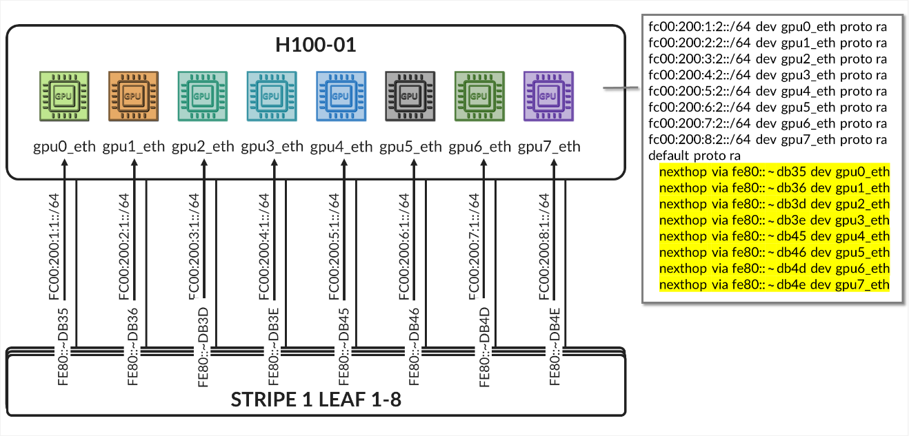
The /24 routes allow communication between the GPUs belonging to a specific tenant in different stripes:
Example:
Figure 36. Per-tenant GPU server routes example 
Table 12. Per-Tenant GPU Server Interface Connection Examples.
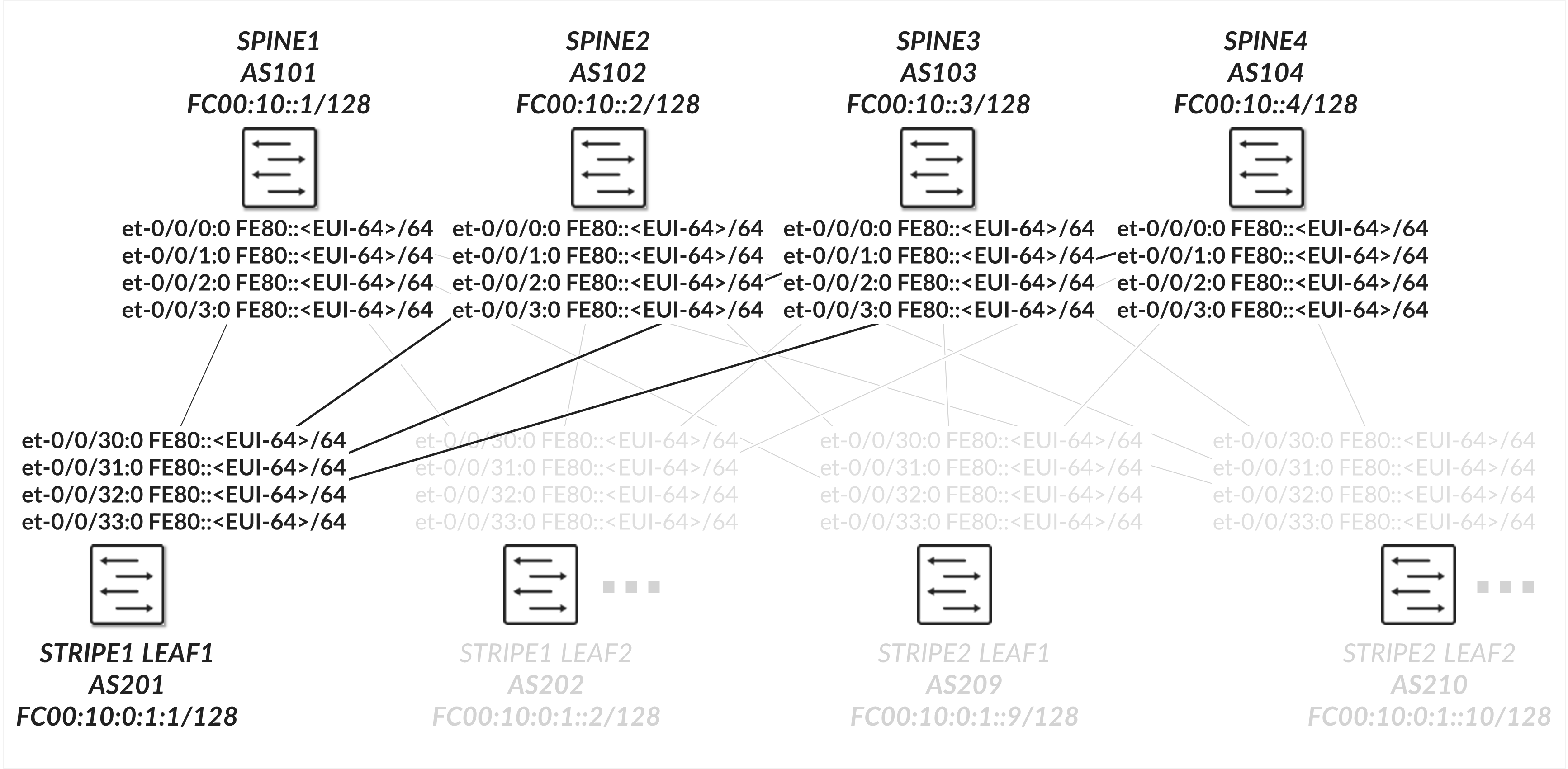
Spine nodes to leaf connections
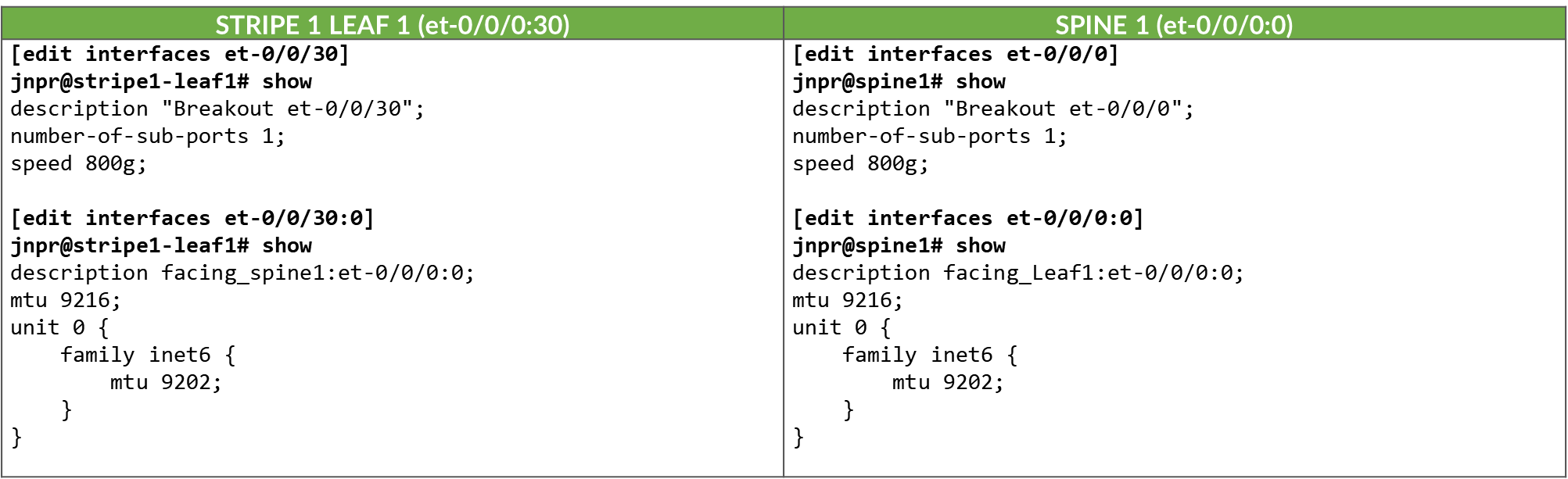
The interfaces between the leaf and spine nodes do not require explicitly configured IP addresses and are configured as untagged interfaces with only family inet and family inet6 to enable processing of IPv4 and IPv6 traffic as shown in Figure 37
Figure 37. Leaf nodes to spine nodes connectivity
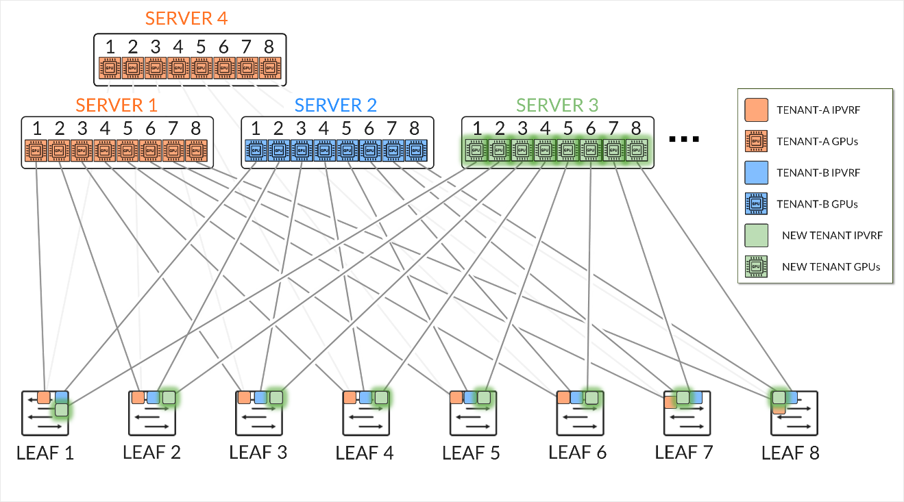
Table 13. Spine to Leaf Interface Configuration Example
Notice that enabling IPv4 on this interface is not necessary.
Enabling IPv6 on an interface automatically assigns a link-local IPv6 address. The switch autogenerate link local addresses for the interfaces using the EUI-64 address format (based on the interface’s MAC address), as shown in table 14.
Table 14. Spine and Leaf IPv6-Enabled Interface Link Local Addresses
| LEAF NODE INTERFACE | LEAF NODE IPv6 ADDRESS | SPINE NODE INTERFACE | SPINE IPv6 ADDRESS |
|---|---|---|---|
| Stripe 1 Leaf 1 - et-0/0/30:0 | fe80::9e5a:80ff:fec1:ae00/64 | Spine 1 – et-0/0/0:0 | fe80::9e5a:80ff:feef:a28f/64 |
| Stripe 1 Leaf 1 - et-0/0/31:0 | fe80::9e5a:80ff:fec1:ae08/64 | Spine 2 – et-0/0/1:0 | fe80::5a86:70ff:fe7b:ced5/64 |
| Stripe 1 Leaf 1 - et-0/0/32:0 | fe80::9e5a:80ff:fec1:af00/64 | Spine 3 – et-0/0/2:0 | fe80::5a86:70ff:fe78:e0d5/64 |
| Stripe 1 Leaf 1 - et-0/0/33:0 | fe80::9e5a:80ff:fec1:af08/64 | Spine 4 – et-0/0/3:0 | fe80::5a86:70ff:fe79:3d5/64 |
| Stripe 1 Leaf 2 - et-0/0/30:0 | fe80::5a86:70ff:fe79:dad5/64 | Spine 1 – et-0/0/0:0 | fe80::9e5a:80ff:feef:a297/64 |
| Stripe 1 Leaf 2 - et-0/0/31:0 | fe80::5a86:70ff:fe79:dadd/64 | Spine 2 – et-0/0/1:0 | fe80::5a86:70ff:fe7b:cedd/64 |
| Stripe 1 Leaf 2 - et-0/0/32:0 | fe80::5a86:70ff:fe79:dbd5/64 | Spine 3 – et-0/0/2:0 | fe80::5a86:70ff:fe78:e0dd/64 |
| Stripe 1 Leaf 2 - et-0/0/33:0 | fe80::5a86:70ff:fe79:dbdd/64 | Spine 4 – et-0/0/3:0 | fe80::5a86:70ff:fe79:3dd/64 |
|
. . . |
These addresses are advertised through standard router advertisements as part of the IPv6 Neighbor Discovery process which must be enabled on all the interfaces between the leaf and spine nodes as shown:
Table 15. IPv6 Router Advertisement on Leaf and Spine
Interfaces
To verify that router advertisements are being sent you can use show ipv6
router-advertisement interface <interface> and show ipv6
neighbors:
jnpr@stripe1-leaf1> show ipv6 router-advertisement interface et-0/0/0:0
Interface: et-0/0/0:0.0
  Advertisements sent: 4, last sent 00:02:28 ago
  Solicits sent: 1, last sent 00:08:06 ago
  Solicits received: 0
  Advertisements received: 3
  Solicited router advertisement unicast: Disable
  IPv6 RA Preference: DEFAULT/MEDIUM
  Passive mode: Disable
  Upstream mode: Disable
  Downstream mode: Disable
  Proxy blackout timer: Not Running
  Advertisement from fe80::9e5a:80ff:feef:a28f, heard 00:01:57 ago
    Managed: 0
    Other configuration: 0
    Reachable time: 0 ms
    Default lifetime: 1800 sec
    Retransmit timer: 0 ms
    Current hop limit: 64
jnpr@stripe1-leaf1> show ipv6 neighbors
IPv6 Address    Linklayer Address  State       Exp   Rtr  Secure  Interface
fe80::5a86:70ff:fe78:e0d5       58:86:70:78:e0:d5  reachable   11    yes  no      et-0/0/1:0.0
fe80::5a86:70ff:fe79:3d5        58:86:70:79:03:d5  reachable   23    yes  no      et-0/0/33:0.0
fe80::5a86:70ff:fe7b:ced5       58:86:70:7b:ce:d5  reachable   13    yes  no      et-0/0/32:0.0
fe80::9e5a:80ff:feef:a28f       9c:5a:80:ef:a2:8f  reachable   25    yes  no      et-0/0/0:0.0
Total entries: 4
All leaf and spine nodes are also configured with both IPv4 and IPv6 loopback addresses (under lo0.0).
The loopback and Autonomous System numbers for all devices in the fabric are included in table 16:
Table 16. Spine and Leaf Loopback Addresses and ASNs
| LEAF NODE INTERFACE | lo0.0 IPV6 ADDRESS | Local AS # |
|---|---|---|
| Stripe 1 Leaf 1 | 10.0.1.1/32 | 201 |
| Stripe 1 Leaf 2 | 10.0.1.2/32 | 202 |
| Stripe 1 Leaf 3 | 10.0.1.3/32 | 203 |
| Stripe 1 Leaf 4 | 10.0.1.4/32 | 204 |
| Stripe 1 Leaf 5 | 10.0.1.5/32 | 205 |
| Stripe 1 Leaf 6 | 10.0.1.6/32 | 206 |
| Stripe 1 Leaf 7 | 10.0.1.7/32 | 207 |
| Stripe 1 Leaf 8 | 10.0.1.8/32 | 208 |
| Stripe 2 Leaf 1 | 10.0.1.9/32 | 209 |
| Stripe 2 Leaf 2 | 10.0.1.10/32 | 210 |
|
. . . |
||
| SPINE1 | 10.0.0.1/32 | 101 |
| SPINE2 | 10.0.0.2/32 | 102 |
| SPINE3 | 10.0.0.3/32 | 103 |
| SPINE4 | 10.0.0.4/32 | 104 |
Table 17. Spine and Leaf Loopback Address Configuration Example
Recommended MTU
Configure the MTU consistently across the fabric and make sure that the MTU of the server->leaf links does not exceed the MTU of the leaf->spine links considering the extra overhead of the VXLAN encapsulation.
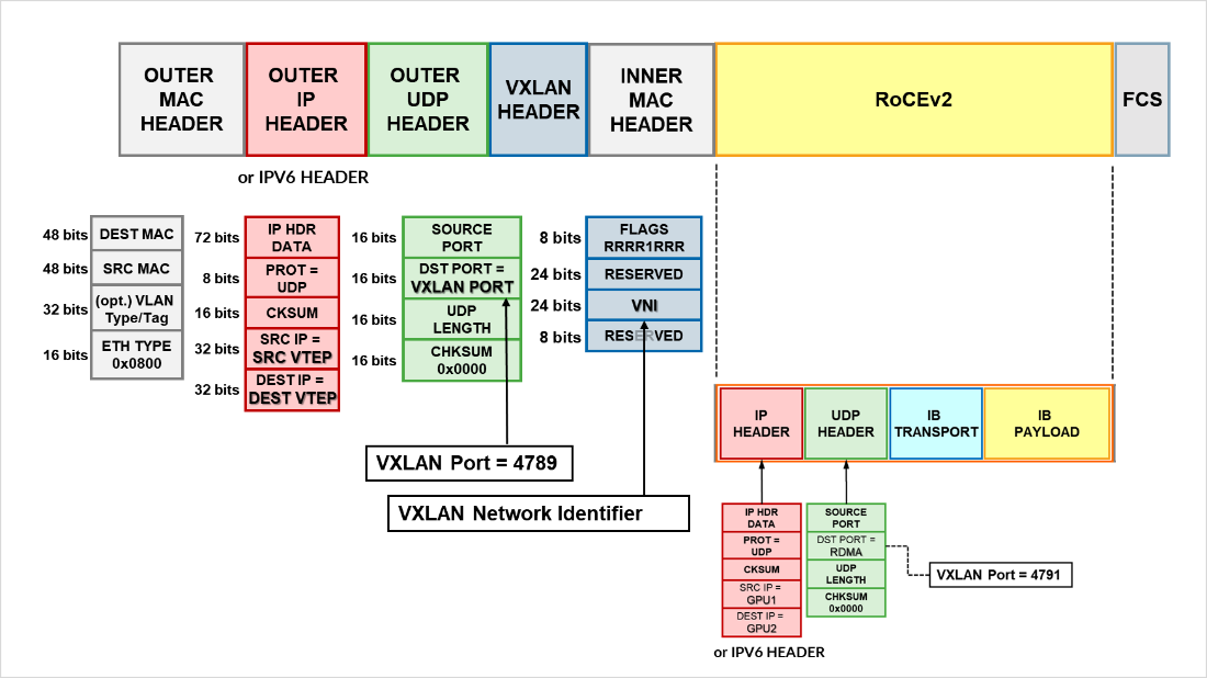
VXLAN Overhead Calculation
Table 18. VXLAN Overhead Calculation
| HEADER | BYTES |
|---|---|
| Outer Ethernet | 14 |
| Outer IP (IPv4) | 20 |
| UDP | 8 |
| VXLAN | 8 |
| Total | 50 bytes |
If, for example, the MTU of the physical interface on the leaf->spine links is configured as 9216 bytes, the value of the MTU on the logical interface should be set to at least 9166 bytes.
9216 bytes (physical interface MTU) - 50 (Total Overhead) = 9166 usable → round to 9160 MTU on logical interface is ideal.
This guarantees that when a server sends a 9000-byte payload:
- The leaf adds ~50 bytes of VXLAN encapsulation
- The resulting ~9050-byte packet fits in the 9216-byte MTU across the fabric
For IPv6, the MTU can also be calculated as:
VXLAN Overhead Calculation
| HEADER | BYTES |
|---|---|
| Outer Ethernet | 14 |
| Outer IP (IPv4) | 40 |
| UDP | 8 |
| VXLAN | 8 |
| Total | 70 bytes |
Recommended MTU Strategy
Table 19. Recommended MTU
| LINK TYPE | MTU |
|---|---|
| Server ↔ Leaf | 9000 |
| Leaf ↔ Spine IPv4 | 9160 |
| Leaf ↔ Spine IPv6 | 9140 |
It is important to keep in mind that RoCEv2 message sizes are still limited by the RDMA MTU reported by ibv_devinfo.
jnpr@MI300-01:~/SCRIPTS$ ibv_devinfo -d bnxt_re0
hca_id: bnxt_re0
        transport:              InfiniBand (0)
        fw_ver:                 230.2.49.0
        node_guid:      7ec2:55ff:febd:75d0
        sys_image_guid:         7ec2:55ff:febd:75d0
        vendor_id:              0x14e4
        vendor_part_id:         5984
        hw_ver:                 0x1D42
        phys_port_cnt:          1
                port:   1
                        state:          PORT_ACTIVE (4)
                         max_mtu:               4096 (5)
                         active_mtu:            4096 (5)
                        sm_lid:                 0
                        port_lid:                       0
                        port_lmc:               0x00
                        link_layer:                     Ethernet
Table 20. MTU Types: Ownership and Functional Role
| MTU TYPE | OWNER | PURPOSE |
|---|---|---|
|
Interface MTU (e.g. 9000) ifconfig, ip |
Linux network stack | Defines the max L3/IP packet size |
|
RDMA MTU (e.g. 4096) ibv_devinfo |
RDMA stack | Defines the max RDMA message size per Work Queue Element (WQE) |
The RDMA MTU can be configured at the verbs level, and it’s negotiated during QP (Queue Pair) setup. You cannot override it by just setting the NIC's MTU to a higher value, but you would need to use low-level tools or RDMA apps.
Some performance tools such as ib_send_bw, ib_write_bw (via -m flag). For example:
ib_write_bw -m 1024 # sets RDMA MTU to 1024 bytes
ib_write_bw -m 4096 # sets RDMA MTU to 4096 (max allowed according to the output of ibv_devinfo shown before)RDMA MTU must be ≤ Interface MTU – encapsulation overhead
GPU Backend Fabric Underlay
Ref. Configure BGP Unnumbered EVPN Fabric | Juniper Networks
The underlay EBGP sessions are configured between the leaf and spine nodes to use peer auto-discovery, and are configured to advertise these loopback interfaces, as shown in the example between Stripe1 Leaf 1 and Spine 1 below:
Table 21. GPU Backend Fabric: BGP Underlay with Peer Auto-Discovery – Configuration Examples
To configure peer auto discovery, the dynamic-neighbor block named underlay-dynamic-neighbors under the BGP group l3clos-inet6-auto-underlay specifies the interfaces where auto discovery is permitted. This replaces the neighbor a.b.c.d commands that would statically configure the neighbors.
The family inet6 ipv6-nd statement enables the use of IPv6 Neighbor Discovery to dynamically determine the addresses of neighbors with which to establish BGP sessions. To control and secure dynamic peer formation, a peer-as-list (discovered-as-list) is configured, restricting peering to neighbors whose autonomous system numbers fall within the defined range of AS 101–104.
The family inet unicast and family inet6 unicast statements configure the sessions to advertise both IPv4 and IPv6 prefixes. When BGP sessions are established over IPv6 link-local addresses but carry IPv4 routes, the extended-nexthop statement must be configured under family inet unicast. This allows IPv4 next-hops to be resolved across an IPv6 transport session, enabling correct installation of IPv4 prefixes in the routing table. Failing to include the extended-nexthop will result in hidden routes, as the protocol next-hop cannot be resolved.
Example:
jnpr@stripe1-leaf1> show route table inet.0 hidden 10.0.0.4/32 extensive | match "et-0/0/0|reason"
Source: fe80::9e5a:80ff:feef:a28f%et-0/0/0:0.0
Next hop: via et-0/0/2:0.0, selected
Hidden reason: Protocol nexthop is not on the interface
The BGP sessions are also configured with multipath multiple-as, allowing multiple paths (even with different AS paths) to be considered for ECMP (Equal-Cost Multi-Path) routing. BFD (Bidirectional Forwarding Detection) is additionally enabled to accelerate convergence in case of link or neighbor failures.
You can check that the sessions have been established by using the show bgp
summary command:
jnpr@stripe1-leaf1> show bgp summary
fe80::5a86:70ff:fe78:e0d5%et-0/0/1:0.0          102         57         50       0       1       21:21   Establ
  inet.0: 4/4/4/0
  inet6.0: 0/0/0/0
fe80::5a86:70ff:fe79:3d5%et-0/0/33:0.0  104         56         50       0       1       21:21   Establ
  inet.0: 4/4/4/0
  inet6.0: 0/0/0/0
fe80::5a86:70ff:fe7b:ced5%et-0/0/32:0.0         103         56         50       0       1       21:21   Establ
  inet.0: 4/4/4/0
  inet6.0: 0/0/0/0
fe80::9e5a:80ff:feef:a28f%et-0/0/0:0.0          101         24         18       0       2        6:55   Establ
  inet.0: 4/4/4/0
  inet6.0: 0/0/0/0
Notice that when BGP sessions are established using link-local addresses Junos displays
the neighbor address along with the interface scope (e.g.
fe80::5a86:70ff:fe78:e0d5%et-0/0/1:0.0). The scope identifier (the part after the
%) is necessary because the same link-local address (fe80::/10) could exist on multiple
interfaces. The device must know which interface to use to send packets to that
neighbor. Thus, after peer discovery is completed, the show bgp summary output lists the
neighbor using the format: IPv6 link-local address % interface-name.
You can check details about the discovered neighbors using show bgp neighbor
auto-discovered as shown in the example below:
jnpr@stripe1-leaf1> show bgp neighbor auto-discovered
Peer: fe80::5a86:70ff:fe78:e0d5%et-0/0/1:0.0+49288 AS 102 Local: fe80::9e5a:80ff:fec1:ae08%et-0/0/1:0.0+179 AS 201
  Group: l3clos-inet6-auto-underlay Routing-Instance: master
  Forwarding routing-instance: master
  Type: External    State: Established    Flags: <Sync PeerAsList AutoDiscoveredNdp>
  Last State: OpenConfirm   Last Event: RecvKeepAlive
  Last Error: None
  Export: [ (LEAF_TO_SPINE_FABRIC_OUT && BGP-AOS-Policy) ]
  Options: <GracefulRestart AddressFamily Multipath LocalAS Refresh>
  Options: <MultipathAs>
  Options: <GracefulShutdownRcv>
  Address families configured: inet-unicast inet6-unicast
  Holdtime: 90 Preference: 170
  Graceful Shutdown Receiver local-preference: 0
  Local AS: 201 Local System AS: 201
  Number of flaps: 0
  Receive eBGP Origin Validation community: Reject
  Peer ID: 10.0.0.2        Local ID: 10.0.1.1          Active Holdtime: 90
  Keepalive Interval: 30         Group index: 1    Peer index: 3    SNMP index: 21
  I/O Session Thread: bgpio-0 State: Enabled
  BFD: disabled, down
  Local Interface: et-0/0/1:0.0
  NLRI for restart configured on peer: inet-unicast inet6-unicast
  NLRI advertised by peer: inet-unicast inet6-unicast
  NLRI for this session: inet-unicast inet6-unicast
  Peer supports Refresh capability (2)
  Restart time configured on the peer: 120
  Stale routes from peer are kept for: 300
  Restart time requested by this peer: 120
  Restart flag received from the peer: Notification
  NLRI that peer supports restart for: inet-unicast inet6-unicast
  NLRI peer can save forwarding state: inet-unicast inet6-unicast
  NLRI that peer saved forwarding for: inet-unicast inet6-unicast
  NLRI that restart is negotiated for: inet-unicast inet6-unicast
  NLRI of received end-of-rib markers: inet-unicast inet6-unicast
  NLRI of all end-of-rib markers sent: inet-unicast inet6-unicast
  Peer does not support LLGR Restarter functionality
  Peer supports 4 byte AS extension (peer-as 102)
  Peer does not support Addpath
  NLRI that we support extended nexthop encoding for: inet-unicast
  NLRI that peer supports extended nexthop encoding for: inet-unicast
  Table inet.0 Bit: 20000
    RIB State: BGP restart is complete
    Send state: in sync
    Active prefixes:              4
    Received prefixes:            4
    Accepted prefixes:            4
    Suppressed due to damping:    0
    Advertised prefixes:          1
  Table inet6.0 Bit: 30000
    RIB State: BGP restart is complete
    Send state: in sync
    Active prefixes:              0
    Received prefixes:            0
    Accepted prefixes:            0
    Suppressed due to damping:    0
    Advertised prefixes:          0
  Last traffic (seconds): Received 14   Sent 14   Checked 15
  Input messages:  Total 8      Updates 6       Refreshes 0     Octets 580
  Output messages: Total 4      Updates 1       Refreshes 0     Octets 172
  Output Queue[1]: 0            (inet.0, inet-unicast)
  Output Queue[2]: 0            (inet6.0, inet6-unicast)
To control the propagation of routes, and make sure the loopback interface addresses are advertised, export policies are applied to these EBGP sessions as shown in the example in table 22.
Table 22. Export policy example to advertise IPv4 routes over IPv6 Underlay with auto discovery
These policies ensure loopback reachability is advertised cleanly and without the risk of route loops.
On the spine nodes, routes are exported only if they are accepted by both the SPINE_TO_LEAF_FABRIC_OUT and BGP-AOS-Policy export policies.
- The SPINE_TO_LEAF_FABRIC_OUT policy has no match conditions and accepts all routes unconditionally, tagging them with the FROM_SPINE_FABRIC_TIER community (0:15).
- The BGP-AOS-Policy accepts BGP-learned routes as well as any routes accepted by the nested AllPodNetworks policy.
- The AllPodNetworks policy, in turn, matches directly connected IPV6 routes and tags them with the DEFAULT_DIRECT_V4 community (1:20007 and 21001:26000 on Spine1).
As a result, each spine advertises both its directly connected routes (including its loopback interface) and any routes it has received from other leaf nodes.
Example:
jnpr@spine1> show route advertising-protocol bgp fe80::9e5a:80ff:fec1:ae00%et-0/0/0:0.0
inet.0: 13 destinations, 13 routes (13 active, 0 holddown, 0 hidden)
Restart Complete
  Prefix                Nexthop         MED     Lclpref AS path
* 10.0.0.1/32   Self                            I
* 10.0.1.2/32   Self                            202 I
* 10.0.1.9/32   Self                            209 I
* 10.0.1.10/32  Self                            210 I
On the leaf nodes, routes are exported only if they are accepted by both the LEAF_TO_SPINE_FABRIC_OUT and BGP-AOS-Policy export policies.
- The LEAF_TO_SPINE_FABRIC_OUT policy accepts all routes except those learned via BGP that are tagged with the FROM_SPINE_FABRIC_TIER community (0:15). These routes are explicitly rejected to prevent re-advertisement of spine-learned routes back into the spine layer. As described earlier, spine nodes tag all routes they advertise to leaf nodes with this community to facilitate this filtering logic.
- The BGP-AOS-Policy accepts all routes allowed by the nested AllPodNetworks policy, which matches directly connected IPV6 routes and tags them with the DEFAULT_DIRECT_V4 community (5:20007 and 21001:26000 for Stripe1-Leaf1).
-
As a result, leaf nodes will advertise only their directly connected interface routes—including their loopback interfaces—to the spines.
jnpr@stripe1-leaf1> show route advertising-protocol bgp fe80::5a86:70ff:fe78:e0d5%et-0/0/1:0.0
inet.0: 7 destinations, 13 routes (7 active, 0 holddown, 0 hidden)
Restart Complete
  Prefix        Nexthop         MED     Lclpref AS path
* 10.0.1.1/32   Self                                    I
jnpr@stripe1-leaf2> show route advertising-protocol bgp fe80::9e5a:80ff:feef:a297%et-0/0/0:0.0
inet.0: 7 destinations, 13 routes (7 active, 0 holddown, 0 hidden)
Restart Complete
  Prefix        Nexthop         MED     Lclpref AS path
* 10.0.1.2/32   Self                    I
GPU Backend Fabric Overlay using IPv4
The overlay EBGP sessions are configured between the leaf and spine nodes using the IPv4 addresses of the loopback interfaces, as shown in the example between Stripe1 Leaf 1/Stripe 2 Leaf 1 and Spine 1.
Table 23. GPU Backend Fabric Overlay Using IPv4 Loopback Addresses – Stripe 1 Example
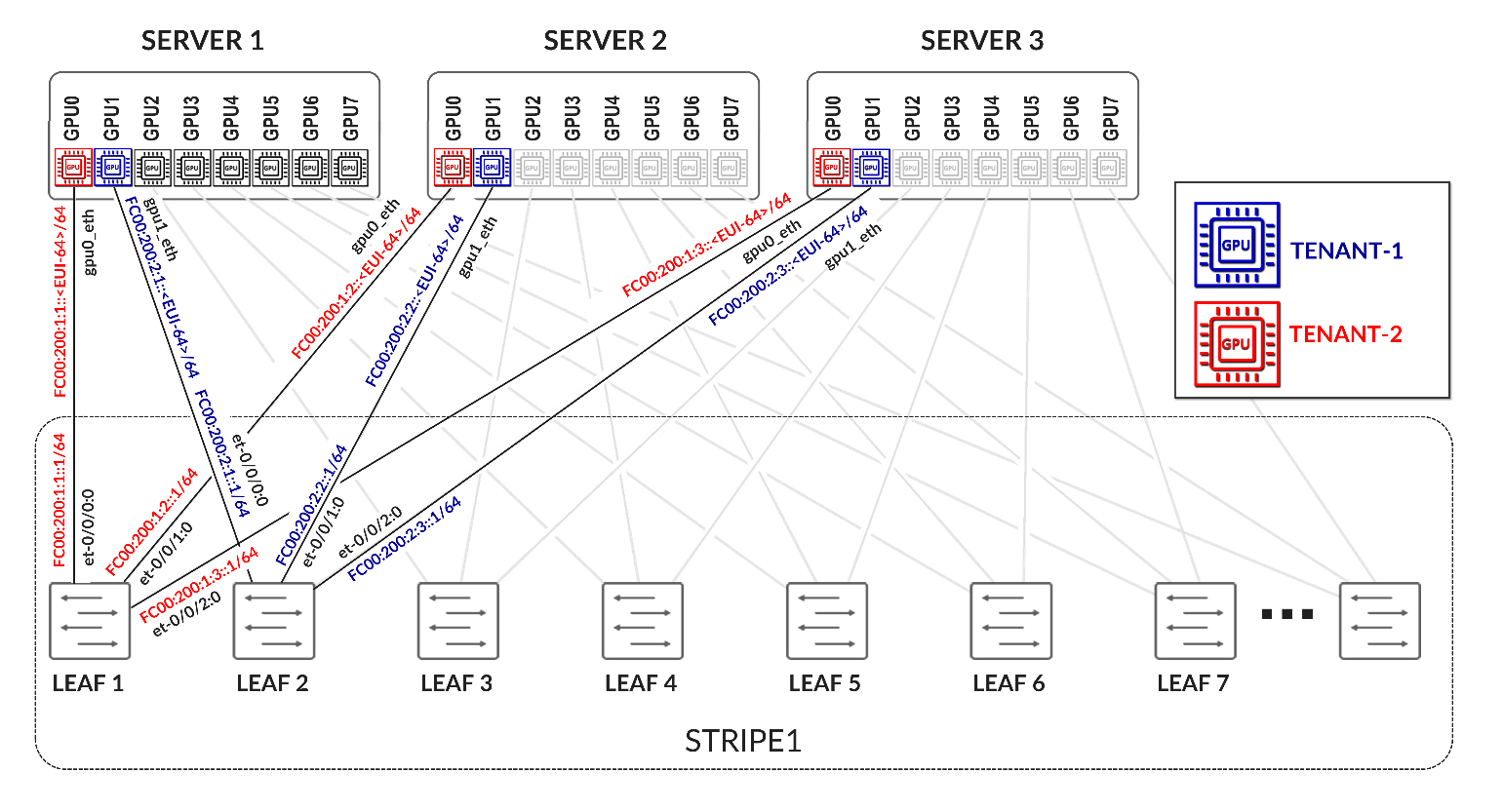
Table 24. GPU Backend Fabric Overlay Using IPv4 Loopback Addresses – Stripe 2 Example
The overlay BGP sessions use family evpn signaling to enable EVPN route exchange. The multihop ttl 1 statement allows EBGP sessions to be established between the loopback interfaces.
As with the underlay BGP sessions, these sessions are configured with multipath multiple-as, allowing multiple EVPN paths with different AS paths to be considered for ECMP (Equal-Cost Multi-Path) routing. BFD (Bidirectional Forwarding Detection) is also enabled to improve convergence time in case of failures.
The no-nexthop-change knob on the spine nodes is used to preserve the original next-hop address, which is critical in EVPN for ensuring that the remote VTEP can be reached directly. The vpn-apply-export statement is included to ensure that the export policies are evaluated for VPN address families, such as EVPN, allowing fine-grained control over which routes are advertised to each peer.
To control the propagation of routes, export policies are applied to these EBGP sessions as shown in the example in table 25.
Table 25. Export Policy example to advertise EVPN routes over IPv4 overlay
These policies are simpler in structure and are intended to enable end-to-end EVPN reachability between tenant GPUs, while preventing route loops within the overlay.
Routes will only be advertised if EVPN routing-instances have been created. Example:
Table 26. EVPN Routing-Instances for a single tenant example
across different leaf nodes.
On the spine nodes, routes are exported if they are accepted by the SPINE_TO_LEAF_EVPN_OUT policy.
The SPINE_TO_LEAF_EVPN_OUT policy has no match conditions and accepts all routes. It tags each exported route with the FROM_SPINE_EVPN_TIER community (0:14).
As a result, the spine nodes export EVPN routes received from one leaf to all other leaf nodes, allowing tenant-to-tenant communication across the fabric.
Example:
jnpr@spine1> show route advertising-protocol bgp 10.0.1.1 | match 5:10.*2001.*31
  5:10.0.1.2:2001::0::10.200.0.2::31/248
  5:10.0.1.2:2001::0::10.200.0.34::31/248
  5:10.0.1.9:2001::0::10.200.1.0::31/248
  5:10.0.1.9:2001::0::10.200.1.32::31/248
  5:10.0.1.10:2001::0::10.200.1.2::31/248
  5:10.0.1.10:2001::0::10.200.1.34::31/248
jnpr@spine1>show route advertising-protocol bgp 10.0.1.1 match-prefix 5:10.0.1.9:2001::0::10.200.1.0::31/248
bgp.evpn.0: 378 destinations, 378 routes (378 active, 0 holddown, 0 hidden)
Restart Complete
  Prefix                                        Nexthop              MED     Lclpref            AS path
  5:10.0.1.9:2001::0::10.200.1.0::31/248        * 10.0.1.9                              209 I
On the leaf nodes, routes are exported if they are accepted by both the LEAF_TO_SPINE_EVPN_OUT and EVPN_EXPORT policies.
The LEAF_TO_SPINE_EVPN_OUT policy rejects any BGP-learned routes that carry the FROM_SPINE_EVPN_TIER community (0:14). These routes are explicitly rejected to prevent re-advertisement of spine-learned routes back into the spine layer. As described earlier, spine nodes tag all routes they advertise to leaf nodes with this community to facilitate this filtering logic.
The EVPN_EXPORT policy accepts all routes without additional conditions.
As a result, the leaf nodes export only locally originated EVPN routes for the directly connected interfaces between GPU servers and the leaf nodes. These routes are part of the tenant routing instances and are required to establish reachability between GPUs belonging to the same tenant.
jnpr@stripe1-leaf1> show route advertising-protocol bgp 10.0.0.1 table Tenant-A
Tenant-A.evpn.0: 8 destinations, 20 routes (8 active, 0 holddown, 0 hidden)
Restart Complete
  Prefix                        Nexthop         MED     Lclpref         AS path
  5:10.0.1.1:2001::0::10.200.0.0::31/248
*                               Self                    I
  5:10.0.1.1:2001::0::10.200.0.16::31/248
*                               Self                    I
jnpr@stripe1-leaf1> show route advertising-protocol bgp 10.0.0.1 table Tenant-B
Tenant-B.evpn.0: 8 destinations, 20 routes (8 active, 0 holddown, 0 hidden)
Restart Complete
  Prefix                        Nexthop MED     Lclpref    AS path
  5:10.0.1.1:2002::0::10.200.0.2::31/248
*                               Self                    I
  5:10.0.1.1:2002::0::10.200.0.18::31/248
*                               Self                    I
Configuration and verification example
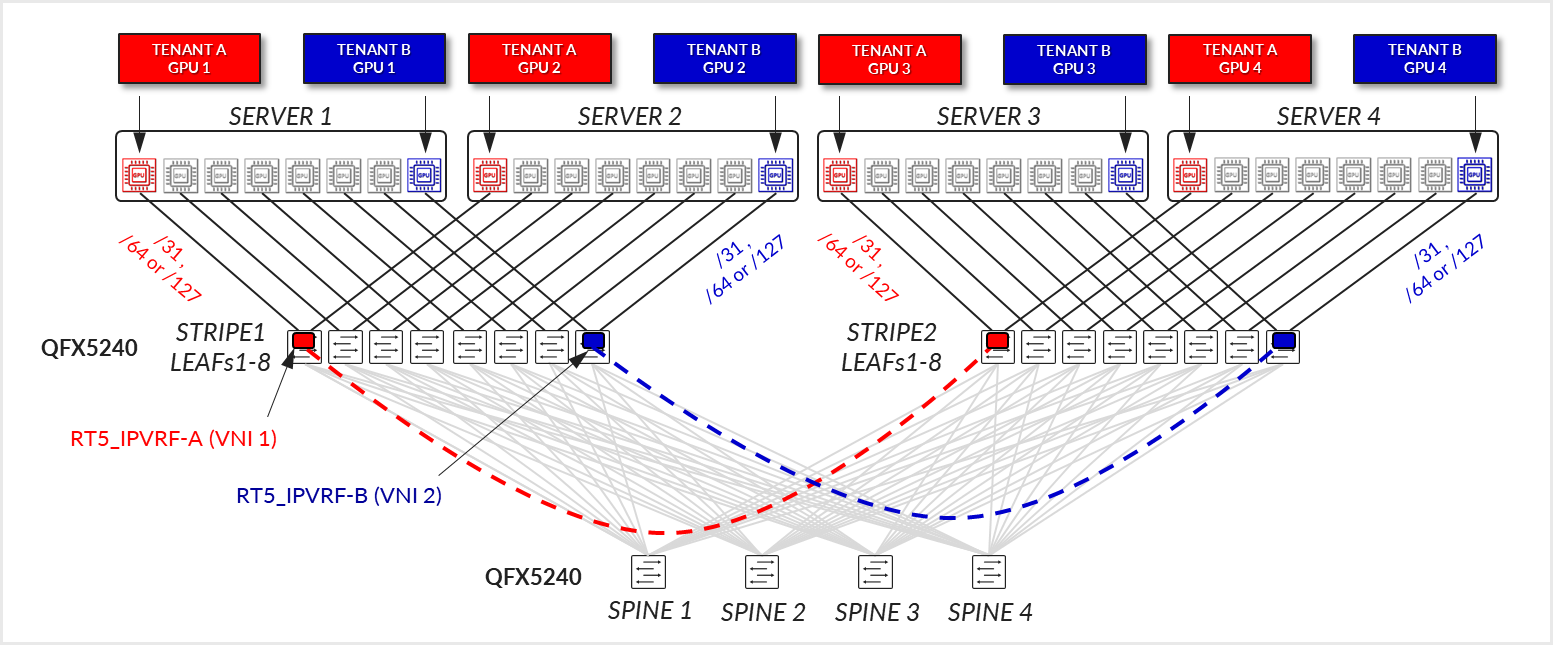
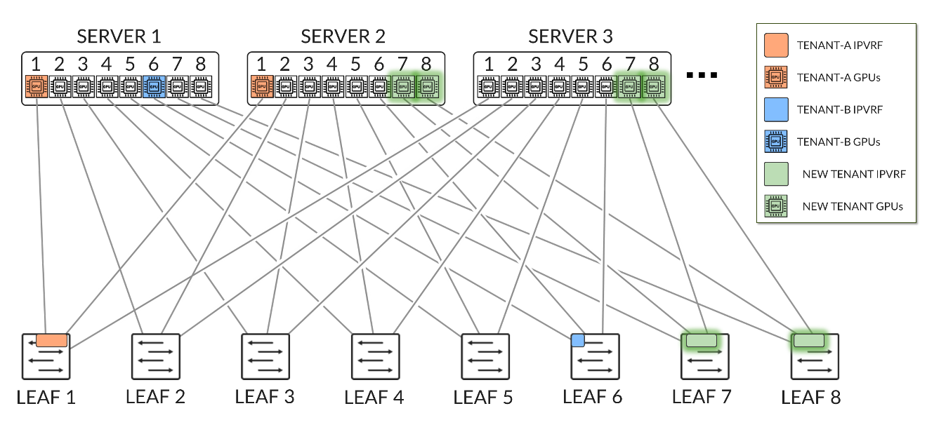
Consider the following scenario where Tenant-A has been assigned GPU 0 on Server 1 and GPU1 on Server 2, and Tenant-B has been assigned GPU 0 on Server 2 and GPU1 on Server 1 as shown in diagram 39
Figure 39. Overlay example with two tenants
Both Stripe 1 Leaf 1 and Leaf 2 have been configured for Tenant-A and Tenant-B as shown below:
Table 27. EVPN Routing-Instance for Tenant-A and Tenant-B Across Stripe 1 and Stripe 2
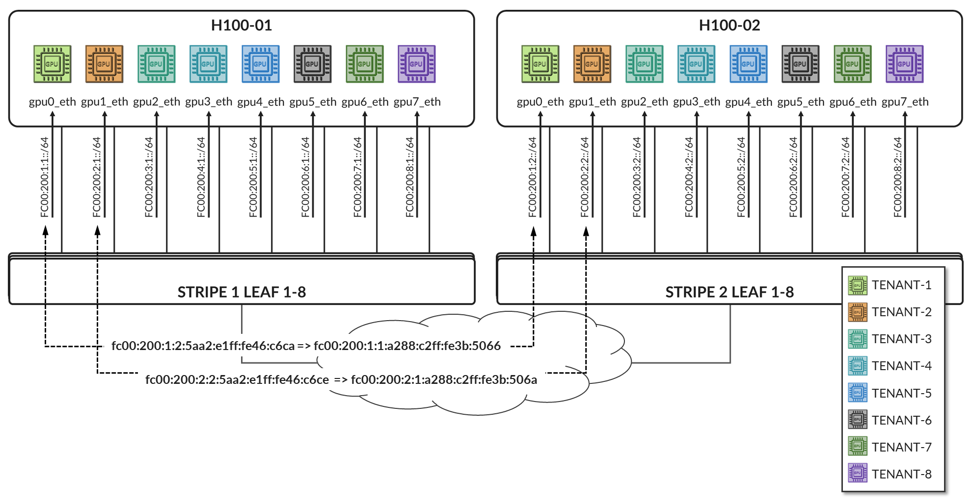
Table 28. Policies Examples for Tenant-A and Tenant-B Across Stripe 1 and Stripe 2
The routing instances create separate routing spaces for the two tenants, providing full route and traffic isolation across the EVPN-VXLAN fabric. Each routing instance has been configured with the following key elements:
- Interfaces: The interfaces listed under each tenant VRF (e.g. et-0/0/0:0.0 and et-0/0/1:0.0) are explicitly added to the corresponding routing table. By placing these interfaces under the VRF, all routing decisions and traffic forwarding associated with them are isolated from other tenants and from the global routing table. Assigning an interface that connects a particular GPU to the leaf node effectively maps that GPU to a specific tenant, isolating it from GPUs assigned to other tenants.
-
Route-distinguisher (RD):
10.0.1.1:2001 and 10.0.1.1:2002 uniquely identify EVPN routes from Tenant-A and Tenant-B, respectively. Even if both tenants use overlapping IP prefixes, the RD ensures their routes remain distinct in the BGP control plane. Although the GPU to leaf links use unique /32 prefixes, an RD is still required to advertise these routes over EVPN.
-
Route target (RT) community:
VRF targets 20001:1 and 20002:1 control which routes are exported from and imported into each tenant routing table. These values determine which routes are shared between VRFs that belong to the same tenant across the fabric and are essential for enabling fabric-wide tenant connectivity—for example, when a tenant has GPUs assigned to multiple servers across different stripes.
-
Protocols evpn parameters:
- The ip-prefix-routes controls how IP Prefix Routes (EVPN Type 5 routes) are advertised.
- The advertise direct-nexthop enables the leaf node to send IP prefix information using EVPN pure Type 5 routes, which includes a router MAC extended community. These routes include a Router MAC extended community, which allows the remote VTEP to resolve the next-hop MAC address without relying on Type 2 routes.
- The encapsulation vxlan indicates that the payload traffic for this tenant will be encapsulated using VXLAN. The same type of encapsulation must be used end to end.
-
The VXLAN Network Identifier (VNI) acts as the encapsulation tag for traffic sent across the EVPN-VXLAN fabric. When EVPN Type 5 (IP Prefix) routes are advertised, the associated VNI is included in the BGP update. This ensures that remote VTEPs can identify the correct VXLAN segment for returning traffic to the tenant’s VRF.
Unlike traditional use cases where a VNI maps to a single Layer 2 segment, in EVPN Type 5 the VNI represents the tenant-wide Layer 3 routing domain. All point-to-point subnets—such as the /32 links between GPU servers and the leaf—that belong to the same VRF are advertised with the same VNI.
In this configuration, VNIs 20001 and 20002 are mapped to the Tenant-A and Tenant-B VRFs, respectively. All traffic destined for interfaces in Tenant-A will be forwarded using VNI 20001, and all traffic for Tenant-B will use VNI 20002.
Notice that the same VNI for a specific tenant is configured on both Stripe1-Leaf1 and Stripe2-Leaf1.
- Export Policy Logic
EVPN Type 5 routes from Tenant-A are exported if they are accepted by the BGP-AOS-Policy-Tenant-A export policy, which references a nested policy named AllPodNetworks-Tenant-A (and the equivalent policies for Tenant-B)
- Policy BGP-AOS-Policy-Tenant-A controls which prefixes from this VRFs are allowed to be advertised into EVPN. It accepts any route that is permitted by the AllPodNetworks-Tenant-A policy and explicitly rejects all other routes.
- Policy AllPodNetworks-Tenant-A accepts directly connected IPv4 routes (family inet4, protocol direct) that are part of the Tenant-A VRF. It tags these routes with the TENANT-A_COMMUNITY_V4 (5:20007 21002:26000 ) community before accepting them. All other routes are rejected.
As a result, only the directly connected IPv4 routes from the Tenant-A (/32 links between GPU servers and the leaf) are exported as EVPN Type 5 routes.
To verify the interface assignments to the different tenants, use show
interfaces routing-instance <tenant-name> terse.
jnpr@stripe1-leaf1> show interfaces routing-instance Tenant-A terse
Interface       Admin   Link    Proto           Local                 Remote
et-0/0/0:0.0    up      up      inet            10.200.0.0/31
                        multiservice
lo0.1           up      up      inet            192.168.11.1        --> 0/0

jnpr@stripe1-leaf1> show interfaces routing-instance Tenant-B terse
Interface       Admin   Link    Proto           Local                 Remote
et-0/0/1:0.0    up      up      inet            10.200.0.16/31
                        multiservice
lo0.1           up      up      inet            192.168.11.2        --> 0/0
jnpr@stripe1-leaf2> show interfaces routing-instance Tenant-A terse
Interface       Admin   Link    Proto           Local                 Remote
et-0/0/0:0.0    up      up      inet            10.200.0.2/31
                        multiservice
lo0.1           up      up      inet            192.168.12.1        --> 0/0

jnpr@stripe1-leaf2> show interfaces routing-instance Tenant-B terse
et-0/0/1:0.0    up      up      inet            10.200.0.18/31
                        multiservice
lo0.1           up      up      inet            192.168.12.2        --> 0/0
You can also check the direct routes installed to the correspondent routing table:
jnpr@stripe1-leaf1> show route protocol direct table Tenant-A.inet.0
Tenant-A.inet.0: 14 destinations, 14 routes (14 active, 0 holddown, 0 hidden)
Restart Complete
@ = Routing Use Only, # = Forwarding Use Only
+ = Active Route, - = Last Active, * = Both
10.200.0.0/31           *[Direct/0] 02:24:29
                         >  via et-0/0/12:0.0
192.168.11.1/32         *[Direct/0] 02:16:52
                         >  via lo0.1
jnpr@stripe1-leaf1> show route protocol direct table Tenant-B.inet.0
Tenant-B.inet.0: 14 destinations, 14 routes (14 active, 0 holddown, 0 hidden)
Restart Complete
@ = Routing Use Only, # = Forwarding Use Only
+ = Active Route, - = Last Active, * = Both
10.200.0.16/31          *[Direct/0] 02:24:29
                         >  via et-0/0/12:0.0
192.168.11.1/32         *[Direct/0] 02:16:52
                         >  via lo0.2
jnpr@stripe1-leaf2> show route protocol direct table Tenant-A.inet.0
tenant-1.inet.0: 14 destinations, 14 routes (14 active, 0 holddown, 0 hidden)
Restart Complete
@ = Routing Use Only, # = Forwarding Use Only
+ = Active Route, - = Last Active, * = Both
10.200.0.2/31           *[Direct/0] 1d 17:42:33
                        >  via et-0/0/2:0.0
192.168.12.1/32         *[Direct/0] 02:16:52
                         >  via lo0.1
jnpr@stripe1-leaf2> show route protocol direct table Tenant-B.inet.0
tenant-1.inet.0: 14 destinations, 14 routes (14 active, 0 holddown, 0 hidden)
Restart Complete
@ = Routing Use Only, # = Forwarding Use Only
+ = Active Route, - = Last Active, * = Both
10.200.0.18/31          *[Direct/0] 1d 17:42:33
                        >  via et-0/0/3:0.0
192.168.12.1/32         *[Direct/0] 02:16:52
                         >  via lo0.2
To verify evpn l3 contexts including encapsulation, VNI, router MAC address use
show evpn l3-context.
Use <tenant-name> extensive for more details.
jnpr@stripe1-leaf1> show evpn l3-context
L3 context              Type    Adv             Encap   VNI/Label       Router MAC/GW intf dt4-sid                         dt6-sid                  dt46-sid
Tenant-A                                Cfg     Direct          VXLAN   20001           9c:5a:80:c1:b3:06
Tenant-B                                Cfg     Direct          VXLAN   20002           9c:5a:80:c1:b3:06
jnpr@stripe1-leaf1> show evpn l3-context
L3 context              Type    Adv             Encap   VNI/Label       Router MAC/GW intf dt4-sid                         dt6-sid                  dt46-sid
Tenant-A                                Cfg     Direct          VXLAN   20001           58:86:70:79:df:db
Tenant-B                                Cfg     Direct          VXLAN   20002           58:86:70:79:df:db
jnpr@stripe1-leaf1> show evpn l3-context Tenant-A extensive
L3 context: Tenant-A
  Type: Configured
  Advertisement mode: Direct nexthop, Router MAC: 9c:5a:80:c1:b3:06
  Encapsulation: VXLAN, VNI: 20001
  IPv4 source VTEP address: 10.0.1.1
  IP->EVPN export policy: BGP-AOS-Policy-Tenant-A
  Flags: 0xc209 <Configured IRB-MAC ROUTING RT-INSTANCE-TARGET-IMPORT-POLICY RT-INSTANCE-TARGET-EXPORT-POLCIY>
  Change flags: 0x20000 <VXLAN-VNI-Update-RTT-OPQ>
  Composite nexthop support: Disabled
  Route Distinguisher: 10.0.1.1:2001
  Reference count: 5
  EVPN Multicast Routing mode: CRB
jnpr@stripe1-leaf1> show evpn l3-context Tenant-B extensive
L3 context: Tenant-B
  Type: Configured
  Advertisement mode: Direct nexthop, Router MAC: 9c:5a:80:c1:b3:06
  Encapsulation: VXLAN, VNI: 20002
  IPv4 source VTEP address: 10.0.1.1
  IP->EVPN export policy: BGP-AOS-Policy-Tenant-B
  Flags: 0xc209 <Configured IRB-MAC ROUTING RT-INSTANCE-TARGET-IMPORT-POLICY RT-INSTANCE-TARGET-EXPORT-POLCIY>
  Change flags: 0x20000 <VXLAN-VNI-Update-RTT-OPQ>
  Composite nexthop support: Disabled
  Route Distinguisher: 10.0.1.1:2002
  Reference count: 5
  EVPN Multicast Routing mode: CRB
jnpr@stripe1-leaf2> show evpn l3-context Tenant-A extensive
L3 context: Tenant-A
  Type: Configured
  Advertisement mode: Direct nexthop, Router MAC: 58:86:70:79:df:db
  Encapsulation: VXLAN, VNI: 20001
  IPv4 source VTEP address: 10.0.1.2
  IP->EVPN export policy: BGP-AOS-Policy-Tenant-A
  Flags: 0xc209 <Configured IRB-MAC ROUTING RT-INSTANCE-TARGET-IMPORT-POLICY RT-INSTANCE-TARGET-EXPORT-POLCIY>
  Change flags: 0x20000 <VXLAN-VNI-Update-RTT-OPQ>
  Composite nexthop support: Disabled
  Route Distinguisher: 10.0.1.2:2001
  Reference count: 5
  EVPN Multicast Routing mode: CRB
jnpr@stripe1-leaf2> show evpn l3-context Tenant-A extensive
L3 context: Tenant-B
  Type: Configured
  Advertisement mode: Direct nexthop, Router MAC: 58:86:70:79:df:db
  Encapsulation: VXLAN, VNI: 20002
  IPv4 source VTEP address: 10.0.1.2
  IP->EVPN export policy: BGP-AOS-Policy-Tenant-B
  Flags: 0xc209 <Configured IRB-MAC ROUTING RT-INSTANCE-TARGET-IMPORT-POLICY RT-INSTANCE-TARGET-EXPORT-POLCIY>
  Change flags: 0x20000 <VXLAN-VNI-Update-RTT-OPQ>
  Composite nexthop support: Disabled
  Route Distinguisher: 10.0.1.2:2002
  Reference count: 5
  EVPN Multicast Routing mode: CRB
jnpr@stripe1-leaf1> show evpn ip-prefix-database
L3 context: Tenant-A
IPv4->EVPN Exported Prefixes
Prefix                                       EVPN route status
10.200.0.0/31                                Created
192.168.11.1/32                              Created
EVPN->IPv4 Imported Prefixes
Prefix                                       Etag
10.200.0.2/31                                0
  Route distinguisher    VNI/Label/SID           Router MAC         Nexthop/Overlay GW/ESI   Route-Status  Reject-Reason
  10.0.1.2:2001          20001                   58:86:70:79:df:db  10.0.1.2                  Accepted      n/a
192.168.12.1/32                              0
  Route distinguisher    VNI/Label/SID           Router MAC         Nexthop/Overlay GW/ESI   Route-Status  Reject-Reason
  10.0.1.2:2001          20001                   58:86:70:79:df:db  10.0.1.2                  Accepted      n/a
L3 context: Tenant-B
IPv4->EVPN Exported Prefixes
Prefix                                       EVPN route status
10.200.0.16/31                               Created
192.168.11.2/32                              Created
EVPN->IPv4 Imported Prefixes
Prefix                                       Etag
10.200.0.18/31                               0
  Route distinguisher    VNI/Label/SID           Router MAC         Nexthop/Overlay GW/ESI   Route-Status  Reject-Reason
  10.0.1.2:2002          20002                   58:86:70:79:df:db  10.0.1.2                  Accepted      n/a
192.168.12.2/32                              0
  Route distinguisher    VNI/Label/SID           Router MAC         Nexthop/Overlay GW/ESI   Route-Status  Reject-Reason
  10.0.1.2:2002          20002                   58:86:70:79:df:db  10.0.1.2                  Accepted      n/a
When EVPN Type 5 is used to implement L3 tenant isolation across a VXLAN fabric, multiple routing tables are instantiated on each participating leaf node. These tables are responsible for managing control-plane separation, enforcing tenant boundaries, and supporting the overlay forwarding model. Each routing instance (VRF) creates its own set of routing and forwarding tables, in addition to the global and EVPN-specific tables used for fabric-wide communication. These tables are listed in table 29.
Table 29. Routing and Forwarding Tables for EVPN Type 5
| TABLE | DESCRIPTON |
|---|---|
| bgp.evpn.0 |
Holds EVPN route information received via BGP, including Type 5 (IP Prefix) routes and other EVPN route types. This is the control plane source for EVPN-learned routes |
| :vxlan.inet.0 |
Used internally for VXLAN tunnel resolution. Maps VTEP IP addresses to physical next hops. |
| <tenant>.inet.0 |
The tenant-specific IPv4 unicast routing table. Contains directly connected and EVPN-imported Type 5 prefixes for that tenant. Used for routing data plane traffic. |
| <tenant>.evpn.0 | The tenant-specific EVPN table. |
The protocol next hop is extracted from each EVPN route, and resolved in inet.0. The EVPN route is added to the bgp.evpn.0 table. The result is placed in :vxlan.inet.0.
The route-target community value is used to determine which tenant the route belongs to, and the route is placed in tenant.evpn.0. From there, IPv4 routes are imported into tenant.inet4.0 to be used for route lookups when traffic arrives at the interfaces belonging to the VRF.
IPv4 EBGP sessions advertising evpn routes for Tenant-A and Tenant-B should be established. The routes should be installed in both the bgp.evpn.0 table and the <Tenant>.inet.0 table.
jnpr@stripe1-leaf1> show bgp summary | no-more
---more---
Peer                     AS      InPkt     OutPkt    OutQ   Flaps Last Up/Dwn State|#Active/Received/Accepted/Damped...
2001:10::1              101          5          4       0       0          18 Establ
  bgp.evpn.0: 4/4/4/0
  Tenant-A.evpn.0: 2/2/2/0
  Tenant-B.evpn.0: 2/2/2/0
2001:10::2              102          5          4       0       0          14 Establ
  bgp.evpn.0: 0/4/4/0
  Tenant-A.evpn.0: 0/2/2/0
  Tenant-B.evpn.0: 0/2/2/0
2001:10::3              103          5          4       0       0          10 Establ
  bgp.evpn.0: 0/4/4/0
  Tenant-A.evpn.0: 0/2/2/0
  Tenant-B.evpn.0: 0/2/2/0
2001:10::4              104          5          4       0       0           6 Establ
  bgp.evpn.0: 0/4/4/0
  Tenant-A.evpn.0: 0/2/2/0
  Tenant-B.evpn.0: 0/2/2/0

jnpr@stripe2-leaf1> show bgp summary | no-more
---more---
Peer                     AS      InPkt     OutPkt    OutQ   Flaps Last Up/Dwn State|#Active/Received/Accepted/Damped...
10.0.0.1                101        206        199       0       0     1:29:40 Establ
  bgp.evpn.0: 0/4/4/0
  Tenant-A.evpn.0: 0/2/2/0
  Tenant-B.evpn.0: 0/2/2/0
10.0.0.2                102        206        199       0       0     1:29:25 Establ
  bgp.evpn.0: 0/4/4/0
  Tenant-A.evpn.0: 0/2/2/0
  Tenant-B.evpn.0: 0/2/2/0
10.0.0.3                103        206        199       0       0     1:29:26 Establ
  bgp.evpn.0: 0/4/4/0
  Tenant-A.evpn.0: 0/2/2/0
  Tenant-B.evpn.0: 0/2/2/0
10.0.0.4                104        207        199       0       0     1:29:39 Establ
  bgp.evpn.0: 0/4/4/0
  Tenant-A.evpn.0: 0/2/2/0
  Tenant-B.evpn.0: 0/2/2/0
To check that evpn routes are being advertised use show route
advertising-protocol bgp <neighbor>. For a specific route use the
match-prefix option and include the entire evpn prefix as shown in the example below:
jnpr@stripe1-leaf1>  show route advertising-protocol bgp 10.0.0.1 table Tenant | match 5:10.0.1.1:2001 | match 31/248
  5:10.0.1.1:2001::0::10.200.0.0::31/248

jnpr@stripe1-leaf1>  show route advertising-protocol bgp 10.0.0.1 table Tenant | match 5:10.0.1.1:2002 | match 31/248
  5:10.0.1.1:2002::0::10.200.0.16::31/248
jnpr@stripe1-leaf2>  show route advertising-protocol bgp 10.0.0.1 table Tenant | match 5:10.0.1.2:2001 | match 31/248
  5:10.0.1.2:2001::0::10.200.0.2::31/248

jnpr@stripe1-leaf2>  show route advertising-protocol bgp 10.0.0.1 table Tenant | match 5:10.0.1.2:2002 | match 31/248
  5:10.0.1.2:2002::0::10.200.0.18::31/248
jnpr@ stripe1-leaf1> show route advertising-protocol bgp 10.0.0.1 match-prefix  5:10.0.1.1:2001::0::10.200.0.0::31/248 table Tenant-A
Tenant-A.evpn.0: 12 destinations, 54 routes (12 active, 0 holddown, 0 hidden)
Restart Complete
  Prefix                                Nexthop              MED     Lclpref    AS path
  5:10.0.1.1:2001::0::10.200.0.0::31/248        *  Self                                    I
jnpr@ stripe1-leaf1> show route advertising-protocol bgp 10.0.0.1 match-prefix  5:10.0.1.1:2002::0::10.200.0.16::31/248 table Tenant-B
Tenant-B.evpn.0: 12 destinations, 54 routes (12 active, 0 holddown, 0 hidden)
Restart Complete
  Prefix                                Nexthop              MED     Lclpref    AS path
  5:10.0.1.1:2002::0::10.200.0.16::31/248               *  Self                                    I
jnpr@stripe1-leaf2> show route advertising-protocol bgp 10.0.0.1 match-prefix  5:10.0.1.2:2001::0::10.200.0.2::31/248 table Tenant-A
Tenant-A.evpn.0: 12 destinations, 54 routes (12 active, 0 holddown, 0 hidden)
Restart Complete
  Prefix                                Nexthop              MED     Lclpref    AS path
  5:10.0.1.2:2001::0::10.200.0.2::31/248                *  Self                                    I
jnpr@stripe1-leaf2> show route advertising-protocol bgp 10.0.0.1 match-prefix  5:10.0.1.2:2002::0::10.200.0.18::31/248 table Tenant-B
Tenant-B.evpn.0: 12 destinations, 54 routes (12 active, 0 holddown, 0 hidden)
Restart Complete
  Prefix                                Nexthop              MED     Lclpref    AS path
  5:10.0.1.2:2002::0::10.200.0.18::31/248               *  Self                                    I
The /248 prefixes represent EVPN route type 5 advertising each IPv4 prefix connecting the GPU servers and leaf nodes.
For example: 5:10.0.1.2:2001::0::10.200.0.0::31/248 is an EVPN route type 5 for prefix 10.200.0.0/31 where:
Table 30. EVPN Type 5 Route Advertisement Fields Description.
| Name | Value | Description |
|---|---|---|
| Route type | 5: | Indicates the route is a Type 5 (IP Prefix) route |
| Route Distinguisher | 10.0.1.2:2001 | Uniquely identifies the routes |
| Placeholder fields | ::0:: | For MAC address and other Type 2-related fields (not used here) |
| IP Prefix | 10.200.0.4::31 | The actual prefix being advertised |
| VNI | 20001 | VNI to push for traffic to the destination |
| Advertising router | 10.0.0.1 (Spine 1) | Spine the route was received from. |
To check that evpn routes are being received use show route receive-protocol bgp
<neighbor>. For a specific route use the match-prefix option
and include the entire evpn prefix as shown in the example below:
jnpr@stripe1-leaf1> show route receive-protocol bgp 10.0.0.1 | match 5:10.0.1.2:2001 | match 31
  5:10.0.1.2:2001::0::10.200.0.2::31/248
jnpr@stripe1-leaf1> show route receive-protocol bgp 10.0.0.1 | match 5:10.0.1.2:2002 | match 31
  5:10.0.1.2:2002::0::10.200.0.18::31/248
jnpr@stripe1-leaf2> show route receive-protocol bgp 10.0.0.1 | match 5:10.0.1.1:2001 | match 31
  5:10.0.1.1:2001::0::10.200.0.0::31/248
jnpr@stripe1-leaf2> show route receive-protocol bgp 10.0.0.1 | match 5:10.0.1.1:2002 | match 31
  5:10.0.1.1:2002::0::10.200.0.16::31/248
The examples show routes received from Spine 1, but each route is received from all 4 spines nodes, which you can also confirm by entering:
jnpr@stripe1-leaf1>  show route table bgp.evpn.0 match-prefix 5:10.0.1.2:2001::0::10.200.0.2::31/248 | match BGP
bgp.evpn.0: 314 destinations, 1040 routes (314 active, 0 holddown, 0 hidden)
                   * [BGP/170] 11:31:33, localpref 100, from 10.0.0.1
                     [BGP/170] 11:31:21, localpref 100, from 10.0.0.2
                     [BGP/170] 11:31:14, localpref 100, from 10.0.0.3
                     [BGP/170] 11:31:10, localpref 100, from 10.0.0.4
jnpr@stripe1-leaf2>  show route table bgp.evpn.0 match-prefix 5:10.0.1.1:2001::0::10.200.0.0::31/248 | match BGP
bgp.evpn.0: 314 destinations, 1040 routes (314 active, 0 holddown, 0 hidden)
                   * [BGP/170] 11:31:13, localpref 100, from 10.0.0.1
                     [BGP/170] 11:31:41, localpref 100, from 10.0.0.2
                     [BGP/170] 11:31:12, localpref 100, from 10.0.0.3
                     [BGP/170] 11:31:52, localpref 100, from 10.0.0.4
Additional information for a given route can be found using the extensive keyword:
jnpr@stripe1-leaf1> show route table bgp.evpn.0 match-prefix 5:10.0.1.2:2001::0::10.200.0.2::31/248 active-path extensive
bgp.evpn.0: 314 destinations, 1040 routes (314 active, 0 holddown, 0 hidden)
Restart Complete
5:10.0.1.2:2001::0::10.200.0.2::31/248  (4 entries, 0 announced)
        *BGP    Preference: 170/-101
                Route Distinguisher: 10.0.1.2:2001
                Next hop type: Indirect, Next hop index: 0
                Address: 0x55dfb9c305fc
                Next-hop reference count: 48
                Kernel Table Id: 0
                Source: 10.0.0.1
                Protocol next hop: 10.0.1.2
                Label operation: Push 20001
                Label TTL action: prop-ttl
                Load balance label: Label 20001: None;
                Indirect next hop: 0x2 no-forward INH Session ID: 0
                Indirect next hop: INH non-key opaque: (nil) INH key opaque: (nil)
                State: <Active Ext>
                Local AS:   201 Peer AS:   101
                Age: 7:54:49    Metric2: 0
                Validation State: unverified
                Task: BGP_109.10.0.0.1
                AS path: 109 210 I
                Communities: 0:14 7:20007 21002:26000 target:20001:1 encapsulation:vxlan(0x8) router-mac:58:86:70:7b:10:db
                Import Accepted
                Route Label: 20001
                Overlay gateway address: 0.0.0.0
                ESI 00:00:00:00:00:00:00:00:00:00
                Localpref: 100
                Router ID: 10.0.0.1
                Secondary Tables: Tenant-A.evpn.0
                Thread: junos-main
                Indirect next hops: 1
                        Protocol next hop: 10.0.1.2 ResolvState: Resolved
                        Label operation: Push 20001
                        Label TTL action: prop-ttl
                        Load balance label: Label 20001: None;
                        Indirect next hop: 0x2 no-forward INH Session ID: 0
                        Indirect next hop: INH non-key opaque: (nil) INH key opaque: (nil)
                        Indirect path forwarding next hops: 4
                                Next hop type: Router
                                Next hop: fe80::5a86:70ff:fe7b:ced5 via et-0/0/0:0.0
                                Session Id: 0
                                Next hop: fe80::5a86:70ff:fe79:3d5 via et-0/0/1:0.0
                                Session Id: 0
                                Next hop: fe80::9e5a:80ff:feef:a28f via et-0/0/2:0.0
                                Session Id: 0
                                Next hop: fe80::5a86:70ff:fe78:e0d5 via et-0/0/3:0.0
                                Session Id: 0
                                10.0.1.2/32 Originating RIB: inet.0
                                  Node path count: 1
                                  Forwarding nexthops: 4
                                        Next hop type: Router
                                        Next hop: fe80::5a86:70ff:fe7b:ced5 via et-0/0/0:0.0
                                        Session Id: 0
                                        Next hop: fe80::5a86:70ff:fe79:3d5 via et-0/0/1:0.0
                                        Session Id: 0
                                        Next hop: fe80::9e5a:80ff:feef:a28f via et-0/0/2:0.0
                                        Session Id: 0
                                        Next hop: fe80::5a86:70ff:fe78:e0d5 via et-0/0/3:0.0
                                        Session Id: 0
---(more)---
Table 31. EVPN Type 5 Route Advertisement Fields descriptions - Extensive
| Name | Value | Description |
|---|---|---|
| Route type | 5: | Indicates the route is a Type 5 (IP Prefix) route |
| Route Distinguisher | 10.0.1.2:2001 | Uniquely identifies the routes |
| Placeholder fields | ::0:: | For MAC address and other Type 2-related fields (not used here) |
| IP Prefix | 10.200.105.0::24 | The actual prefix being advertised |
| VNI | 20001 | VNI to push for traffic to the destination |
| Advertising router | 10.0.0.1 | Spine the route was received from. |
| Protocol next hop | 10.0.1.2 (Stripe 1 Leaf 2) | Router that originated the EVPN route (remote VTEP) |
| Encapsulation | Type: 0x08 | standardized IANA-assigned value for VXLAN encapsulation in the EVPN Encapsulation extended community (RFC 9014). |
| Route target | target:20001:1 | Identifies the route as belonging to Tenant-A |
To check that the routes are being imported into the correspondent tenant’s routing
tables use show route table <tenant-name>.inet.0 protocol evpn, as
shown in the example below:
jnpr@stripe1-leaf1> show route table tenant-A.inet.0 protocol evpn | match /31
10.200.0.2/31   *[EVPN/170] 04:02:04
jnpr@stripe1-leaf1> show route table Tenant-B.inet.0 protocol evpn | match /31
10.200.0.18/31  *[EVPN/170] 04:02:04
jnpr@stripe1-leaf2> show route table tenant-A.inet.0 protocol evpn | match /31
10.200.0.0/31   *[EVPN/170] 04:02:04
jnpr@stripe1-leaf2> show route table Tenant-B.inet.0 protocol evpn | match /31
10.200.0.16/31  *[EVPN/170] 04:02:04
GPU Backend Fabric Overlay using IPv6
The overlay EBGP sessions are configured between the leaf and spine nodes using the IPv4 addresses of the loopback interfaces, as shown in the example between Stripe1 Leaf 1/Stripe 2 Leaf 1 and Spine 1.
Table 32. GPU Backend Fabric Overlay Using IPv6 Loopback Addresses – Stripe 1 Leaf 1 to Spine 1
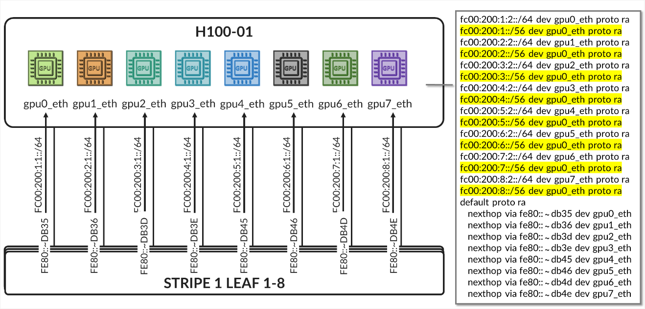
Table 33. GPU Backend Fabric Overlay Using IPv6 Loopback Addresses – Stripe 2 Leaf 1 to Spine 1
The overlay BGP sessions use family evpn signaling to enable EVPN route exchange. The
multihop ttl 1 statement allows EBGP sessions to be established between
the loopback interfaces.
As with the underlay BGP sessions, these sessions are configured with multipath
multiple-as, allowing multiple EVPN paths with different AS paths to be
considered for ECMP (Equal-Cost Multi-Path) routing. BFD (Bidirectional Forwarding
Detection) is also enabled to improve convergence time in case of failures.
The no-nexthop-change knob on the spine nodes is used to preserve the
original next-hop address, which is critical in EVPN for ensuring that the remote VTEP can
be reached directly. The vpn-apply-export is included to ensure that
the export policies are evaluated for VPN address families, such as EVPN, allowing
fine-grained control over which routes are advertised to each peer.
To control the propagation of routes, export policies are applied to these EBGP sessions as shown in the example in table 34.
Table 34. Export Policy example to advertise EVPN routes over IPv6 overlay
.png)
These policies are simpler in structure and are intended to enable end-to-end EVPN reachability between tenant GPUs, while preventing route loops within the overlay.
Routes will only be advertised if EVPN routing-instances have been created. Example:
Table 35. EVPN Routing-Instances for a single tenant example
across different leaf nodes..png)
On the spine nodes, routes are exported if they are accepted by the SPINE_TO_LEAF_EVPN_OUT policy.
- The SPINE_TO_LEAF_EVPN_OUT policy has no match conditions and accepts all routes. It tags each exported route with the FROM_SPINE_EVPN_TIER community (0:14).
As a result, the spine nodes export EVPN routes received from one leaf to all other leaf nodes, allowing tenant-to-tenant communication across the fabric.
Example:
jnpr@spine1>  show route advertising-protocol bgp 2001:10:0:1::1 | match 5:10.*2001.*31
  5:10.0.1.2:2001::0::10.200.0.2::31/248
  5:10.0.1.2:2001::0::10.200.0.34::31/248
  5:10.0.1.9:2001::0::10.200.1.0::31/248
  5:10.0.1.9:2001::0::10.200.1.32::31/248
  5:10.0.1.10:2001::0::10.200.1.2::31/248
  5:10.0.1.10:2001::0::10.200.1.34::31/248
jnpr@spine1>  show route advertising-protocol bgp 2001:10:0:1::1 match-prefix 5:10.0.1.9:2001::0::10.200.1.0::31/248
bgp.evpn.0: 378 destinations, 378 routes (378 active, 0 holddown, 0 hidden)
Restart Complete
  Prefix                                        Nexthop              MED     Lclpref            AS path
  5:10.0.1.9:2001::0::10.200.1.0::31/248        * 2001:10:0:1::9                209 I
On the leaf nodes, routes are exported if they are accepted by both the LEAF_TO_SPINE_EVPN_OUT and EVPN_EXPORT policies.
- The LEAF_TO_SPINE_EVPN_OUT policy rejects any BGP-learned routes that carry the FROM_SPINE_EVPN_TIER community (0:14). These routes are explicitly rejected to prevent re-advertisement of spine-learned routes back into the spine layer. As described earlier, spine nodes tag all routes they advertise to leaf nodes with this community to facilitate this filtering logic.
- The EVPN_EXPORT policy accepts all routes without additional conditions.
As a result, the leaf nodes export only locally originated EVPN routes for the directly connected interfaces between GPU servers and the leaf nodes. These routes are part of the tenant routing instances and are required to establish reachability between GPUs belonging to the same tenant.
jnpr@stripe1-leaf1> show route advertising-protocol bgp 2001:10::1 table Tenant-A
Tenant-A.evpn.0: 8 destinations, 20 routes (8 active, 0 holddown, 0 hidden)
Restart Complete
  Prefix                        Nexthop         MED     Lclpref         AS path
  5:10.0.1.1:2001::0::10.200.0.0::31/248
*                               Self                    I
  5:10.0.1.1:2001::0::10.200.0.16::31/248
*                               Self                    I
jnpr@stripe1-leaf1> show route advertising-protocol bgp 2001:10::1 table Tenant-B
Tenant-B.evpn.0: 8 destinations, 20 routes (8 active, 0 holddown, 0 hidden)
Restart Complete
  Prefix                        Nexthop MED     Lclpref    AS path
  5:10.0.1.1:2002::0::10.200.0.2::31/248
*                               Self                    I
  5:10.0.1.1:2002::0::10.200.0.18::31/248
*                               Self                    I
Configuration and verification example
Consider the following scenario where Tenant-A has been assigned GPU 0 on Server 1 and GPU1 on Server 2, and Tenant-B has been assigned GPU 0 on Server 2 and GPU1 on Server 1 as shown in diagram 39
Figure 39. Overlay example with two tenants
Both Stripe 1 Leaf 1 and Leaf 2 have been configured for Tenant-A and Tenant-B as shown below:
Table 36. EVPN Routing-Instance for Tenant-A and Tenant-B Across Stripe 1 and Stripe 2
.png)
Table 37. Policies Examples for Tenant-A and Tenant-B Across Stripe 1 and Stripe 2
.png)
The routing instances create separate routing spaces for the two tenants, providing full route and traffic isolation across the EVPN-VXLAN fabric. Each routing instance has been configured with the following key elements:
- Interfaces: The interfaces listed under each tenant VRF (e.g. et-0/0/0:0.0 and et-0/0/1:0.0) are explicitly added to the corresponding routing table. By placing these interfaces under the VRF, all routing decisions and traffic forwarding associated with them are isolated from other tenants and from the global routing table. Assigning an interface that connects a particular GPU to the leaf node effectively maps that GPU to a specific tenant, isolating it from GPUs assigned to other tenants.
-
Route-distinguisher (RD):
10.0.1.1:2001 and 10.0.1.1:2002 uniquely identify EVPN routes from Tenant-A and Tenant-B, respectively. Even if both tenants use overlapping IP prefixes, the RD ensures their routes remain distinct in the BGP control plane. Although the GPU to leaf links use unique /32 prefixes, an RD is still required to advertise these routes over EVPN.
-
Route target (RT) community:
VRF targets 20001:1 and 20002:1 control which routes are exported from and imported into each tenant routing table. These values determine which routes are shared between VRFs that belong to the same tenant across the fabric and are essential for enabling fabric-wide tenant connectivity—for example, when a tenant has GPUs assigned to multiple servers across different stripes.
-
Protocols evpn parameters:
- The
ip-prefix-routescontrols how IP Prefix Routes (EVPN Type 5 routes) are advertised. - The
advertise direct-nexthopenables the leaf node to send IP prefix information using EVPN pure Type 5 routes, which includes a router MAC extended community. These routes include a Router MAC extended community, which allows the remote VTEP to resolve the next-hop MAC address without relying on Type 2 routes. - The encapsulation vxlan indicates that the payload traffic for this tenant will be encapsulated using VXLAN. The same type of encapsulation must be used end to end.
-
The VXLAN Network Identifier (VNI) acts as the encapsulation tag for traffic sent across the EVPN-VXLAN fabric. When EVPN Type 5 (IP Prefix) routes are advertised, the associated VNI is included in the BGP update. This ensures that remote VTEPs can identify the correct VXLAN segment for returning traffic to the tenant’s VRF.
Unlike traditional use cases where a VNI maps to a single Layer 2 segment, in EVPN Type 5 the VNI represents the tenant-wide Layer 3 routing domain. All point-to-point subnets—such as the /32 links between GPU servers and the leaf—that belong to the same VRF are advertised with the same VNI.
In this configuration, VNIs 20001 and 20002 are mapped to the Tenant-A and Tenant-B VRFs, respectively. All traffic destined for interfaces in Tenant-A will be forwarded using VNI 20001, and all traffic for Tenant-B will use VNI 20002.
Notice that the same VNI for a specific tenant is configured on both Stripe1-Leaf1 and Stripe2-Leaf1.
- The
- Export Policy Logic
EVPN Type 5 routes from Tenant-A are exported if they are accepted by the BGP-AOS-Policy-Tenant-A export policy, which references a nested policy named AllPodNetworks-Tenant-A (and the equivalent policies for Tenant-B)
- Policy BGP-AOS-Policy-Tenant-A controls which prefixes from this VRFs are allowed to be advertised into EVPN. It accepts any route that is permitted by the AllPodNetworks-Tenant-A policy and explicitly rejects all other routes.
-
Policy AllPodNetworks-Tenant-A accepts directly connected IPv4 routes (family inet, protocol direct) that are part of the Tenant-A VRF. It tags these routes with the TENANT-A_COMMUNITY_V4 (5:20007 21002:26000 ) community before accepting them. All other routes are rejected.
As a result, only the directly connected IPv4 routes from the Tenant-A (/32 links between GPU servers and the leaf) are exported as EVPN Type 5 routes.
To verify the interface assignments to the different tenants, use: show
interfaces routing-instance <tenant-name> terse.
jnpr@stripe1-leaf1> show interfaces routing-instance Tenant-A terse
Interface       Admin   Link    Proto           Local                 Remote
et-0/0/0:0.0    up      up      inet            10.200.0.0/31
                        multiservice
lo0.1           up      up      inet            192.168.11.1        --> 0/0

jnpr@stripe1-leaf1> show interfaces routing-instance Tenant-B terse
Interface       Admin   Link    Proto           Local                 Remote
et-0/0/1:0.0    up      up      inet            10.200.0.16/31
                        multiservice
lo0.1           up      up      inet            192.168.11.2        --> 0/0
jnpr@stripe1-leaf2> show interfaces routing-instance Tenant-A terse
Interface       Admin   Link    Proto           Local                 Remote
et-0/0/0:0.0    up      up      inet            10.200.0.2/31
                        multiservice
lo0.1           up      up      inet            192.168.12.1        --> 0/0

jnpr@stripe1-leaf2> show interfaces routing-instance Tenant-B terse
et-0/0/1:0.0    up      up      inet            10.200.0.18/31
                        multiservice
lo0.1           up      up      inet            192.168.12.2        --> 0/0


You can also check the direct routes installed to the correspondent routing table:
jnpr@stripe1-leaf1> show route protocol direct table Tenant-A.inet.0
Tenant-A.inet.0: 14 destinations, 14 routes (14 active, 0 holddown, 0 hidden)
Restart Complete
@ = Routing Use Only, # = Forwarding Use Only
+ = Active Route, - = Last Active, * = Both
10.200.0.0/31           *[Direct/0] 02:24:29
                         >  via et-0/0/12:0.0
192.168.11.1/32         *[Direct/0] 02:16:52
                         >  via lo0.1
jnpr@stripe1-leaf1> show route protocol direct table Tenant-B.inet.0
Tenant-B.inet.0: 14 destinations, 14 routes (14 active, 0 holddown, 0 hidden)
Restart Complete
@ = Routing Use Only, # = Forwarding Use Only
+ = Active Route, - = Last Active, * = Both
10.200.0.16/31          *[Direct/0] 02:24:29
                         >  via et-0/0/12:0.0
192.168.11.1/32         *[Direct/0] 02:16:52
                         >  via lo0.2
jnpr@stripe1-leaf2> show route protocol direct table Tenant-A.inet.0
tenant-1.inet.0: 14 destinations, 14 routes (14 active, 0 holddown, 0 hidden)
Restart Complete
@ = Routing Use Only, # = Forwarding Use Only
+ = Active Route, - = Last Active, * = Both
10.200.0.2/31           *[Direct/0] 1d 17:42:33
                        >  via et-0/0/2:0.0
192.168.12.1/32         *[Direct/0] 02:16:52
                         >  via lo0.1
jnpr@stripe1-leaf2> show route protocol direct table Tenant-B.inet.0
tenant-1.inet.0: 14 destinations, 14 routes (14 active, 0 holddown, 0 hidden)
Restart Complete
@ = Routing Use Only, # = Forwarding Use Only
+ = Active Route, - = Last Active, * = Both
10.200.0.18/31          *[Direct/0] 1d 17:42:33
                        >  via et-0/0/3:0.0
192.168.12.1/32         *[Direct/0] 02:16:52
                         >  via lo0.2
To verify evpn l3 contexts including encapsulation, VNI, router MAC address use
show evpn l3-context.
Use <tenant-name> extensive for more details.
jnpr@stripe1-leaf1> show evpn l3-context
L3 context              Type    Adv             Encap   VNI/Label       Router MAC/GW intf dt4-sid                         dt6-sid                  dt46-sid
Tenant-A                                Cfg     Direct          VXLAN   20001           9c:5a:80:c1:b3:06
Tenant-B                                Cfg     Direct          VXLAN   20002           9c:5a:80:c1:b3:06
jnpr@stripe1-leaf1> show evpn l3-context
L3 context              Type    Adv             Encap   VNI/Label       Router MAC/GW intf dt4-sid                         dt6-sid                  dt46-sid
Tenant-A                                Cfg     Direct          VXLAN   20001           58:86:70:79:df:db
Tenant-B                                Cfg     Direct          VXLAN   20002           58:86:70:79:df:db
jnpr@stripe1-leaf1> show evpn l3-context Tenant-A extensive
L3 context: Tenant-A
  Type: Configured
  Advertisement mode: Direct nexthop, Router MAC: 9c:5a:80:c1:b3:06
  Encapsulation: VXLAN, VNI: 20001
  IPv4 source VTEP address: 2001:10:0:1::1
  IP->EVPN export policy: BGP-AOS-Policy-Tenant-A
  Flags: 0xc209 <Configured IRB-MAC ROUTING RT-INSTANCE-TARGET-IMPORT-POLICY RT-INSTANCE-TARGET-EXPORT-POLCIY>
  Change flags: 0x20000 <VXLAN-VNI-Update-RTT-OPQ>
  Composite nexthop support: Disabled
  Route Distinguisher: 10.0.1.1:2001
  Reference count: 5
  EVPN Multicast Routing mode: CRB
jnpr@stripe1-leaf1> show evpn l3-context Tenant-B extensive
L3 context: Tenant-B
  Type: Configured
  Advertisement mode: Direct nexthop, Router MAC: 9c:5a:80:c1:b3:06
  Encapsulation: VXLAN, VNI: 20002
  IPv4 source VTEP address: 2001:10:0:1::1
  IP->EVPN export policy: BGP-AOS-Policy-Tenant-B
  Flags: 0xc209 <Configured IRB-MAC ROUTING RT-INSTANCE-TARGET-IMPORT-POLICY RT-INSTANCE-TARGET-EXPORT-POLCIY>
  Change flags: 0x20000 <VXLAN-VNI-Update-RTT-OPQ>
  Composite nexthop support: Disabled
  Route Distinguisher: 10.0.1.1:2002
  Reference count: 5
  EVPN Multicast Routing mode: CRB
jnpr@stripe1-leaf2> show evpn l3-context Tenant-A extensive
L3 context: Tenant-A
  Type: Configured
  Advertisement mode: Direct nexthop, Router MAC: 58:86:70:79:df:db
  Encapsulation: VXLAN, VNI: 20001
  IPv4 source VTEP address: 2001:10:0:1::2
  IP->EVPN export policy: BGP-AOS-Policy-Tenant-A
  Flags: 0xc209 <Configured IRB-MAC ROUTING RT-INSTANCE-TARGET-IMPORT-POLICY RT-INSTANCE-TARGET-EXPORT-POLCIY>
  Change flags: 0x20000 <VXLAN-VNI-Update-RTT-OPQ>
  Composite nexthop support: Disabled
  Route Distinguisher: 10.0.1.2:2001
  Reference count: 5
  EVPN Multicast Routing mode: CRB
jnpr@stripe1-leaf2> show evpn l3-context Tenant-A extensive
L3 context: Tenant-B
  Type: Configured
  Advertisement mode: Direct nexthop, Router MAC: 58:86:70:79:df:db
  Encapsulation: VXLAN, VNI: 20002
  IPv4 source VTEP address: 2001:10:0:1::2
  IP->EVPN export policy: BGP-AOS-Policy-Tenant-B
  Flags: 0xc209 <Configured IRB-MAC ROUTING RT-INSTANCE-TARGET-IMPORT-POLICY RT-INSTANCE-TARGET-EXPORT-POLCIY>
  Change flags: 0x20000 <VXLAN-VNI-Update-RTT-OPQ>
  Composite nexthop support: Disabled
  Route Distinguisher: 10.0.1.2:2002
  Reference count: 5
  EVPN Multicast Routing mode: CRB
jnpr@stripe1-leaf1> show evpn ip-prefix-database
L3 context: Tenant-A
IPv4->EVPN Exported Prefixes
Prefix                                       EVPN route status
10.200.0.0/31                                Created
192.168.11.1/32                              Created
EVPN->IPv4 Imported Prefixes
Prefix                                       Etag
10.200.0.2/31                                0
  Route distinguisher    VNI/Label/SID           Router MAC         Nexthop/Overlay GW/ESI   Route-Status  Reject-Reason
  10.0.1.2:2001          20001                   58:86:70:79:df:db  2001:10:0:1::2      Accepted      n/a
192.168.12.1/32                              0
  Route distinguisher    VNI/Label/SID           Router MAC         Nexthop/Overlay GW/ESI   Route-Status  Reject-Reason
  10.0.1.2:2001          20001                   58:86:70:79:df:db  2001:10:0:1::2      Accepted      n/a
L3 context: Tenant-B
IPv4->EVPN Exported Prefixes
Prefix                                       EVPN route status
10.200.0.16/31                               Created
192.168.11.2/32                              Created
EVPN->IPv4 Imported Prefixes
Prefix                                       Etag
10.200.0.18/31                               0
  Route distinguisher    VNI/Label/SID           Router MAC         Nexthop/Overlay GW/ESI   Route-Status  Reject-Reason
  10.0.1.2:2002          20002                   58:86:70:79:df:db  10.0.1.2                  Accepted      n/a
192.168.12.2/32                              0
  Route distinguisher    VNI/Label/SID           Router MAC         Nexthop/Overlay GW/ESI   Route-Status  Reject-Reason
  10.0.1.2:2002          20002                   58:86:70:79:df:db  10.0.1.2                  Accepted      n/a
When EVPN Type 5 is used to implement L3 tenant isolation across a VXLAN fabric, multiple routing tables are instantiated on each participating leaf node. These tables are responsible for managing control-plane separation, enforcing tenant boundaries, and supporting the overlay forwarding model. Each routing instance (VRF) creates its own set of routing and forwarding tables, in addition to the global and EVPN-specific tables used for fabric-wide communication. These tables are listed in table 38.
Table 38. Routing and Forwarding Tables for EVPN Type 5
| TABLE | DESCRIPTON |
|---|---|
| bgp.evpn.0 |
Holds EVPN route information received via BGP, including Type 5 (IP Prefix) routes and other EVPN route types. This is the control plane source for EVPN-learned routes |
| :vxlan.inet.0 |
Used internally for VXLAN tunnel resolution. Maps VTEP IP addresses to physical next hops. |
| <tenant>.inet.0 |
The tenant-specific IPv4 unicast routing table. Contains directly connected and EVPN-imported Type 5 prefixes for that tenant. Used for routing data plane traffic. |
| <tenant>.evpn.0 | The tenant-specific EVPN table. |
The protocol next hop is extracted from each EVPN route, is extracted and resolved in inet6.0. The EVPN route is added to the bgp.evpn.0 table. The result is placed in :vxlan.inet.0.
The route-target community value is used to determine which tenant the route belongs to, and the route is placed in tenant.evpn.0. From there, IPv4 routes are imported into tenant.inet4.0 to be used for route lookups when traffic arrives at the interfaces belonging to the VRF.
IPv6 EBGP sessions advertising evpn routes for Tenant-A and Tenant-B should be established. The routes should be installed in both the bgp.evpn.0 table and the <Tenant>.inet.0 table.
jnpr@stripe1-leaf1> show bgp summary | no-more
---more---
Peer                     AS      InPkt     OutPkt    OutQ   Flaps Last Up/Dwn State|#Active/Received/Accepted/Damped...
2001:10::1                101          5          4       0       0          18 Establ
  bgp.evpn.0: 4/4/4/0
  Tenant-A.evpn.0: 2/2/2/0
               Tenant-B.evpn.0: 2/2/2/0
2001:10::2                102          5          4       0       0          14 Establ
  bgp.evpn.0: 0/4/4/0
  Tenant-A.evpn.0: 0/2/2/0
  Tenant-B.evpn.0: 0/2/2/0
2001:10::3                103          5          4       0       0          10 Establ
  bgp.evpn.0: 0/4/4/0
  Tenant-A.evpn.0: 0/2/2/0
  Tenant-B.evpn.0: 0/2/2/0
2001:10::4                104          5          4       0       0           6 Establ
  bgp.evpn.0: 0/4/4/0
  Tenant-A.evpn.0: 0/2/2/0
  Tenant-B.evpn.0: 0/2/2/0

jnpr@stripe2-leaf1> show bgp summary | no-more
---more---
Peer                     AS      InPkt     OutPkt    OutQ   Flaps Last Up/Dwn State|#Active/Received/Accepted/Damped...
2001:10::1                101        206        199       0       0     1:29:40 Establ
  bgp.evpn.0: 4/4/4/0
               Tenant-A.evpn.0: 2/2/2/0
               Tenant-B.evpn.0: 2/2/2/0
2001:10::2                102        206        199       0       0     1:29:25 Establ
  bgp.evpn.0: 4/4/4/0
  Tenant-A.evpn.0: 2/2/2/0
  Tenant-B.evpn.0: 2/2/2/0
2001:10::3                103        206        199       0       0     1:29:26 Establ
  bgp.evpn.0: 4/4/4/0
  Tenant-A.evpn.0: 2/2/2/0
  Tenant-B.evpn.0: 2/2/2/0
2001:10::4                104        207        199       0       0     1:29:39 Establ
  bgp.evpn.0: 4/4/4/0
  Tenant-A.evpn.0: 2/2/2/0
  Tenant-B.evpn.0: 2/2/2/0
To check that evpn routes are being advertised use show route
advertising-protocol bgp <neighbor>. For a specific route use the
match-prefix option and include the entire evpn prefix as shown in the example below:
jnpr@stripe1-leaf1>  show route advertising-protocol bgp 2001:10::1 table Tenant | match 5:10.0.1.1:2001 | match 31/248
  5:10.0.1.1:2001::0::10.200.0.0::31/248

jnpr@stripe1-leaf1>  show route advertising-protocol bgp 2001:10::1 table Tenant | match 5:10.0.1.1:2002 | match 31/248
  5:10.0.1.1:2002::0::10.200.0.16::31/248
jnpr@stripe1-leaf2>  show route advertising-protocol bgp 2001:10::1 table Tenant | match 5:10.0.1.2:2001 | match 31/248
  5:10.0.1.2:2001::0::10.200.0.2::31/248

jnpr@stripe1-leaf2>  show route advertising-protocol bgp 2001:10::1 table Tenant | match 5:10.0.1.2:2002 | match 31/248
  5:10.0.1.2:2002::0::10.200.0.18::31/248
jnpr@ stripe1-leaf1> show route advertising-protocol bgp 2001:10::1 match-prefix  5:10.0.1.1:2001::0::10.200.0.0::31/248 table Tenant-A
Tenant-A.evpn.0: 12 destinations, 54 routes (12 active, 0 holddown, 0 hidden)
Restart Complete
  Prefix                                Nexthop              MED     Lclpref    AS path
  5:10.0.1.1:2001::0::10.200.0.0::31/248        *  Self                                    I
jnpr@ stripe1-leaf1> show route advertising-protocol bgp 2001:10::1 match-prefix  5:10.0.1.1:2002::0::10.200.0.16::31/248 table Tenant-B
Tenant-B.evpn.0: 12 destinations, 54 routes (12 active, 0 holddown, 0 hidden)
Restart Complete
  Prefix                                Nexthop              MED     Lclpref    AS path
  5:10.0.1.1:2002::0::10.200.0.16::31/248               *  Self                                    I
jnpr@stripe1-leaf2> show route advertising-protocol bgp 2001:10::1 match-prefix  5:10.0.1.2:2001::0::10.200.0.2::31/248 table Tenant-A
Tenant-A.evpn.0: 12 destinations, 54 routes (12 active, 0 holddown, 0 hidden)
Restart Complete
  Prefix                                Nexthop              MED     Lclpref    AS path
  5:10.0.1.2:2001::0::10.200.0.2::31/248                *  Self                                    I
jnpr@stripe1-leaf2> show route advertising-protocol bgp 2001:10::1 match-prefix  5:10.0.1.2:2002::0::10.200.0.18::31/248 table Tenant-B
Tenant-B.evpn.0: 12 destinations, 54 routes (12 active, 0 holddown, 0 hidden)
Restart Complete
  Prefix                                Nexthop              MED     Lclpref    AS path
  5:10.0.1.2:2002::0::10.200.0.18::31/248               *  Self                                    I
The /248 prefixes represent EVPN route type 5 advertising each IPv4 prefix connecting the GPU servers and leaf nodes.
For example: 5:10.0.1.2:2001::0::10.200.0.0::31/248 is an EVPN route type 5 for prefix 10.200.0.0/31 where:
Table 39. EVPN Type 5 Route Advertisement Fields Description.
| Name | Value | Description |
|---|---|---|
| Route type | 5: | Indicates the route is a Type 5 (IP Prefix) route |
| Route Distinguisher | 10.0.1.2:2001 | Uniquely identifies the routes |
| Placeholder fields | ::0:: | For MAC address and other Type 2-related fields (not used here) |
| IP Prefix | 10.200.0.4::31 | The actual prefix being advertised |
| VNI | 20001 | VNI to push for traffic to the destination |
| Advertising router | 2001:10::1 (Spine 1) | Spine the route was received from. |
To check that evpn routes are being received use show route receive-protocol bgp
<neighbor>. For a specific route use the match-prefix option and include
the entire evpn prefix as shown in the example below:
jnpr@stripe1-leaf1> show route receive-protocol bgp 2001:10::1 | match 5:10.0.1.2:2001 | match 31
5:10.0.1.2:2001::0::10.200.0.2::31/248
jnpr@stripe1-leaf1> show route receive-protocol bgp 2001:10::1 | match 5:10.0.1.2:2002 | match 31
5:10.0.1.2:2002::0::10.200.0.18::31/248
jnpr@stripe1-leaf2> show route receive-protocol bgp 2001:10::1 | match 5:10.0.1.1:2001 | match 31
5:10.0.1.1:2001::0::10.200.0.0::31/248
jnpr@stripe1-leaf2> show route receive-protocol bgp 2001:10::1 | match 5:10.0.1.1:2002 | match 31
5:10.0.1.1:2002::0::10.200.0.16::31/248
The examples show routes received from Spine 1, but each route is received from all 4 spines nodes, which you can also confirm by entering:
jnpr@stripe1-leaf1>  show route table bgp.evpn.0 match-prefix 5:10.0.1.2:2001::0::10.200.0.2::31/248 | match BGP
bgp.evpn.0: 314 destinations, 1040 routes (314 active, 0 holddown, 0 hidden)
                   * [BGP/170] 11:31:33, localpref 100, from 2001:10::1
                     [BGP/170] 11:31:21, localpref 100, from 2001:10::2
                     [BGP/170] 11:31:14, localpref 100, from 2001:10::3
                     [BGP/170] 11:31:10, localpref 100, from 2001:10::4
jnpr@stripe1-leaf2>  show route table bgp.evpn.0 match-prefix 5:10.0.1.1:2001::0::10.200.0.0::31/248 | match BGP
bgp.evpn.0: 314 destinations, 1040 routes (314 active, 0 holddown, 0 hidden)
                   * [BGP/170] 11:31:13, localpref 100, from 2001:10::1
                     [BGP/170] 11:31:41, localpref 100, from 2001:10::2
                     [BGP/170] 11:31:12, localpref 100, from 2001:10::3
                     [BGP/170] 11:31:52, localpref 100, from 2001:10::4
Additional information for a given route can be found using the
extensive keyword:
jnpr@stripe1-leaf1> show route table bgp.evpn.0 match-prefix 5:10.0.1.2:2001::0::10.200.0.2::31/248 active-path extensive
bgp.evpn.0: 314 destinations, 1040 routes (314 active, 0 holddown, 0 hidden)
Restart Complete
5:10.0.1.2:2001::0::10.200.0.2::31/248  (4 entries, 0 announced)
        *BGP    Preference: 170/-101
                Route Distinguisher: 10.0.1.2:2001
                Next hop type: Indirect, Next hop index: 0
                Address: 0x55dfb9c305fc
                Next-hop reference count: 48
                Kernel Table Id: 0
                Source: 2001:10::1
                Protocol next hop: 2001:10:0:1::2
                Label operation: Push 20001
                Label TTL action: prop-ttl
                Load balance label: Label 20001: None;
                Indirect next hop: 0x2 no-forward INH Session ID: 0
                Indirect next hop: INH non-key opaque: (nil) INH key opaque: (nil)
                State: <Active Ext>
                Local AS:   201 Peer AS:   101
                Age: 7:54:49    Metric2: 0
                Validation State: unverified
                Task: BGP_109.2001:10::1
                AS path: 109 210 I
                Communities: 0:14 7:20007 21002:26000 target:20001:1 encapsulation:vxlan(0x8) router-mac:58:86:70:7b:10:db
                Import Accepted
                Route Label: 20001
                Overlay gateway address: 0.0.0.0
                ESI 00:00:00:00:00:00:00:00:00:00
                Localpref: 100
                Router ID: 10.0.0.1
                Secondary Tables: Tenant-A.evpn.0
                Thread: junos-main
                Indirect next hops: 1
                        Protocol next hop: 2001:10:0:1::2 ResolvState: Resolved
                        Label operation: Push 20001
                        Label TTL action: prop-ttl
                        Load balance label: Label 20001: None;
                        Indirect next hop: 0x2 no-forward INH Session ID: 0
                        Indirect next hop: INH non-key opaque: (nil) INH key opaque: (nil)
                        Indirect path forwarding next hops: 4
                                Next hop type: Router
                                Next hop: fe80::5a86:70ff:fe7b:ced5 via et-0/0/0:0.0
                                Session Id: 0
                                Next hop: fe80::5a86:70ff:fe79:3d5 via et-0/0/1:0.0
                                Session Id: 0
                                Next hop: fe80::9e5a:80ff:feef:a28f via et-0/0/2:0.0
                                Session Id: 0
                                Next hop: fe80::5a86:70ff:fe78:e0d5 via et-0/0/3:0.0
                                Session Id: 0
                                2001:10:0:1::2/128 Originating RIB: inet6.0
                                  Node path count: 1
                                  Forwarding nexthops: 4
                                        Next hop type: Router
                                        Next hop: fe80::5a86:70ff:fe7b:ced5 via et-0/0/0:0.0
                                        Session Id: 0
                                        Next hop: fe80::5a86:70ff:fe79:3d5 via et-0/0/1:0.0
                                        Session Id: 0
                                        Next hop: fe80::9e5a:80ff:feef:a28f via et-0/0/2:0.0
                                        Session Id: 0
                                        Next hop: fe80::5a86:70ff:fe78:e0d5 via et-0/0/3:0.0
                                        Session Id: 0
---(more)---
Table 40. EVPN Type 5 Route Advertisement Fields Description - Extensive
| Name | Value | Description |
|---|---|---|
| Route type | 5: | Indicates the route is a Type 5 (IP Prefix) route |
| Route Distinguisher | 10.0.1.2:2001 | Uniquely identifies the routes |
| Placeholder fields | ::0:: | For MAC address and other Type 2-related fields (not used here) |
| IP Prefix | 10.200.105.0::24 | The actual prefix being advertised |
| VNI | 20001 | VNI to push for traffic to the destination |
| Advertising router | 2001:10::1 | Spine the route was received from. |
| Protocol next hop | 10.0.1.2 (Stripe 1 Leaf 2) | Router that originated the EVPN route (remote VTEP) |
| Encapsulation | Type: 0x08 | standardized IANA-assigned value for VXLAN encapsulation in the EVPN Encapsulation extended community (RFC 9014). |
| Route target | target:20001:1 | Identifies the route as belonging to Tenant-A |
To check that the routes are being imported into the correspondent tenant’s routing
tables use show route table <tenant-name>.inet.0 protocol evpn as
shown in the example below:
jnpr@stripe1-leaf1> show route table tenant-A.inet.0 protocol evpn | match /31
10.200.0.2/31   *[EVPN/170] 04:02:04
jnpr@stripe1-leaf1> show route table Tenant-B.inet.0 protocol evpn | match /31
10.200.0.18/31  *[EVPN/170] 04:02:04
jnpr@stripe1-leaf2> show route table tenant-A.inet.0 protocol evpn | match /31
10.200.0.0/31   *[EVPN/170] 04:02:04
jnpr@stripe1-leaf2> show route table Tenant-B.inet.0 protocol evpn | match /31
10.200.0.16/31  *[EVPN/170] 04:02:04