Improving Layer 3 VPN Performance
This topic introduces chained composite next hops (CNHs) and provides an example of how to enable chained CNH on back-to-back PE routers.
Chained Composite Next Hops for VPNs and Layer 2 Circuits
The Juniper Networks PTX Series Packet Transport Routers, MX Series 5G Universal Routing Platforms with MIC and MPC interfaces, and T4000 Core Routers are principally designed to handle large volumes of traffic in the core of large networks. Chained CNHs help to facilitate this capability by allowing the router to process much larger volumes of routes. A chained CNH allows the router to direct sets of routes sharing the same destination to a common forwarding next hop, rather than having each route also include the destination. In the event that a network destination is changed, rather than having to update all of the routes sharing that destination with the new information, only the shared forwarding next hop is updated with the new information. The chained CNHs continue to point to this forwarding next hop, which now contains the new destination.
When the next hops for MPLS LSPs are created on the routers, the tag information corresponding to the innermost MPLS label is extracted into a chained CNH. The chained CNH is stored in the ingress Packet Forwarding Engine. The chained CNH points to a next hop called the forwarding next hop that resides on the egress Packet Forwarding Engine. The forwarding next hop contains all the other information (all of the labels except for the inner-most labels as well as the IFA/IP information corresponding to the actual next-hop node). Many chained composite next hops can share the same forwarding next hop. Additionally, separating the inner-most label (that is the VPN label) from the forwarding next hop and storing it on the ingress PFE (within the chained composite next hop) helps to conserve egress Packet Forwarding Engine memory by reducing the number of rewrite strings stored on the egress Packet Forwarding Engine.
Table 1 shows support for chained CNHs for ingress or transit routers on the MPLS network.
Platform |
L2 VPN |
L3 VPN |
L2 CKT |
|---|---|---|---|
PTX Series |
Ingress and transit |
Ingress and transit |
Ingress only |
MX Series |
Ingress only |
Ingress only |
Ingress only |
To enable chained CNHs on a T4000 router, the chassis must be
configured to use the enhanced-mode option in network services
mode.
Benefits of chained composite next hops
Chained CNH optimizes the memory and performance of the router by reducing the size of the forwarding table. The router can use the same next-hop entry in the forwarding table for routes with different destinations when the next-hop is the same. This reduces the number of entries in the forwarding table and reduces the number of changes when the next hop entry has to be modified.
Accepting Route Updates with Unique Inner VPN Labels in Layer 3 VPNs
For Layer 3 VPNs configured on Juniper Networks routers, Junos OS normally allocates one inner VPN label for each customer edge (CE)-facing virtual routing and forwarding (VRF) interface of a provider edge (PE) router. However, other vendors allocate one VPN label for each route learned over the CE-facing interfaces of a PE router. This practice increases the number of VPN labels exponentially, which leads to slow system processing and slow convergence time.
Chained CNHs is a composition function that concatenates the partial rewrite strings associated with individual next hops to form a larger rewrite string that is added to a packet. By using this function, the number of routes with unique inner VPN labels that can be processed by a Juniper Networks router is increased substantially. Common route update elements associated with Layer 3 VPNs are combined, reducing the number of route updates and individual states the Juniper Networks router must maintain, and leading to enhanced scaling and convergence performance.
ACX Series routers supports the chained-composite-next-hop
ingress CLI statement at the [edit routing-options forwarding-table] hierarchy level only for Layer 3 VPNs. The chained-composite-next-hop
ingress CLI statement for Layer 2 services is not supported.
You can configure the router based on the number of VPN labels you want to manage and on whether or not you want to create chained CNHs for IPv6-labeled routes:
- Accepting Up to One Million Layer 3 VPN Route Updates
- Accepting More Than One Million Layer 3 VPN Route Updates
- Enabling Chained Composite Next Hops for IPv6-Labeled Unicast Routes
Accepting Up to One Million Layer 3 VPN Route Updates
For Juniper Networks routers participating
in a mixed vendor network with up to one million Layer 3 VPN labels,
include the l3vpn statement at the [edit routing-options
forwarding-table chained-composite-next-hop ingress] hierarchy
level. The l3vpn statement is disabled by default.
ACX Series routers do not support the chained-composite-next-hop
ingress CLI statement at the [edit routing-options forwarding-table]
hierarchy level.
We recommend that you configure the l3vpn statement whenever you have deployed Juniper Networks routers in
mixed vendor networks of up to one million routes to support Layer
3 VPNs.
Because using this statement can also enhance the Layer 3 VPN performance of Juniper Networks routers in networks where only Juniper Networks routers are deployed, we recommend configuring the statements in these networks as well.
You can configure the l3vpn statement on the
following routers:
ACX Series routers
MX Series routers
M120 routers
M320 routers with one or more Enhanced III FPCs
T Series routers (for Junos OS Release 10.4 and later)
To accept up to one million Layer 3 VPN route updates
with unique inner VPN labels, configure the l3vpn statement.
This statement is supported on indirectly connected PE routers only.
Configuring this statement on a router that is directly connected
to a PE router provides no benefit. You can configure the l3vpn statement on a router with a mix of links to both directly connected
and indirectly connected PE routers.
You cannot configure the l3vpn statement and
sub-statements at same time that you have configured the vpn-unequal-cost statement.
To configure the router to accept up to one million Layer 3 VPN route updates with unique inner VPN labels:
After you have configured the l3vpn statement,
you can determine whether or not a Layer 3 VPN route is a part of
a chained CNH by examining the display output of the following commands:
show route route-value extensiveshow route forwarding-table destination destination-value extensive
Accepting More Than One Million Layer 3 VPN Route Updates
For Juniper Networks routers participating
in a mixed vendor network with more than one million Layer 3 VPN labels,
include the extended-space statement at the [edit
routing-options forwarding-table chained-composite-next-hop ingress
l3vpn] hierarchy level. The extended-space statement
is disabled by default.
The chained-composite-next-hop ingress and extended-space statements are not supported on ACX Series routers.
We recommend that you configure the extended-space statement in mixed vendor networks containing more than one million
routes to support Layer 3 VPNs.
Because using this statements can also enhance the Layer 3 VPN performance of Juniper Networks routers in networks where only Juniper Networks routers are deployed, we recommend configuring the statement in these networks as well.
Using the extended-space statement can double
the number of routes with unique inner VPN labels that can be processed
by a Juniper Networks router. However, when configuring such very
large-scale Layer 3 VPN scenarios, keep the following guidelines in
mind:
The
extended-spacestatement is supported only on MX Series routers containing only MPCs.The chassis must be configured to use the
enhanced-ipoption in network services mode.For more information about configuring chassis network services, see the Junos OS Administration Library.
Ensure that you configure per-packet load balancing for associated policies.
For more information about configuring policies, see the Routing Policies, Firewall Filters, and Traffic Policers User Guide.
We strongly recommend using 64-bit routing engines running 64-bit Junos OS to support Layer 3 VPN prefixes with unique inner VPN labels at higher scale.
To configure the router to accept more than one million Layer 3 VPN route updates with unique inner VPN labels:
After you have completed the configuration, you can determine whether or not a Layer 3 VPN route is a part of a CNH by examining the display output of the following commands:
show route route-value extensiveshow route forwarding-table destination destination-value extensive
Enabling Chained Composite Next Hops for IPv6-Labeled Unicast Routes
You can enable chained CNHs for IPv6-labeled unicast routes by configuring the labeled-bgp and inet6 statements:
[edit routing-options
forwarding-table chained-composite-next-hop ingress labeled-bgp]
hierarchy level. This statement is disabled by default.Example: Configuring Chained Composite Next Hops for Direct PE-PE Connections in VPNs
This example shows how to enable back-to-back Provider Edge (PE) router Layer 3 Virtual Private Network (VPN) connections with chained CNHs for MIC and MPC interfaces on MX Series and T4000 routers.
Requirements
This example uses the following hardware and software components:
-
Six routers that can be a combination of MX240, MX480, MX960, or T4000 routers.
-
Junos OS Release 13.3 running on all the devices.
Before you begin:
-
Configure the device interfaces.
-
Configure the following routing protocols on all the routers:
-
MPLS
-
BGP
-
LDP LSPs as tunnels between the PE devices
-
OSPF or any other IGP protocol
-
Overview
Prior to Junos OS Release 13.3, in a degenerated Layer 3 VPN case without the presence of an MPLS core router, previous behavior of flattened out indirect next hop and unicast next hop was utilized because there was no outer label available in the back-to-back PE-PE connection, and the ingress PE device only pushed single VPN labels. In a Layer 3 VPN multipath scenario with mixed PE-PE and PE-P-PE paths, chained CNHs could not be used either.
On platforms that support only MIC and MPC interfaces, chained
CNHs are enabled by default. On platforms that support both DPC and
MPC interfaces, the Layer 3 VPN configuration required the pe-pe-connection statement to support chained CNHs for PE-PE connections. However,
the pe-pe-connection statement was not supported on platforms
with MIC and FPC interfaces only.
As a solution to these limitations, starting with Junos OS Release
13.3, the support for chained CNHs is enhanced to automatically identify
the underlying platform capability on chainedCNHs at startup time,
without relying on user configuration, and to decide the next-hop
type (composite or indirect) to embed in the Layer 3 VPN label. This
enhances the support for back-to-back PE-PE connections in Layer 3
VPN with chained CNHs, and eliminates the need for the pe-pe-connection statement.
To enable chained CNHs for directly connected PE devices,
in addition to including the l3vpn statement at the [edit routing-options forwarding-table chained-composite-next-hop
ingress] hierarchy level, make the following changes:
-
On MX Series 5G Universal Routing Platforms containing both DPC and MPC FPCs, chained CNHs are disabled by default. To enable chained CNHs on the MX240, MX480, and MX960, the chassis must be configured to use the
enhanced-ipoption in network services mode. -
On T4000 Core Routers containing MPC and FPCs, chained CNHs are disabled by default. To enable chained CNHs on a T4000 router, the chassis must be configured to use the
enhanced-modeoption in network services mode.
Topology
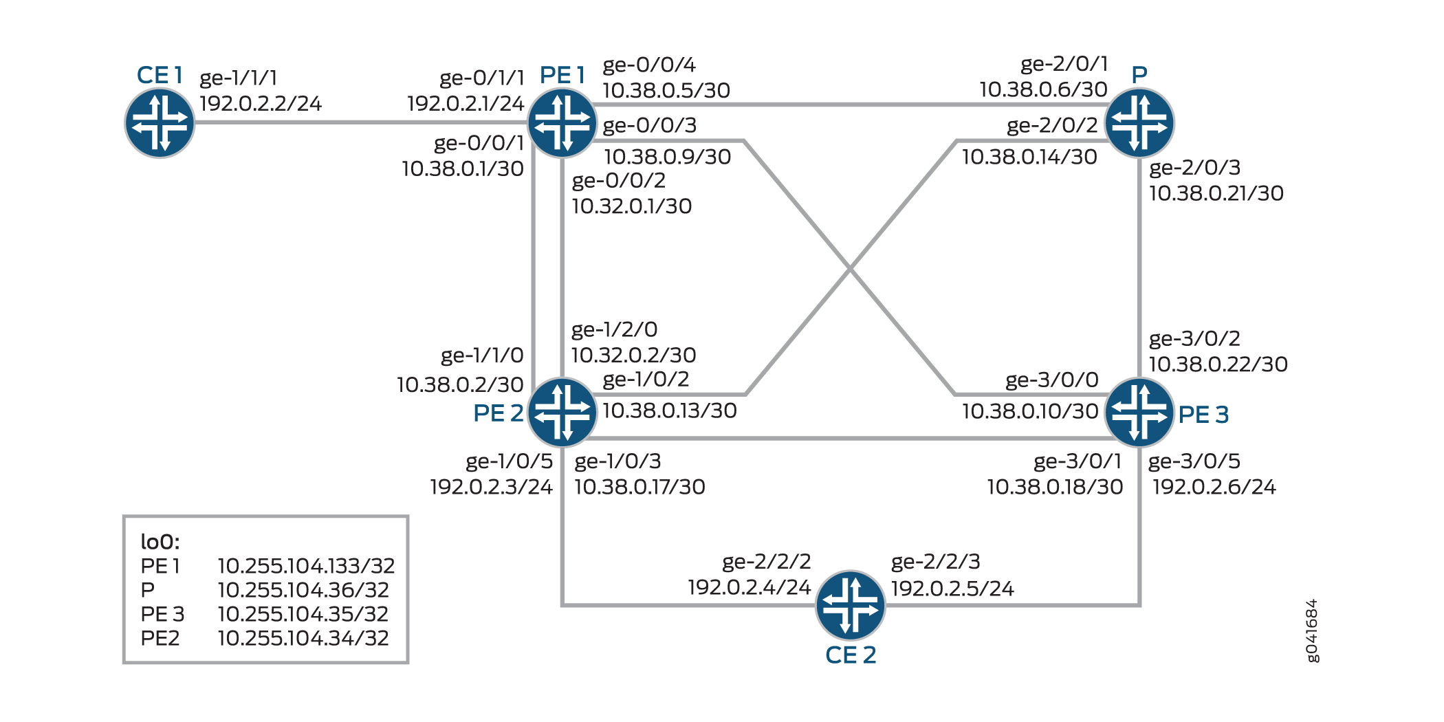
Configuration
CLI Quick Configuration
To quickly configure this example, copy the
following commands, paste them into a text file, remove any line breaks,
change any details necessary to match your network configuration,
and then copy and paste the commands into the CLI at the [edit] hierarchy level.
CE1
set interfaces ge-1/1/1 unit 0 family inet address 192.0.2.2/24
set interfaces ge-1/1/1 unit 0 family iso
set interfaces ge-1/1/1 unit 0 family mpls
set interfaces lo0 unit 0 family inet address 198.51.100.1/24
set protocols bgp group PE type external
set protocols bgp group PE peer-as 200
set protocols bgp group PE neighbor 192.0.2.1
set routing-options autonomous-system 100
PE1
set interfaces ge-0/0/1 unit 0 family inet address 10.38.0.1/30
set interfaces ge-0/0/1 unit 0 family mpls
set interfaces ge-0/0/2 unit 0 family inet address 10.38.0.5/30
set interfaces ge-0/0/2 unit 0 family mpls
set interfaces ge-0/0/3 unit 0 family inet address 10.38.0.9/30
set interfaces ge-0/0/3 unit 0 family mpls
set interfaces ge-0/0/4 unit 0 family inet address 10.32.0.1/30
set interfaces ge-0/0/4 unit 0 family mpls
set interfaces ge-0/1/1 unit 0 family inet address 192.0.2.1/24
set interfaces ge-0/1/1 unit 0 family mpls
set interfaces lo0 unit 0 family inet address 10.255.104.133/32
set chassis network-services enhanced-ip
set routing-options forwarding-table chained-composite-next-hop ingress l3vpn
set routing-options autonomous-system 200
set routing-options forwarding-table export lbpp
set protocols mpls interface 10.38.0.1/30
set protocols mpls interface 10.32.0.1/30
set protocols mpls interface 10.38.0.5/30
set protocols mpls interface 10.38.0.9/30
set protocols bgp group PEs type internal
set protocols bgp group PEs local-address 10.255.104.133
set protocols bgp group PEs family inet unicast
set protocols bgp group PEs family inet-vpn unicast
set protocols bgp group PEs neighbor 10.255.104.134 local-preference 200
set protocols bgp group PEs neighbor 10.255.104.135
set protocols ospf area 0.0.0.0 interface all
set protocols ospf area 0.0.0.0 interface fxp0.0 disable
set protocols ospf area 0.0.0.0 interface lo0.0 passive
set protocols ldp interface all
set protocols ldp interface fxp0.0 disable
set policy-options policy-statement lbpp then load-balance per-packet
set routing-instances vpn-a instance-type vrf
set routing-instances vpn-a interface ge-0/1/1.0
set routing-instances vpn-a route-distinguisher 200:1
set routing-instances vpn-a vrf-target target:200:1
set routing-instances vpn-a vrf-table-label
set routing-instances vpn-a protocols bgp group CE type external
set routing-instances vpn-a protocols bgp group CE peer-as 100
set routing-instances vpn-a protocols bgp group CE neighbor 192.0.2.2
PE2
set interfaces ge-1/0/2 unit 0 family inet address 10.38.0.13/30
set interfaces ge-1/0/2 unit 0 family mpls
set interfaces ge-1/0/3 unit 0 family inet address 10.32.0.17/30
set interfaces ge-1/0/3 unit 0 family mpls
set interfaces ge-1/0/5 unit 0 family inet address 192.0.2.3/24
set interfaces ge-1/0/5 unit 0 family mpls
set interfaces ge-1/1/0 unit 0 family inet address 10.38.0.2/30
set interfaces ge-1/1/0 unit 0 family mpls
set interfaces ge-1/2/0 unit 0 family inet address 10.32.0.2/30
set interfaces ge-1/2/0 unit 0 family mpls
set interfaces lo0 unit 0 family inet address 10.255.104.134/32
set chassis network-services enhanced-ip
set routing-options forwarding-table chained-composite-next-hop ingress l3vpn
set routing-instances vpn-a instance-type vrf
set routing-instances vpn-a interface ge-1/0/5.0
set routing-instances vpn-a route-distinguisher 200:2
set routing-instances vpn-a vrf-target target:200:1
set routing-instances vpn-a protocols bgp group CE type external
set routing-instances vpn-a protocols bgp group CE peer-as 300
set routing-instances vpn-a protocols bgp group CE neighbor 192.0.2.3
set protocols mpls interface 10.38.0.2/30
set protocols mpls interface 10.32.0.2/30
set protocols mpls interface 10.38.0.13/30
set protocols mpls interface 10.38.0.17/30
set protocols bgp group PEs type internal
set protocols bgp group PEs local-address 10.255.104.134
set protocols bgp group PEs family inet unicast
set protocols bgp group PEs family inet-vpn unicast
set protocols bgp group PEs neighbor 10.255.104.133
set protocols bgp group PEs neighbor 10.255.104.135
set protocols ospf area 0.0.0.0 interface all
set protocols ospf area 0.0.0.0 interface fxp0.0 disable
set protocols ospf area 0.0.0.0 interface lo0.0 passive
set protocols ldp interface all
set protocols ldp interface fxp0.0 disable
set routing-options autonomous-system 200
P
set interfaces ge-2/0/1 unit 0 family inet address 10.38.0.6/30
set interfaces ge-2/0/1 unit 0 family mpls
set interfaces ge-2/0/2 unit 0 family inet address 10.38.0.14/30
set interfaces ge-2/0/2 unit 0 family mpls
set interfaces ge-2/0/3 unit 0 family inet address 10.38.0.21/30
set interfaces ge-2/0/3 unit 0 family mpls
set interfaces lo0 unit 0 family inet address 10.255.104.136/32
set protocols mpls interface 10.38.0.6/30
set protocols mpls interface 10.38.0.14/30
set protocols mpls interface 10.38.0.21/30
set protocols bgp group PEs type internal
set protocols bgp group PEs local-address 10.255.104.136
set protocols bgp group PEs family inet unicast
set protocols bgp group PEs family inet-vpn unicast
set protocols bgp group PEs neighbor 10.255.104.133
set protocols ospf area 0.0.0.0 interface all
set protocols ospf area 0.0.0.0 interface fxp0.0 disable
set protocols ospf area 0.0.0.0 interface lo0.0 passive
set protocols ldp interface all
set protocols ldp interface fxp0.0 disable
set routing-options autonomous-system 200
PE3
set interfaces ge-3/0/0 unit 0 family inet address 10.38.0.10/30r0-r3
set interfaces ge-3/0/0 unit 0 family mpls
set interfaces ge-3/0/1 unit 0 family inet address 10.38.0.18/30r0-r1-2
set interfaces ge-3/0/1 unit 0 family mpls
set interfaces ge-3/0/2 unit 0 family inet address 10.38.0.22/30
set interfaces ge-3/0/2 unit 0 family mpls
set interfaces ge-3/0/5 unit 0 family inet address 192.0.2.6/24r0-r1-1
set interfaces ge-3/0/5 unit 0 family mpls
set interfaces lo0 unit 0 family inet address 10.255.104.135/32
set chassis network-services enhanced-mode
set routing-options forwarding-table chained-composite-next-hop ingress l3vpn
set routing-options autonomous-system 200
set routing-instances vpn-a instance-type vrf
set routing-instances vpn-a interface ge-3/0/5.0
set routing-instances vpn-a route-distinguisher 200:3
set routing-instances vpn-a vrf-target target:200:1
set routing-instances vpn-a protocols bgp group CE type external
set routing-instances vpn-a protocols bgp group CE peer-as 300
set routing-instances vpn-a protocols bgp group CE neighbor 192.0.2.5
set protocols mpls interface 10.38.0.10/30
set protocols mpls interface 10.38.0.18/30
set protocols mpls interface 10.38.0.22/30
set protocols bgp group PEs type internal
set protocols bgp group PEs local-address 10.255.104.135
set protocols bgp group PEs family inet unicast
set protocols bgp group PEs family inet-vpn unicast
set protocols bgp group PEs neighbor 10.255.104.133
set protocols bgp group PEs neighbor 10.255.104.134
set protocols ospf area 0.0.0.0 interface all
set protocols ospf area 0.0.0.0 interface fxp0.0 disable
set protocols ospf area 0.0.0.0 interface lo0.0 passive
set protocols ldp interface all
set protocols ldp interface fxp0.0 disable
CE2
set interfaces ge-2/2/2 unit 0 family inet address 192.0.2.4/24
set interfaces ge-2/2/2 unit 0 family mpls
set interfaces ge-2/2/3 unit 0 family inet address 192.0.2.5/24
set interfaces ge-2/2/3 unit 0 family mpls
set interfaces lo0 unit 0 family inet address 198.51.100.2/24
set protocols bgp group PE type external
set protocols bgp group PE metric-out 50
set protocols bgp group PE peer-as 200
set protocols bgp group PE export s2b
set protocols bgp group PE neighbor 192.0.2.4
set protocols bgp group PE neighbor 192.0.2.5
set policy-options policy-statement s2b from protocol direct
set policy-options policy-statement s2b then accept
set routing-options autonomous-system 300
Configuring Multipath Layer 3 VPN with Chained Composite Next Hops
Step-by-Step Procedure
The following example requires you to navigate various levels in the configuration hierarchy. For information about navigating the CLI, see Using the CLI Editor in Configuration Mode.
To configure basic Layer 3 VPN with chained CNH on the PE1 router:
Repeat this procedure for the PE2 and PE3 routers in the MPLS domain, after modifying the appropriate interface names, addresses, and any other parameters for each router.
Configure the interfaces on the PE1 router.
PE1 to CE1
[edit interfaces]user@PE1 # set ge-0/1/1 unit 0 family inet address 192.0.2.1/24 user@PE1 # set ge-0/1/1 unit 0 family mplsPE1 to PE2
[edit interfaces]user@PE1 # set ge-0/0/1 unit 0 family inet address 10.38.0.1/30 user@PE1 # set ge-0/0/1 unit 0 family mpls user@PE1 # set ge-0/0/2 unit 0 family inet address 10.38.0.5/30 user@PE1 # set ge-0/0/2 unit 0 family mplsPE1 to P
[edit interfaces]user@PE1 # set ge-0/0/4 unit 0 family inet address 10.32.0.1/30 user@PE1 # set ge-0/0/4 unit 0 family mplsPE1 to PE3
[edit interfaces]user@PE1 # set ge-0/0/3 unit 0 family inet address 10.38.0.9/30 user@PE1 # set ge-0/0/3 unit 0 family mplsLoopback interface
[edit interfaces]user@PE1 # set lo0 unit 0 family inet address 10.255.104.133/32Enable enhanced IP mode on the PE1 chassis.
[edit chassis]use@PE1# set network-services enhanced-ipEnable chained CNH on the global Layer 3 VPN.
[edit routing-options]use@PE1# set forwarding-table chained-composite-next-hop ingress l3vpnConfigure the autonomous system for PE1.
[edit routing-options]user@PE1# set autonomous-system 200Export the policy configured for load balancing.
[edit routing-options]user@PE1# set forwarding-table export lbppConfigure MPLS on the PE1 interfaces connecting to the P router and other PE routers.
[edit protocols]user@PE1# set mpls interface 10.38.0.1/30 user@PE1# set mpls interface 10.32.0.1/30 user@PE1# set mpls interface 10.38.0.5/30 user@PE1# set mpls interface 10.38.0.9/30Configure the IBGP group for PE1 to peer with the PE2 and PE3 routers.
[edit protocols]user@PE1# set bgp group PEs type internal user@PE1# set bgp group PEs local-address 10.255.104.133 user@PE1# set bgp group PEs family inet unicast user@PE1# set bgp group PEs family inet-vpn unicast user@PE1# set bgp group PEs neighbor 10.255.104.134 local-preference 200 user@PE1# set bgp group PEs neighbor 10.255.104.135Configure OSPF with traffic engineering capability on all the interfaces of PE1, excluding the management interface.
[edit protocols]user@PE1# set ospf area 0.0.0.0 interface all user@PE1# set ospf area 0.0.0.0 interface fxp0.0 disable user@PE1# set ospf area 0.0.0.0 interface lo0.0 passiveConfigure LDP on all the interfaces of PE1, excluding the management interface.
[edit protocols]user@PE1# set ldp interface all user@PE1# set ldp interface fxp0.0 disableConfigure a policy to load-balance traffic on a per packet basis.
[edit policy-options]user@PE1# set policy-statement lbpp then load-balance per-packetConfigure a VRF routing instance on the CE1-facing interface of PE1.
[edit routing-instances]user@PE1# set vpn-a instance-type vrf user@PE1# set vpn-a interface ge-0/1/1.0Configure the routing instance parameters.
[edit routing-instances]user@PE1# set vpn-a route-distinguisher 200:1 user@PE1# set vpn-a vrf-target target:200:1 user@PE1# set vpn-a vrf-table-labelConfigure an EBGP group for the routing instance, so PE1 can peer with CE1.
[edit routing-instances]user@PE1# set vpn-a protocols bgp group CE type external user@PE1# set vpn-a protocols bgp group CE peer-as 100 user@PE1# set vpn-a protocols bgp group CE neighbor 192.0.2.2
Results
From configuration mode, confirm your configuration
by entering the show chassis, show interfaces, show protocols, show routing-options, show routing-instances, and show policy-options commands.
If the output does not display the intended configuration, repeat
the instructions in this example to correct the configuration.
PE1
user@PE1# show chassis
network-services enhanced-ip;
user@PE1# show interfaces
ge-0/0/1 {
    unit 0 {
        family inet {
            address 10.38.0.1/30;
        }
        family mpls;
    }
}
ge-0/0/2 {
    unit 0 {
        family inet {
            address 10.38.0.5/30;
        }
        family mpls;
    }
}
ge-0/0/3 {
    unit 0 {
        family inet {
            address 10.38.0.9/30;
        }
        family mpls;
    }
}
ge-0/0/4 {
    unit 0 {
        family inet {
            address 10.32.0.1/30;
        }
        family mpls;
    }
}
ge-0/1/1 {
    unit 0 {
        family inet {
            address 192.0.2.1/24;
        }
        family mpls;
    }
}
lo0 {
    unit 0 {
        family inet {
            address 10.255.104.133/32;
        }
    }
}
user@PE1# show protocols
mpls {
    interface 10.38.0.1/30;
    interface 10.32.0.1/30;
    interface 10.38.0.5/30;
    interface 10.38.0.9/30;
}
bgp {
    group PEs {
        type internal;
        local-address 10.255.104.133;
        family inet {
            unicast;
        }
        family inet-vpn {
            unicast;
        }
        neighbor 10.255.104.134 {
            local-preference 200;
        }
        neighbor 10.255.104.135;
    }
}
ospf {
    area 0.0.0.0 {
        interface all;
        interface fxp0.0 {
            disable;
        }
        interface lo0.0 {
            passive;
        }
    }
}
ldp {
    interface all;
    interface fxp0.0 {
        disable;
    }
}
user@PE1# show routing-options
autonomous-system 200;
forwarding-table {
    export lbpp;
    chained-composite-next-hop {
        ingress {
            l3vpn;
        }
    }
}
user@PE1# show routing-instances
vpn-a {
    instance-type vrf;
    interface ge-0/1/1.0;
    route-distinguisher 200:1;
    vrf-target target:200:1;
    vrf-table-label;
    protocols {
        bgp {
            group CE {
                type external;
                peer-as 100;
                neighbor 192.0.2.2;
            }
        }
    }
}
user@PE1# show policy-options
policy-statement lbpp {
    then {
        load-balance per-packet;
    }
}
Verification
Confirm that the configuration is working properly.
Verifying the Routes
Purpose
Verify that the Layer 3 VPN prefixes toward PE1-PE2 point to chained CNHs.
Action
From operational mode, run the show route 198.51.100.2
table vpn-a extensive command.
user@PE1> show route 198.51.100.2 table vpn-a extensive


  vpn-a.inet.0: 7 destinations, 10 routes (7 active, 0 holddown, 0 hidden)
  198.51.100.2/24 (2 entries, 1 announced)
  TSI:
  KRT in-kernel 198.51.100.2/3 -> {composite(720)}
  Page 0 idx 0, (group CE type External) Type 1 val 938eaa8 (adv_entry)
     Advertised metrics:
       Nexthop: Self
       AS path: [200] 300 I
       Communities: target:200:1
  Path 198.51.100.2 from 10.255.104.133 Vector len 4.  Val: 0
          *BGP    Preference: 170/-101
                  Route Distinguisher: 200:2
                  Next hop type: Indirect
                  Address: 0x9391654
                  Next-hop reference count: 12
                  Source: 10.255.104.133
                  Next hop type: Router, Next hop index: 1048580
                  Next hop: 10.32.0.2 via ge-0/0/2.0
                  Session Id: 0x1
                  Next hop: 10.38.0.2 via ge-0/0/1.0, selected
                  Session Id: 0x3
                  Protocol next hop: 10.255.104.133
                  Push 300192
                  Composite next hop: 0x93918a4 718 INH Session ID: 0x9
                  Indirect next hop: 0x941c000 1048581 INH Session ID: 0x9
                  State: <Secondary Active Int Ext ProtectionCand>
                  Local AS:   200 Peer AS:   200
                  Age: 28   Metric: 50      Metric2: 1
                  Validation State: unverified
                  Task: BGP_203.0.113.1.133+57173
                  Announcement bits (2): 0-KRT 1-BGP_RT_Background
                  AS path: 300 I
                  Communities: target:200:1
                  Import Accepted
                  VPN Label: 300192
                  Localpref: 100
                  Router ID: 10.255.104.133
                  Primary Routing Table bgp.l3vpn.0
                  Composite next hops: 1
                          Protocol next hop: 10.255.104.133 Metric: 1
                          Push 300192
                          Composite next hop: 0x93918a4 718 INH Session ID: 0x9
                          Indirect next hop: 0x941c000 1048581 INH Session ID: 0x9
                          Indirect path forwarding next hops: 2
                                  Next hop type: Router
                                  Next hop: 10.32.0.2 via ge-1/0/0.0
                                  Session Id: 0x1
                                  Next hop: 10.38.0.2 via ge-1/1/2.0
                                  Session Id: 0x3
                    10.255.104.133/32 Originating RIB: inet.3
                      Metric: 1                       Node path count: 1
                      Forwarding nexthops: 2
                            Nexthop: 10.32.0.2 via ge-0/0/2.0
           BGP    Preference: 170/-101
                  Route Distinguisher: 200:3
                  Next hop type: Indirect
                  Address: 0x9391608
                  Next-hop reference count: 9
                  Source: 10.255.104.131
                  Next hop type: Router, Next hop index: 722
                  Next hop: 10.38.0.10 via ge-0/0/1.0, selected
                  Session Id: 0x4
                  Protocol next hop: 10.255.104.131
                  Push 299936
                  Composite next hop: 0x9391690 723 INH Session ID: 0xb
                  Indirect next hop: 0x941c0fc 1048583 INH Session ID: 0xb
                  State: <Secondary NotBest Int Ext ProtectionCand>
                  Inactive reason: Not Best in its group - Router ID
                  Local AS:   200 Peer AS:   200
                  Age: 28   Metric: 50      Metric2: 1
                  Validation State: unverified
                  Task: BGP_203.0.113.1.131+63797
                  AS path: 300 I
                  Communities: target:200:1
                  Import Accepted
                  VPN Label: 299936
                  Localpref: 100
                  Router ID: 10.255.104.131
                  Primary Routing Table bgp.l3vpn.0
                  Composite next hops: 1
                          Protocol next hop: 10.255.104.131 Metric: 1
                          Push 299936
                          Composite next hop: 0x9391690 723 INH Session ID: 0xb
                          Indirect next hop: 0x941c0fc 1048583 INH Session ID: 0xb
                          Indirect path forwarding next hops: 1
                                  Next hop type: Router
                                  Next hop: 10.38.0.10 via ge-1/0/2.0
                                  Session Id: 0x4
                    10.255.104.131/32 Originating RIB: inet.3
                      Metric: 1                       Node path count: 1
                      Forwarding nexthops: 1
                            Nexthop: 10.38.0.10 via ge-1/0/2.0
Meaning
The PE2 router is the CNH for PE1 to reach CE2.
Verifying Chained Next Hops on Direct PE-PE Connection
Purpose
Verify that chained next hop is generated for direct PE-PE connection on CE1.
Action
From operational mode, run the ping command.
user@CE1> ping 192.0.2.4
!!!!!
--- lsping statistics ---
5 packets transmitted, 5 packets received, 0% packet loss
Meaning
Chained CNH is enabled for the PE1 to PE2 connection.