Next-Hop Based Tunnels for Layer 3 VPNs
This topic describes configuring dynamic generic routing encapsulation (GRE) tunnel and a dynamic MPLS-over-UDP tunnel to support tunnel composite next hop. It also provides information on configuring reverse path forwarding to protect against anti-spoofing.
Configure Next-hop-based MPLS-over-GRE Dynamic Tunnels
Next-hop-based MPLS-over-GRE tunnels creates a tunnel composite next hop, an indirect next hop, and a forwarding next hop to resolve a tunnel destination route. You can configure next-hop-based MPLS-over-GRE tunnels along with firewall filter-based tunnel decapsulation.
On ACX Series, starting from Junos OS Evolved Release 24.2R1, you can configure dynamic GRE
next-hop-based tunnel by including the gre next-hop-based-tunnel statement at
the [edit routing-options dynamic-tunnels] hierarchy.
You can configure MPLS-over-GRE firewall filter-based decapsulation by including the
gre statement at the [edit firewall family family-name filter
filter-name term term-name then decapsulate] hierarchy level. Only decapsulate
action is supported in the firewall filter rule. MPLS-over-GRE firewall filter-based
decapsulation is supported only for family inet.
You can retrieve encapsulation tunnel statistics by configuring specific interval using the
interval statement at the [edit routing-options dynamic-tunnels
statistics] hierarchy level. You can also use the show dynamic-tunnels
database statistics command to view the statistics.
- Configure Encapsulation for Dynamic Next-hop Tunnel
- Configure Firewall Filters for Decapsulation
- Enabling Encapsulation Statistics
- Limitations
Configure Encapsulation for Dynamic Next-hop Tunnel
To configure encapsulation for dynamic next-hop tunnel, you need to include the gre
next-hop-based-tunnel statement at the [edit routing-options
dynamic-tunnels] hierarchy level.
The following is a sample configuration for MPLS-over-GRE Encapsulation:
[edit]
protocols {
bgp {
group IBGP {
type internal;
local-address 192.168.19.190;
family inet {
unicast;
}
}
neighbor 192.168.20.11;
}
}
routing-options {
dynamic-tunnels {
gre full-resolved-next-hop-based-tunnel;
gre next-hop-based-tunnel;
test_tunnel {
source-address 192.168.19.190;
gre;
destination-networks {
192.168.20.0/24 preference 4;
}
}
}
} Configure Firewall Filters for Decapsulation
In the following configuration, we match the SIP, DIP, protocol to match tunnel packets. Firewall filter needs to be mapped to the default routing instance.
With the action, PFE programs the router to strip off the tunnel headers and continue processing based on the inner header.
forwarding-options {
    family inet {
        filter {
            input f1;
        }
    }
}
firewall {
    family inet {
        filter f1 {
            term t1 {
                from {
                    source-address {
                        192.168.9.190/32;
                    }
                    destination-address {
                        10.255.10.11/32;
                    }                }
                then {
                    decapsulate {
                        gre;
                    }
                }
            }
            term t2 {
                then accept;
            }
        }
    }
}
Enabling Encapsulation Statistics
PFE has the capability to provide the encapsulation statistics at a packet and at a byte
count level. The byte count value includes the encapsulation header. By default, the
statistics are not enabled for the tunnel encapsulation as the counters used for statistics
is a shared resource. Therefore, you need to enable counter allocation by configuring the
encap-stats-enable CLI statement.
To enable the encapsulation statistics, configure the following CLI:
user@host# set system packet-forwarding-options tunnel encap-stats-enable
Limitations
The following are the limitations while configuring next hop-based MPLS-over-GRE Dynamic Tunnels on ACX Series:
-
TTL propagation for the dynamic next hop-based tunnel is not supported.
-
Class of service and MTU is not supported.
-
Path MTU discovery for both IPv4 and IPv6 encapsulation is not supported because flow cache is not maintained for the encapsulated packet at tunnel originating node.
-
Anti-spoofing at tunnel decapsulation for the inner source IP is not supported.
-
In a firewall filter rule, only
decapsulate mpls-in-udpanddecapsulate greis supported for tunnel decapsulation. Other firewall filter rules over the incoming core interface is not supported due to data path limitation. -
Firewall filter decapsulation rule supports only the default VRF.
-
Tunnel statistics per tunnel composite next hop level is not supported.
-
Statistics counter allocation is on a first come first serve (FCFS) basis. Upon a system restart or evo-pefmand restart, some of the counters might have a non-zero value post restart and the counters might not increment.
-
Prefix mask of /32 for IPv4 and /128 for IPv6 is only supported in decapsulation-based filter rules. Firewall filter prefix list in decapsulation-based filter rules is not supported.
-
Flexible-vlan-tagging is not supported.
-
Interface-based dynamic next-hop GRE tunnel is not supported.
-
The
set chassis loopback-dynamic-tunnelconfiguration statement is not applicable for the ACX platform because line-rate tunnel encapsulation and decapsulation are supported. -
IPv6 core is not supported.
Example: Configuring Next-Hop-Based Dynamic GRE Tunnels
This example shows how to configure a dynamic generic routing encapsulation (GRE) tunnel that includes a tunnel composite next hop (CNH) instead of an interface next hop. The next-hop-based dynamic GRE tunnel has a scaling advantage over the interface-based dynamic GRE tunnels.
Requirements
This example uses the following hardware and software components:
-
Five MX Series routers with MPCs and MICs.
-
Junos OS Release 16.2 or later running on the PE routers.
Before you begin:
-
Configure the device interfaces, including the loopback interface.
-
Configure the router ID and autonomous system number for the device.
-
Establish an internal BGP (IBGP) session with the remote PE device.
-
Establish OSPF peering among the devices.
Overview
Starting with Junos OS Release 16.2, a dynamic generic routing encapsulation (GRE) tunnel supports the creation of a tunnel composite next hop for every GRE tunnel configured.
By default, for every new dynamic GRE tunnel configured, a corresponding logical tunnel interface is created. This is called an interface-based dynamic tunnel and is the default mode for creating dynamic tunnels. On interface-based dynamic tunnel, the number of tunnels that can be configured on a device depends on the total number of interfaces supported on the device. The next-hop-based dynamic GRE tunnel removes the dependency on physical interfaces, and the GRE tunnel encapsulation is implemented as a next-hop instruction without creating a logical tunnel interface. This provides a scaling advantage for the number of dynamic tunnels that can be created on a device.
Starting in Junos OS Release 17.1, on MX Series routers with MPCs and MICs, the scaling limit of next-hop-based dynamic GRE tunnels is increased. The increased scaling values benefits data center networks, where a gateway router is required to communicate with a number of servers over an IP infrastructure; for example, in Contrail Networking.
At a given point in time, either the next-hop-based dynamic tunnel or the default interface-based dynamic GRE tunnel can exist on a device. A switchover from one tunnel mode to another deletes the existing tunnels and creates new tunnels in the new tunnel mode according to the supported scaling limits. Similarly, at a given point in time, for the same tunnel destination, the next-hop-based tunnel encapsulation type can either be GRE or UDP.
To enable the next-hop-based dynamic GRE tunnel, include the next-hop-based-tunnel statement at the [edit routing-options
dynamic-tunnels gre] hierarchy level.
The existing dynamic tunnel feature requires complete static configuration. Currently, the tunnel information received from peer devices in advertised routes is ignored. Starting in Junos OS Release 17.4R1, on MX Series routers, the next-hop-based dynamic GRE tunnels are signaled using BGP encapsulation extended community. BGP export policy is used to specify the tunnel types, advertise the sender side tunnel information, and parse and convey the receiver side tunnel information. A tunnel is created according to the received type tunnel community.
Multiple tunnel encapsulations are supported by BGP. On receiving multiple capability, the next-hop-based dynamic tunnel is created based on the configured BGP policy and tunnel preference. The tunnel preference should be consistent across both the tunnel ends for the tunnel to be set up. By default, MPLS-over-UDP (MPLSoUDP) tunnel is preferred over GRE tunnels. If dynamic tunnel configuration exists, it takes precedence over received tunnel community.
When configuring a next-hop-based dynamic GRE tunnel, be aware of the following considerations:
-
Dynamic tunnels creation is triggered in the IBGP protocol next-hop resolution process.
-
A switchover from the next-hop-based tunnel mode to the interface-based tunnel mode (and vice versa) is allowed, and this can impact network performance in terms of the supported IP tunnel scaling values in each mode.
-
RSVP automatic mesh tunnel is not supported with the next-hop-based dynamic tunnel configuration.
-
Dynamic GRE tunnel creation based upon new IPv4-mapped-IPv6 next hops is supported with this feature.
-
The following features are not supported with the next-hop-based dynamic GRE tunnel configuration:
-
RSVP automatic mesh
-
Logical systems
-
Per-tunnel traffic statistics collection on the sender (MX Series) side
-
QoS enforcement, such as policing and shaping, at the tunnel interface.
-
Path maximum transmission unit discovery
-
GRE key feature
-
GRE Operation, Administration, and Maintenance (OAM) for GRE keepalive messages.
-
Topology
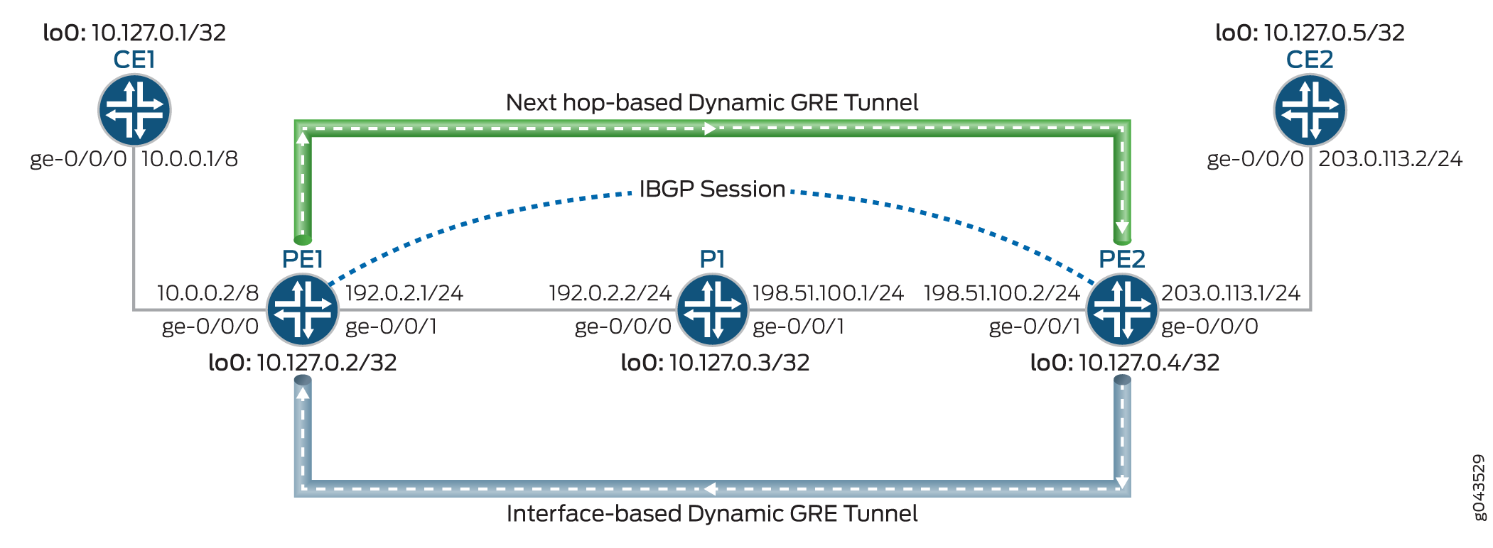
Figure 1 illustrates a Layer 3 VPN scenario over dynamic GRE tunnels. The customer edge (CE) devices, CE1 and CE2, connect to provider edge (PE) devices, PE1 and PE2, respectively. The PE devices are connected to a provider device ( Device P1), and an internal BGP (IBGP) session interconnects the two PE devices. Two dynamic GRE tunnels are configured between the PE devices. The dynamic tunnel from Device PE1 to Device PE2 is based on the next hop tunnel mode, and the dynamic tunnel from Device PE2 to Device PE1 is based on the interface tunnel mode.
The next-hop-based dynamic GRE tunnel is handled as follows:
-
After a next-hop-based dynamic GRE tunnel is configured, a tunnel destination mask route with a tunnel CNH is created for the protocol next hops in the inet.3 routing table. This IP tunnel route is withdrawn only when the dynamic tunnel configuration is deleted.
The tunnel CNH attributes include the following:
-
When Layer 3 VPN CNH is disabled—Source and destination address, encapsulation string, and VPN label.
-
When Layer 3 VPN CNH and per-prefix VPN label allocation are enabled—Source address, destination address, and encapsulation string.
-
When Layer 3 VPN CNH is enabled and per-prefix VPN label allocation is disabled—Source address, destination address, and encapsulation string. The route in this case is added to the other virtual routing and forwarding instance table with a secondary route.
-
-
The PE devices are interconnected using an IBGP session. The IBGP route next hop to a remote BGP neighbor is the protocol next hop, which is resolved using the tunnel mask route with the tunnel next hop.
-
After the next hop is resolved over the tunnel composite next hop, indirect next hops with forwarding next hops are created.
-
The tunnel CNH is used to forward the next hops of the indirect next hops.
Configuration
CLI Quick Configuration
To quickly configure this example, copy the following commands, paste them into a
text file, remove any line breaks, change any details necessary to match your
network configuration, copy and paste the commands into the CLI at the
[edit] hierarchy level, and then enter
commit from configuration mode.
CE1
set interfaces ge-0/0/0 unit 0 family inet address 10.0.0.1/8
set interfaces lo0 unit 0 family inet address 10.127.0.1/8
set routing-options router-id 10.127.0.1
set routing-options autonomous-system 65200
set protocols bgp group ce1-pe1 export export-loopback-direct
set protocols bgp group ce1-pe1 peer-as 65100
set protocols bgp group ce1-pe1 neighbor 10.0.0.2
set policy-options policy-statement export-loopback-direct term term-1 from interface lo0.0
set policy-options policy-statement export-loopback-direct term term-1 from route-filter 10.127.0.1/8 exact
set policy-options policy-statement export-loopback-direct term term-1 then accept
CE2
set interfaces ge-0/0/0 unit 0 family inet address 203.0.113.2/24
set interfaces lo0 unit 0 family inet address 10.127.0.5/32
set routing-options router-id 10.127.0.5
set routing-options autonomous-system 65200
set protocols bgp group ce1-pe1 export export-loopback-direct
set protocols bgp group ce1-pe1 peer-as 65100
set protocols bgp group ce1-pe1 neighbor 203.0.113.1
set policy-options policy-statement export-loopback-direct term term-1 from interface lo0.0
set policy-options policy-statement export-loopback-direct term term-1 from route-filter 10.127.0.5/8 exact
set policy-options policy-statement export-loopback-direct term term-1 then accept
PE1
set interfaces ge-0/0/0 unit 0 family inet address 10.0.0.2/8
set interfaces ge-0/0/1 unit 0 family inet address 192.0.2.1/24
set interfaces ge-0/0/1 unit 0 family mpls
set interfaces lo0 unit 0 family inet address 10.127.0.2/32
set routing-options static route 10.33.0.0/16 next-hop 192.0.2.2
set routing-options router-id 10.127.0.2
set routing-options autonomous-system 65100
set routing-options dynamic-tunnels gre next-hop-based-tunnel
set routing-options dynamic-tunnels gre-dyn-tunnel-to-pe2 source-address 10.127.0.2
set routing-options dynamic-tunnels gre-dyn-tunnel-to-pe2 gre
set routing-options dynamic-tunnels gre-dyn-tunnel-to-pe2 destination-networks 10.127.0.0/16
set protocols bgp group IBGP type internal
set protocols bgp group IBGP local-address 10.127.0.2
set protocols bgp group IBGP family inet-vpn unicast
set protocols bgp group IBGP neighbor 10.127.0.4
set protocols ospf area 0.0.0.0 interface ge-0/0/1.0
set protocols ospf area 0.0.0.0 interface lo0.0 passive
set routing-instances L3VPN-Over-GRE-PE1 instance-type vrf
set routing-instances L3VPN-Over-GRE-PE1 interface ge-0/0/0.0
set routing-instances L3VPN-Over-GRE-PE1 route-distinguisher 10.127.0.2:1
set routing-instances L3VPN-Over-GRE-PE1 vrf-target target:600:1
set routing-instances L3VPN-Over-GRE-PE1 protocols bgp group pe1-ce1 peer-as 65200
set routing-instances L3VPN-Over-GRE-PE1 protocols bgp group pe1-ce1 neighbor 10.0.0.1 as-override
P1
set interfaces ge-0/0/0 unit 0 family inet address 192.0.2.2/24
set interfaces ge-0/0/0 unit 0 family mpls
set interfaces ge-0/0/1 unit 0 family inet address 198.51.100.1/24
set interfaces ge-0/0/1 unit 0 family mpls
set interfaces lo0 unit 0 family inet address 10.127.0.3/32
set routing-options router-id 10.127.0.3
set routing-options autonomous-system 65100
set protocols ospf area 0.0.0.0 interface ge-0/0/0.0
set protocols ospf area 0.0.0.0 interface ge-0/0/1.0
set protocols ospf area 0.0.0.0 interface lo0.0 passive
PE2
set interfaces ge-0/0/0 unit 0 family inet address 203.0.113.1/24
set interfaces ge-0/0/1 unit 0 family inet address 198.51.100.2/24
set interfaces lo0 unit 0 family inet address 10.127.0.4/32
set routing-options nonstop-routing
set routing-options router-id 10.127.0.4
set routing-options autonomous-system 65100
set routing-options dynamic-tunnels gre-dyn-tunnel-to-pe1 source-address 10.127.0.4
set routing-options dynamic-tunnels gre-dyn-tunnel-to-pe1 gre
set routing-options dynamic-tunnels gre-dyn-tunnel-to-pe1 destination-networks 10.127.0.0/16
set protocols bgp group IBGP type internal
set protocols bgp group IBGP local-address 10.127.0.4
set protocols bgp group IBGP family inet-vpn unicast
set protocols bgp group IBGP neighbor 10.127.0.2
set protocols ospf area 0.0.0.0 interface ge-0/0/1.0
set protocols ospf area 0.0.0.0 interface lo0.0 passive
set routing-instances L3VPN-Over-GRE-PE2 instance-type vrf
set routing-instances L3VPN-Over-GRE-PE2 interface ge-0/0/0.0
set routing-instances L3VPN-Over-GRE-PE2 route-distinguisher 10.127.0.4:1
set routing-instances L3VPN-Over-GRE-PE2 vrf-target target:600:1
set routing-instances L3VPN-Over-GRE-PE2 protocols bgp group ebgp peer-as 65200
set routing-instances L3VPN-Over-GRE-PE2 protocols bgp group ebgp neighbor 203.0.113.2 as-override
Procedure
Step-by-Step Procedure
The following example requires that you navigate various levels in the configuration hierarchy. For information about navigating the CLI, see Using the CLI Editor in Configuration Mode in the CLI User Guide.
To configure Device PE1:
Configure the device interfaces including the loopback interface of the device.
[edit interfaces]
user@PE1# set ge-0/0/0 unit 0 family inet address 10.0.0.2/8
user@PE1# set ge-0/0/1 unit 0 family inet address 192.0.2.1/24
user@PE1# set ge-0/0/1 unit 0 family mpls
user@PE1# set lo0 unit 0 family inet address 10.127.0.2/8/32
Configure a static route for routes from Device PE1 with Device P1 as the next-hop destination.
[edit routing-options]
user@PE1# set static route 172.16.0.0/16 next-hop 192.0.2.2
Configure the router ID and autonomous system number for Device PE1.
[edit routing-options]
user@PE1# set router-id 10.127.0.2
user@PE1# set autonomous-system 65100
Configure IBGP peering between the PE devices.
[edit protocols]
user@PE1# set bgp group IBGP type internal
user@PE1# set bgp group IBGP local-address 10.127.0.2
user@PE1# set bgp group IBGP family inet-vpn unicast
user@PE1# set bgp group IBGP neighbor 10.127.0.4
Configure OSPF on all the interfaces of Device PE1, excluding the management interface.
[edit protocols]
user@PE1# set ospf area 0.0.0.0 interface ge-0/0/1.0
user@PE1# set ospf area 0.0.0.0 interface lo0.0 passive
Enable next-hop-based dynamic GRE tunnel configuration on Device PE1.
[edit routing-options]
user@PE1# set dynamic-tunnels gre next-hop-based-tunnel
Configure the dynamic GRE tunnel parameters from Device PE1 to Device PE2.
[edit routing-options]
user@PE1# set dynamic-tunnels gre-dyn-tunnel-to-pe2 source-address 10.127.0.2
user@PE1# set dynamic-tunnels gre-dyn-tunnel-to-pe2 gre
user@PE1# set dynamic-tunnels gre-dyn-tunnel-to-pe2 destination-networks 10.127.0.0/16
Export the load-balancing policy to the forwarding table.
[edit routing-options]
user@PE1# set forwarding-table export pplb
Configure a VRF routing instance on Device PE1 and other routing instance parameters.
[edit routing-instances]
user@PE1# set L3VPN-Over-GRE-PE1 instance-type vrf
user@PE1# set L3VPN-Over-GRE-PE1 interface ge-0/0/0.0
user@PE1# set L3VPN-Over-GRE-PE1 route-distinguisher 10.127.0.2:1
user@PE1# set L3VPN-Over-GRE-PE1 vrf-target target:600:1
Enable BGP in the routing instance configuration for peering with Device CE1.
[edit routing-instances]
user@PE1# set L3VPN-Over-GRE-PE1 protocols bgp group pe1-ce1 peer-as 65200
user@PE1# set L3VPN-Over-GRE-PE1 protocols bgp group pe1-ce1 neighbor 10.0.0.1 as-override
Results
From configuration mode, confirm your configuration by entering the show
interfaces, show routing-options, show
protocols, and show routing-instances commands. If
the output does not display the intended configuration, repeat the instructions
in this example to correct the configuration.
user@PE1# show interfaces
ge-0/0/0 {
    unit 0 {
        family inet {
            address 10.0.0.2/8;
        }
    }
}
ge-0/0/1 {
    unit 0 {
        family inet {
            address 192.0.2.1/24;
        }
        family mpls;
    }
}
lo0 {
    unit 0 {
        family inet {
            address 10.127.0.2/32;
        }
    }
}
user@PE1# show routing-options
static {
    route 172.16.0.0/16 next-hop 192.0.2.2;
}
router-id 10.127.0.2;
autonomous-system 65100;
dynamic-tunnels {
    gre next-hop-based-tunnel;
    gre-dyn-tunnel-to-pe2 {
        source-address 10.127.0.2;
        gre;
        destination-networks {
            10.127.0.0/16;
        }
    }
}
user@PE1# show protocols
bgp {
    group IBGP {
        type internal;
        local-address 127.0.0.2;
        family inet-vpn {
            unicast;
        }
        neighbor 127.0.0.4;
    }
}
ospf {
    area 0.0.0.0 {
        interface ge-0/0/1.0;
        interface lo0.0 {
            passive;
        }
    }
}
user@PE1# show routing-instances
L3VPN-Over-GRE-PE1 {
    instance-type vrf;
    interface ge-0/0/0.0;
    route-distinguisher 127.0.0.2:1;
    vrf-target target:600:1;
    protocols {
        bgp {
            group pe1-ce1 {
                peer-as 200;
                neighbor 10.0.0.1 {
                    as-override;
                }
            }
        }
    }
}
If you are done configuring the device, enter commit from
configuration mode.
Verification
Confirm that the configuration is working properly.
- Verifying the Connection Between PE Devices
- Verify the Dynamic Tunnel Routes on Device PE1
- Verify the Dynamic Tunnel Routes on Device PE2
- Verifying That the Routes Have the Expected Indirect-Next-Hop Flag
Verifying the Connection Between PE Devices
Purpose
Verify the BGP peering status between Device PE1 and Device PE2, and the BGP routes received from Device PE2.
Action
From operational mode, run the show bgp summary and show route receive-protocol bgp ip-address table bgp.l3vpn.0 commands.
user@PE1> show bgp summary
Groups: 2 Peers: 2 Down peers: 0
Table          Tot Paths  Act Paths Suppressed    History Damp State    Pending
bgp.l3vpn.0
                       2          2          0          0          0          0
Peer                     AS      InPkt     OutPkt    OutQ   Flaps Last Up/Dwn State|#Active/Received/Accepted/Damped...
127.0.0.4             100        139        136       0       0       58:23 Establ
  bgp.l3vpn.0: 2/2/2/0
  L3VPN-Over-GRE-PE1.inet.0: 2/2/2/0
10.0.0.1               200        135        136       0       0       58:53 Establ
L3VPN-Over-GRE-PE1.inet.0: 1/1/1/0user@PE1> show route receive-protocol bgp 10.127.0.4 table bgp.l3vpn.0 bgp.l3vpn.0: 2 destinations, 2 routes (2 active, 0 holddown, 0 hidden) Prefix Nexthop MED Lclpref AS path 10.127.0.4:1:127.0.0.5/8 * 127.0.0.4 65100 65200 I 10.127.0.4:1:203.0.113.0/24 * 127.0.0.4 65100 I
Meaning
-
In the first output, the BGP session state is
Establ, which means that the session is up and the PE devices are peered. -
In the second output, Device PE1 has learned two BGP routes from Device PE2.
Verify the Dynamic Tunnel Routes on Device PE1
Purpose
Verify the routes in the inet.3 routing table and the dynamic tunnel database information on Device PE1.
Action
From operational mode, run the show route table inet.3 and show dynamic-tunnels database terse commands.
user@PE1> show route table inet.3
inet.3: 2 destinations, 2 routes (2 active, 0 holddown, 0 hidden)
+ = Active Route, - = Last Active, * = Both

10.127.0.0/8      *[Tunnel/300] 01:01:45
                      Tunnel
10.127.0.4/8     *[Tunnel/300] 00:10:24
                      Tunnel Composite
user@PE1> show dynamic-tunnels database terse
Table: inet.3

Destination-network: 10.127.0.0/8
Destination         Source          Next-hop                  Type        Status
10.127.0.4/8      10.127.0.2     0xb395e70 nhid 612        gre         Up
Meaning
-
In the first output, because Device PE1 is configured with the next-hop-based dynamic GRE tunnel, a tunnel composite route is created for the inet.3 routing table route entry.
-
In the second output, the dynamic GRE tunnel created from Device PE1 to Device PE2 is up and has a next-hop ID assigned to it instead of a next-hop interface.
Verify the Dynamic Tunnel Routes on Device PE2
Purpose
Verify the routes in the inet.3 routing table and the dynamic tunnel database information on Device PE2.
Action
From operational mode, run the show route table inet.3 and show dynamic-tunnels database terse commands.
user@PE2> show route table inet.3
inet.3: 2 destinations, 2 routes (2 active, 0 holddown, 0 hidden)
+ = Active Route, - = Last Active, * = Both

10.127.0.0/8      *[Tunnel/300] 01:06:52
                      Tunnel
10.127.0.2/8     *[Tunnel/300] 01:04:45
                    > via gr-0/1/0.32769
user@PE1> show dynamic-tunnels database terse
Table: inet.3

Destination-network: 127.0.0.0/8
Destination         Source          Next-hop                  Type        10.
10.127.0.2/8      10.127.0.4     gr-0/1/0.32769            gre         Up
Meaning
-
In the first output, because Device PE2 has the default interface-based dynamic GRE tunnel configuration, a new interface is created for the inet.3 routing table route entry.
-
In the second output, the dynamic GRE tunnel created from Device PE2 to Device PE1 is up, and has the newly created interface name assigned to it.
Verifying That the Routes Have the Expected Indirect-Next-Hop Flag
Purpose
Verify that Device PE1 and Device PE2 are configured to maintain the indirect next hop to forwarding next-hop binding on the Packet Forwarding Engine forwarding table.
Action
From operational mode, run the show krt indirect-next-hop command on Device PE1 and Device PE2.
user@PE1> show krt indirect-next-hop
Indirect Nexthop:
Index: 1048574 Protocol next-hop address: 10.127.0.4
  RIB Table: bgp.l3vpn.0
  Label: Push 299792
  Policy Version: 1                     References: 2
  Locks: 3                              0xb2ab630
  Flags: 0x0
  INH Session ID: 0x0
  INH Version ID: 0
  Ref RIB Table: unknown
        Tunnel type: GRE, Reference count: 3, nhid: 612
        Destination address: 10.127.0.4, Source address: 10.127.0.2
        Tunnel id: 1, VPN Label: Push 299792, TTL action: prop-ttl
      IGP FRR Interesting proto count : 2
      Chain IGP FRR Node Num          : 1
         IGP Resolver node(hex)       : 0xb3c6d9c
         IGP Route handle(hex)        : 0xb1ad230      IGP rt_entry protocol        : Tunnel
IGP Actual Route handle(hex) : 0x0 IGP Actual rt_entry protocol : Anyuser@PE2> show krt indirect-next-hop
Indirect Nexthop:
Index: 1048574 Protocol next-hop address: 10.127.0.2
RIB Table: bgp.l3vpn.0
Label: Push 299792
Policy Version: 2 References: 2
Locks: 3 0xb2ab630
Flags: 0x2
INH Session ID: 0x145
INH Version ID: 0
Ref RIB Table: unknown
Next hop: via gr-0/1/0.32769
Label operation: Push 299792
Label TTL action: prop-ttl
Load balance label: Label 299792: None;
Label element ptr: 0xb395d40
Label parent element ptr: 0x0
Label element references: 1
Label element child references: 0
Label element lsp id: 0
Session Id: 0x144
IGP FRR Interesting proto count : 2
Chain IGP FRR Node Num : 1
IGP Resolver node(hex) : 0xb3d36e8
IGP Route handle(hex) : 0xb1af060 IGP rt_entry protocol : Tunnel
IGP Actual Route handle(hex) : 0x0 IGP Actual rt_entry protocol : AnyMeaning
-
In the first output, Device PE1 has a next-hop-based dynamic GRE tunnel to Device PE2.
-
In the second output, Device PE2 has an interface-based dynamic GRE tunnel to device PE1.
Troubleshooting
To troubleshoot the next-hop-based dynamic tunnels, see:
Troubleshooting Commands
Problem
The next-hop-based dynamic GRE tunnel configuration is not taking effect.
Solution
To troubleshoot the next-hop-based GRE tunnel configuration, use the following
traceoptions commands at the [edit
routing-options dynamic-tunnels] statement hierarchy:
-
traceoptions file file-name -
traceoptions file size file-size -
traceoptions flag all
For example:
[edit
                            routing-options dynamic-tunnels]
traceoptions {
file gre_dyn_pe1.wri size 4294967295;
flag all;
}
Example: Configuring Next-Hop-Based MPLS-Over-UDP Dynamic Tunnels
This example shows how to configure a dynamic MPLS-over-UDP tunnel that includes a tunnel composite next hop. The MPLS-over-UDP feature provides a scaling advantage on the number of IP tunnels supported on a device.
Starting in Junos OS Release 18.3R1,
MPLS-over-UDP tunnels are supported on PTX Series routers and QFX Series switches. For
every dynamic tunnel configured on a PTX router or a QFX switch, a tunnel composite next
hop, an indirect next hop, and a forwarding next hop is created to resolve the tunnel
destination route. You can also use policy control to resolve the dynamic tunnel over
select prefixes by including the forwarding-rib configuration statement at the [edit routing-options
dynamic-tunnels] hierarchy level.
Requirements
This example uses the following hardware and software components:
-
Five MX Series routers with MPCs and MICs.
-
Junos OS Release 16.2 or later running on the provider edge (PE) routers.
Before you begin:
-
Configure the device interfaces, including the loopback interface.
-
Configure the router ID and autonmous system number for the device.
-
Establish an internal BGP (IBGP) session with the remote PE device.
-
Establish OSPF peering among the devices.
Overview
Starting with Junos OS Release 16.2, a dynamic UDP tunnel supports the creation of a tunnel composite next hop for every UDP tunnel configured. These next-hop-based dynamic UDP tunnels are referred to as MPLS-over-UDP tunnels. The tunnel composite next hop are enabled by default for the MPLS-over-UDP tunnels.
MPLS-over-UDP tunnels can be bidirectional or unidirectional in nature.
-
Bidirectional—When the PE devices are connected over MPLS-over-UDP tunnels in both directions, it is called a bidirectional MPLS-over-UDP tunnel.
-
Unidirectional—When two PE devices are connected over MPLS-over-UDP tunnel in one direction, and over MPLS/IGP in the other direction, it is called an unidirectional MPLS-over-UDP tunnel.
Unidirectional MPLS-over-UDP tunnels are used in migration scenarios, or in cases where two PE devices provide connectivity to each other over two disjoint networks. Because reverse direction tunnel does not exist for unidirectional MPLS-over-UDP tunnels, you must configure a filter-based MPLS-over-UDP decapsulation on the remote PE device for forwarding the traffic.
Starting in Junos OS Release 18.2R1, on PTX series routers and QFX10000 with unidirectional MPLS-over-UDP tunnels, you must configure the remote PE device with an input filter for MPLS-over-UDP packets, and an action for decapsulating the IP and UDP headers for forwarding the packets in the reverse tunnel direction.
For example, on the remote PE device, Device PE2, the following configuration is required for unidirectional MPLS-over-UDP tunnels:
PE2
[edit firewall filter] user@host# set Decap_Filter term udp_decap from protocol udp user@host# set Decap_Filter term udp_decap from destination-port 6635 user@host# set Decap_Filter term udp_decap then count UDP_PKTS user@host# set Decap_Filter term udp_decap then decapsulate mpls-in-udp user@host# set Decap_Filter term def then count def_pkt user@host# set Decap_Filter term def then accept
In the above sample configuration, Decap_Filter is the name of the firewall filter used for MPLS-over-UDP decapsulation. The term udp_decap is the input filter for accepting UDP packets on the core-facing interface of Device PE2, and then decapsulate the MPLS-over-UDP packets to MPLS-over-IP packets for forwarding.
You can use the existing firewall operational mode commands, such as show
firewall filter to view the filter-based MPLS-over-UDP
decapsulation.
For example:
user@host >show firewall filter Decap_Filter Filter: Decap_Filter Counters: Name Bytes Packets UDP_PKTS 16744 149 def_pkt 13049 136
For unidirectional MPLS-over-UDP tunnels:
-
Only IPv4 address is supported as the outer header. Filter-based MPLS-over-UDP decapsulation does not support IPv6 address in the outer header.
-
Only the default routing instance is supported after decapsulation.
Starting in Junos OS Release 17.1, on MX Series routers with MPCs and MICs, the scaling limit of MPLS-over-UDP tunnels is increased.
Starting in Junos Release 19.2R1, on MX Series routers with MPCs and MICs, carrier supporting carrier (CSC) architecture can be deployed with MPLS-over-UDP tunnels carrying MPLS traffic over dynamic IPv4 UDP tunnels that are established between supporting carrier's PE devices. With this enhancement, the scaling advantage that the MPLS-over-UDP tunnels provided is further increased. The CSC support with MPLS-over-UDP tunnel is not supported for IPv6 UDP tunnel.
The existing dynamic tunnel feature requires complete static configuration. Currently, the tunnel information received from peer devices in advertised routes is ignored. Starting in Junos OS Release 17.4R1, on MX Series routers, the next-hop-based dynamic MPLS-over-UDP tunnels are signaled using BGP encapsulation extended community. BGP export policy is used to specify the tunnel types, advertise the sender side tunnel information, and parse and convey the receiver side tunnel information. A tunnel is created according to the received type tunnel community.
Multiple tunnel encapsulations are supported by BGP. On receiving multiple capability, the next-hop-based dynamic tunnel is created based on the configured BGP policy and tunnel preference. The tunnel preference should be consistent across both the tunnel ends for the tunnel to be set up. By default, MPLS-over-UDP tunnel is preferred over GRE tunnels. If dynamic tunnel configuration exists, it takes precedence over received tunnel community.
When configuring a next-hop-based dynamic MPLS-over-UDP tunnel, be aware of the following considerations:
-
An IBGP session must be configured between the PE devices.
-
A switchover between the next-hop-based dynamic tunnel encapsulations (UDP and GRE) is allowed, and this can impact network performance in terms of the supported IP tunnel scaling values in each mode.
-
Having both GRE and UDP next-hop-based dynamic tunnel encapsulation types for the same tunnel destination leads to a commit failure.
-
For unidirectional MPLS-over-UDP tunnels, you must explicitly configure filter-based MPLS-over-UDP decapsulation on the remote PE device for the packets to be forwarded.
-
Graceful Routing Engine switchover (GRES) is supported with MPLS-over-UDP, and the MPLS-over-UDP tunnel type flags are unified ISSU and NSR compliant.
-
MPLS-over-UDP tunnels are supported on virtual MX (vMX) in Lite mode.
-
MPLS-over-UDP tunnels support dynamic GRE tunnel creation based upon new IPv4-mapped-IPv6 next hops.
-
MPLS-over-UDP tunnel are supported in interoperability with contrail, wherein the MPLS-over-UDP tunnels are created from the contrail vRouter to an MX gateway. To enable this, the following community is required to be advertised in the route from the MX Series router to the contrail vRouter:
[edit policy-options community] udp members 0x030c:64512:13;
At a given point in time, only one tunnel type is supported on the contrail vRouter—next-hop-based dynamic GRE tunnels, MPLS-over-UDP tunnels, or VXLAN.
-
The following features are not supported with the next-hop-based dynamic MPLS-over-UDP tunnel configuration:
-
RSVP automatic mesh
-
Plain IPV6 GRE and UDP tunnel configuration
-
Logical systems
-
Topology
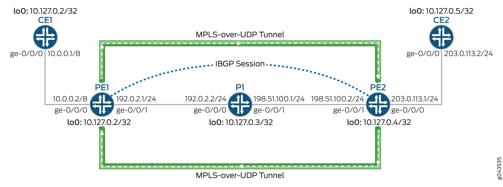
Figure 2 illustrates a Layer 3 VPN scenario over dynamic MPLS-over-UDP tunnels. The customer edge (CE) devices, CE1 and CE2, connect to provider edge (PE) devices, PE1 and PE2, respectively. The PE devices are connected to a provider device (Device P1), and an internal BGP (IBGP) session interconnects the two PE devices. A dynamic next-hop-based bidirectional MPL-over-UDP tunnel is configured between the PE devices.
The MPLS-over-UDP tunnel is handled as follows:
-
After a MPLS-over-UDP tunnel is configured, a tunnel destination mask route with a tunnel composite next hop is created for the tunnel in the inet.3 routing table. This IP tunnel route is withdrawn only when the dynamic tunnel configuration is deleted.
The tunnel composite next-hop attributes include the following:
-
When Layer 3 VPN composite next hop is disabled—Source and destination address, encapsulation string, and VPN label.
-
When Layer 3 VPN composite next hop and per-prefix VPN label allocation are enabled—Source address, destination address, and encapsulation string.
-
When Layer 3 VPN composite next hop is enabled and per-prefix VPN label allocation is disabled—Source address, destination address, and encapsulation string. The route in this case is added to the other virtual routing and forwarding instance table with a secondary route.
-
-
The PE devices are interconnected using an IBGP session. The IBGP route next hop to a remote BGP neighbor is the protocol next hop, which is resolved using the tunnel mask route with the tunnel next hop.
-
After the protocol next hop is resolved over the tunnel composite next hop, indirect next hops with forwarding next hops are created.
-
The tunnel composite next hop is used to forward the next hops of the indirect next hops.
Configuration
CLI Quick Configuration
To quickly configure this example, copy the following commands, paste them into a
text file, remove any line breaks, change any details necessary to match your
network configuration, copy and paste the commands into the CLI at the
[edit] hierarchy level, and then enter
commit from configuration mode.
CE1
set interfaces ge-0/0/0 unit 0 family inet address 10.0.0.1/8 set interfaces lo0 unit 0 family inet address 10.127.0.1/32 set routing-options router-id 10.127.0.1 set routing-options autonomous-system 65200 set protocols bgp group ce1-pe1 export export-loopback-direct set protocols bgp group ce1-pe1 peer-as 100 set protocols bgp group ce1-pe1 neighbor 10.0.0.2 set policy-options policy-statement export-loopback-direct term term-1 from interface lo0.0 set policy-options policy-statement export-loopback-direct term term-1 from route-filter 10.127.0.1/32 exact set policy-options policy-statement export-loopback-direct term term-1 then accept
CE2
set interfaces ge-0/0/0 unit 0 family inet address 203.0.113.2/24 set interfaces lo0 unit 0 family inet address 10.127.0.5/32 set routing-options router-id 10.127.0.5 set routing-options autonomous-system 65200 set protocols bgp group ce1-pe1 export export-loopback-direct set protocols bgp group ce1-pe1 peer-as 65100 set protocols bgp group ce1-pe1 neighbor 203.0.113.1 set policy-options policy-statement export-loopback-direct term term-1 from interface lo0.0 set policy-options policy-statement export-loopback-direct term term-1 from route-filter 10.127.0.5/32 exact set policy-options policy-statement export-loopback-direct term term-1 then accept
PE1
set interfaces ge-0/0/0 unit 0 family inet address 10.0.0.2/8 set interfaces ge-0/0/1 unit 0 family inet address 192.0.2.1/24 set interfaces ge-0/0/1 unit 0 family mpls set interfaces lo0 unit 0 family inet address 10.127.0.2/32 set routing-options static route 10.33.0/16 next-hop 192.0.2.2 set routing-options router-id 10.127.0.2 set routing-options autonomous-system 65100 set routing-options forwarding-table export pplb set routing-options dynamic-tunnels gre next-hop-based-tunnel set routing-options dynamic-tunnels udp-dyn-tunnel-to-pe2 source-address 10.127.0.2 set routing-options dynamic-tunnels udp-dyn-tunnel-to-pe2 udp set routing-options dynamic-tunnels udp-dyn-tunnel-to-pe2 destination-networks 10.127.0.0/24 set protocols bgp group IBGP type internal set protocols bgp group IBGP local-address 10.127.0.2 set protocols bgp group IBGP family inet-vpn unicast set protocols bgp group IBGP neighbor 10.127.0.4 set protocols ospf area 0.0.0.0 interface ge-0/0/1.0 set protocols ospf area 0.0.0.0 interface lo0.0 passive set routing-instances MPLS-over-UDP-PE1 instance-type vrf set routing-instances MPLS-over-UDP-PE1 interface ge-0/0/0.0 set routing-instances MPLS-over-UDP-PE1 route-distinguisher 10.127.0.2:1 set routing-instances MPLS-over-UDP-PE1 vrf-target target:600:1 set routing-instances MPLS-over-UDP-PE1 protocols bgp group pe1-ce1 peer-as 65200 set routing-instances MPLS-over-UDP-PE1 protocols bgp group pe1-ce1 neighbor 10.0.0.1 as-override
P1
set interfaces ge-0/0/0 unit 0 family inet address 192.0.2.2/24 set interfaces ge-0/0/0 unit 0 family mpls set interfaces ge-0/0/1 unit 0 family inet address 198.51.100.1/24 set interfaces ge-0/0/1 unit 0 family mpls set interfaces lo0 unit 0 family inet address 10.127.0.3/32 set routing-options router-id 10.127.0.3 set routing-options autonomous-system 65100 set protocols ospf area 0.0.0.0 interface ge-0/0/0.0 set protocols ospf area 0.0.0.0 interface ge-0/0/1.0 set protocols ospf area 0.0.0.0 interface lo0.0 passive
PE2
set interfaces ge-0/0/0 unit 0 family inet address 203.0.113.1/24 set interfaces ge-0/0/1 unit 0 family inet address 198.51.100.2/24 set interfaces ge-0/0/1 unit 0 family mpls set interfaces lo0 unit 0 family inet address 10.127.0.4/8 set routing-options nonstop-routing set routing-options router-id 10.127.0.4 set routing-options autonomous-system 65100 set routing-options forwarding-table export pplb set routing-options dynamic-tunnels udp-dyn-tunnel-to-pe1 source-address 10.127.0.4 set routing-options dynamic-tunnels udp-dyn-tunnel-to-pe1 udp set routing-options dynamic-tunnels udp-dyn-tunnel-to-pe1 destination-networks 10.127.0.0/24 set protocols bgp group IBGP type internal set protocols bgp group IBGP local-address 10.127.0.4 set protocols bgp group IBGP family inet-vpn unicast set protocols bgp group IBGP neighbor 10.127.0.2 set protocols ospf area 0.0.0.0 interface ge-0/0/1.0 set protocols ospf area 0.0.0.0 interface lo0.0 passive set routing-instances MPLS-over-UDP-PE2 instance-type vrf set routing-instances MPLS-over-UDP-PE2 interface ge-0/0/0.0 set routing-instances MPLS-over-UDP-PE2 route-distinguisher 10.127.0.4:1 set routing-instances MPLS-over-UDP-PE2 vrf-target target:600:1 set routing-instances MPLS-over-UDP-PE2 protocols bgp group ebgp peer-as 65200 set routing-instances MPLS-over-UDP-PE2 protocols bgp group ebgp neighbor 203.0.113.2 as-override
Procedure
Step-by-Step Procedure
The following example requires that you navigate various levels in the configuration hierarchy. For information about navigating the CLI, see Using the CLI Editor in Configuration Mode in the CLI User Guide.
To configure Device PE1:
-
Configure the device interfaces including the loopback interface of the device.
[edit interfaces] user@PE1# set ge-0/0/0 unit 0 family inet address 10.0.0.2/8 user@PE1# set ge-0/0/1 unit 0 family inet address 192.0.2.1/24 user@PE1# set ge-0/0/1 unit 0 family mpls user@PE1# set lo0 unit 0 family inet address 10.127.0.2/8
-
Configure a static route for routes from Device PE1 with Device P1 as the next-hop destination.
[edit routing-options] user@PE1# set static route 10.33.0.0/16 next-hop 192.0.2.2
-
Configure the router-ID and autonomous system number for Device PE1.
[edit routing-options] user@PE1# set router-id 10.127.0.2 user@PE1# set autonomous-system 65100
-
(PTX Series only) Configure policy control to resolve the MPLS-over-UDP dynamic tunnel route over select prefixes.
[edit routing-options dynamic-tunnels] user@PTX-PE1# set forwarding-rib inet.0 inet-import dynamic-tunnel-fwd-route-import
-
(PTX Series only) Configure the inet-import policy for resolving dynamic tunnel destination routes over .
[edit policy-options]
user@PTX-PE1# set policy-statement dynamic-tunnel-fwd-route-import term 1 from route-filter 10.127.0.4/32 exact
user@PTX-PE1# set policy-statement dynamic-tunnel-fwd-route-import term 1 then accept
user@PTX-PE1# set policy-options policy-statement dynamic-tunnel-fwd-route-import then reject
-
Configure IBGP peering between the PE devices.
[edit protocols]
user@PE1# set bgp group IBGP type internal
user@PE1# set bgp group IBGP local-address 10.127.0.2
user@PE1# set bgp group IBGP family inet-vpn unicast
user@PE1# set bgp group IBGP neighbor 10.127.0.4
-
Configure OSPF on all the interfaces of Device PE1, excluding the management interface.
[edit protocols]
user@PE1# set ospf area 0.0.0.0 interface ge-0/0/1.0
user@PE1# set ospf area 0.0.0.0 interface lo0.0 passive
-
Enable next-hop-based dynamic GRE tunnel configuration on Device PE1.
Note:This step is required only for illustrating the implementation difference between next-hop-based dynamic GRE tunnels and MPLS-over-UDP tunnels.
[edit routing-options]
user@PE1# set dynamic-tunnels gre next-hop-based-tunnel
-
Configure the MPLS-over-UDP tunnel parameters from Device PE1 to Device PE2.
[edit routing-options]
user@PE1# set dynamic-tunnels udp-dyn-tunnel-to-pe2 source-address 10.127.0.2
user@PE1# set dynamic-tunnels udp-dyn-tunnel-to-pe2 udp
user@PE1# set dynamic-tunnels udp-dyn-tunnel-to-pe2 destination-networks 10.127.0.0/24
-
Configure a VRF routing instance on Device PE1 and other routing instance parameters.
[edit routing-instances]
user@PE1# set MPLS-over-UDP-PE1 instance-type vrf
user@PE1# set MPLS-over-UDP-PE1 interface ge-0/0/0.0
user@PE1# set MPLS-over-UDP-PE1 route-distinguisher 10.127.0.2:1
user@PE1# set MPLS-over-UDP-PE1 vrf-target target:600:1
-
Enable BGP in the routing instance configuration for peering with Device CE1.
[edit routing-instances]
user@PE1# set MPLS-over-UDP-PE1 protocols bgp group pe1-ce1 peer-as 65200
user@PE1# set MPLS-over-UDP-PE1 protocols bgp group pe1-ce1 neighbor 10.0.0.1 as-override
Results
From configuration mode, confirm your configuration by entering the show
interfaces, show routing-options, show
protocols, and show routing-instances commands. If
the output does not display the intended configuration, repeat the instructions
in this example to correct the configuration.
user@PE1# show interfaces
ge-0/0/0 {
    unit 0 {
        family inet {
            address 10.0.0.2/8;
        }
    }
}
ge-0/0/1 {
    unit 0 {
        family inet {
            address 192.0.2.1/24;
        }
        family mpls;
    }
}
lo0 {
    unit 0 {
        family inet {
            address 10.127.0.2/32;
        }
    }
}
user@PE1# show routing-options
static {
    route 10.33.0.0/16 next-hop 192.0.2.2;
}
router-id 10.127.0.2;
autonomous-system 65100;
forwarding-table {
    export pplb;
}
dynamic-tunnels {
    gre next-hop-based-tunnel;
    udp-dyn-tunnel-to-pe2 {
        source-address 10.127.0.2;
        udp;
        destination-networks {
            10.127.0.0/24;
        }
    }
}
user@PE1# show protocols
bgp {
    group IBGP {
        type internal;
        local-address 10.127.0.2;
        family inet-vpn {
            unicast;
        }
        neighbor 10.127.0.4;
    }
}
ospf {
    area 0.0.0.0 {
        interface ge-0/0/1.0;
        interface lo0.0 {
            passive;
        }
    }
}
user@PE1# show routing-instances
MPLS-over-UDP-PE1 {
    instance-type vrf;
    interface ge-0/0/0.0;
    route-distinguisher 10.127.0.2:1;
    vrf-target target:600:1;
    protocols {
        bgp {
            group pe1-ce1 {
                peer-as 65200;
                neighbor 10.0.0.1 {
                    as-override;
                }
            }
        }
    }
}
If you are done configuring the device, enter commit from
configuration mode.
Verification
Confirm that the configuration is working properly.
- Verifying the Connection Between PE Devices
- Verify the Dynamic Tunnel Routes on Device PE1
- Verify the Dynamic Tunnel Routes on Device PE2
- Verifying That the Routes Have the Expected Indirect-Next-Hop Flag
Verifying the Connection Between PE Devices
Purpose
Verify the BGP peering status between Device PE1 and Device PE2, and the BGP routes received from Device PE2.
Action
From operational mode, run the show bgp summary and show route receive-protocol bgp ip-address table bgp.l3vpn.0 commands.
user@PE1> show bgp summary
Groups: 2 Peers: 2 Down peers: 0
Table          Tot Paths  Act Paths Suppressed    History Damp State    Pending
bgp.l3vpn.0
                       2          2          0          0          0          0
Peer                     AS      InPkt     OutPkt    OutQ   Flaps Last Up/Dwn State|#Active/Received/Accepted/Damped...
10.127.0.4             65100        139        136       0       0       58:23 Establ
  bgp.l3vpn.0: 2/2/2/0
  MPLS-over-UDP-PE1.inet.0: 2/2/2/0
10.10.0.1               65200        135        136       0       0       58:53 Establ
MPLS-over-UDP-PE1.inet.0: 1/1/1/0user@PE1> show route receive-protocol bgp 10.127.0.4 table bgp.l3vpn.0 bgp.l3vpn.0: 2 destinations, 2 routes (2 active, 0 holddown, 0 hidden) Prefix Nexthop MED Lclpref AS path 10.127.0.4:1:127.0.0.5/8 * 10.127.0.4 65100 65200 I
Meaning
-
In the first output, the BGP session state is
Establ, which means that the session is up and the PE devices are peered. -
In the second output, Device PE1 has learned a BGP route from Device PE2.
Verify the Dynamic Tunnel Routes on Device PE1
Purpose
Verify the routes in the inet.3 routing table and the dynamic tunnel database information on Device PE1.
Action
From operational mode, run the show route table inet.3, show dynamic-tunnels database terse, show dynamic-tunnels database, and show dynamic-tunnels database summary commands.
user@PE1> show route table inet.3
inet.3: 2 destinations, 2 routes (2 active, 0 holddown, 0 hidden)
+ = Active Route, - = Last Active, * = Both
10.127.0.0/24     *[Tunnel/300] 00:21:18
                      Tunnel
127.0.0.4/8     *[Tunnel/300] 00:21:18
Tunnel Compositeuser@PE1> show dynamic-tunnels database terse Table: inet.3 Destination-network: 10.127.0.0/24 Destination Source Next-hop Type Status 10.127.0.4/8 10.127.0.2 0xb395b10 nhid 613 udp Up
user@PE1> show dynamic-tunnels database
Table: inet.3
. . .
Tunnel to: 10.127.0.4/32
  Reference count: 2
  Next-hop type: UDP
    Source address: 10.127.0.2 Tunnel Id: 2
    Next hop: tunnel-composite, 0xb395b10, nhid 613
      VPN Label: Push 299776 Reference count: 3
      Traffic Statistics: Packets 0, Bytes 0
State: Upuser@PE1> show dynamic-tunnels database summary Dynamic Tunnels, Total 1 displayed GRE Tunnel: Active Tunnel Mode, Next Hop Base IFL Based, Total 0 displayed, Up 0, Down 0 Nexthop Based, Total 0 displayed, Up 0, Down 0 RSVP Tunnel: Total 0 displayed UDP Tunnel: Total 1 displayed, Up 1, Down 0
Meaning
-
In the first output, because Device PE1 is configured with the MPLS-over-UDP tunnel, a tunnel composite route is created for the inet.3 routing table route entry.
-
In the remaining outputs, the MPLS-over-UDP tunnel is displayed with the tunnel encapsulation type, tunnel next hop parameters, and tunnel status.
Verify the Dynamic Tunnel Routes on Device PE2
Purpose
Verify the routes in the inet.3 routing table and the dynamic tunnel database information on Device PE2.
Action
From operational mode, run the show route table inet.3, and the show dynamic-tunnels database terse commands.
user@PE2> show route table inet.3
inet.3: 2 destinations, 2 routes (2 active, 0 holddown, 0 hidden)
+ = Active Route, - = Last Active, * = Both

10.127.0.0/24      *[Tunnel/300] 00:39:31
                      Tunnel
10.127.0.2/32     *[Tunnel/300] 00:24:53
Tunnel Compositeuser@PE1> show dynamic-tunnels database terse Table: inet.3 Destination-network: 127.0.0.0/8 Destination Source Next-hop Type Status 10.127.0.2/32 10.127.0.4 0xb395450 nhid 615 udp Up
Meaning
The outputs show the MPLS-over-UDP tunnel creation and the next-hop ID assigned as the next-hop interface, similar to Device PE1.
Verifying That the Routes Have the Expected Indirect-Next-Hop Flag
Purpose
Verify that Device PE1 and Device PE2 are configured to maintain the indirect next hop to forwarding next-hop binding on the Packet Forwarding Engine forwarding table.
Action
From operational mode, run the show krt indirect-next-hop command on Device PE1 and Device PE2.
user@PE1> show krt indirect-next-hop
Indirect Nexthop:
Index: 1048574 Protocol next-hop address: 10.127.0.4
  RIB Table: bgp.l3vpn.0
  Label: Push 299776
  Policy Version: 1                     References: 1
  Locks: 3                              0xb2ab630
  Flags: 0x0
  INH Session ID: 0x0
  INH Version ID: 0
  Ref RIB Table: unknown
        Tunnel type: UDP, Reference count: 3, nhid: 613
        Destination address: 10.127.0.4, Source address: 10.127.0.2
        Tunnel id: 2, VPN Label: Push 299776, TTL action: prop-ttl
      IGP FRR Interesting proto count : 1
      Chain IGP FRR Node Num          : 1
         IGP Resolver node(hex)       : 0xb3c70dc
         IGP Route handle(hex)        : 0xb1ae688      IGP rt_entry protocol        : Tunnel
IGP Actual Route handle(hex) : 0x0 IGP Actual rt_entry protocol : Anyuser@PE2> show krt indirect-next-hop
Indirect Nexthop:
Index: 1048575 Protocol next-hop address: 10.127.0.2
RIB Table: bgp.l3vpn.0
Label: Push 299776
Policy Version: 1 References: 2
Locks: 3 0xb2ab740
Flags: 0x0
INH Session ID: 0x0
INH Version ID: 0
Ref RIB Table: unknown
Tunnel type: UDP, Reference count: 3, nhid: 615
Destination address: 10.127.0.2, Source address: 10.127.0.4
Tunnel id: 1, VPN Label: Push 299776, TTL action: prop-ttl
IGP FRR Interesting proto count : 2
Chain IGP FRR Node Num : 1
IGP Resolver node(hex) : 0xb3d3a28
IGP Route handle(hex) : 0xb1ae634 IGP rt_entry protocol : Tunnel
IGP Actual Route handle(hex) : 0x0 IGP Actual rt_entry protocol : AnyMeaning
The outputs show that a next-hop-based dynamic MPLS-over-UDP tunnel is created between the PE devices.
Troubleshooting
To troubleshoot the next-hop-based dynamic tunnels, see:
Troubleshooting Commands
Problem
The next-hop-based dynamic MPLS-over-UDP tunnel configuration is not taking effect.
Solution
To troubleshoot the next-hop-based MPLS-over-UDP tunnel configuration, use
the following traceroute commands at the [edit
routing-options dynamic-tunnels] statement hierarchy:
-
traceoptions file file-name -
traceoptions file size file-size -
traceoptions flag all
For example:
[edit
                            routing-options dynamic-tunnels]
traceoptions {
file udp_dyn_pe1.wri size 4294967295;
flag all;
}
Anti-Spoofing Protection for Next-Hop-Based Dynamic Tunnels Overview
With the rise in deployment of high-scale IP tunnels in data centers, there is a need to add security measures that allow users to limit malicious traffic from compromised virtual machines (VMs). One possible attack is the injecting of traffic into an arbitrary customer VPN from a compromised server through the gateway router. In such cases, anti-spoofing checks on IP tunnels ensure that only legitimate sources are injecting traffic into data centers from their designated IP tunnels.
Next-hop-based dynamic IP tunnels create a tunnel composite next hop for every dynamic tunnel created on the device. Because next-hop-based dynamic tunnels remove the dependency on physical interfaces for every new dynamic tunnel configured, configuring next-hop-based dynamic tunnels provides a scaling advantage over the number of dynamic tunnels that can be created on a device. Starting in Junos OS Release 17.1, anti-spoofing capabilities for next-hop-based dynamic IP tunnels is provided for next-hop-based dynamic tunnels. With this enhancement, a security measure is implemented to prevent injecting of traffic into an arbitrary customer VPN from a compromised server through the gateway router.
Anti-spoofing is implemented using reverse path forwarding checks in the Packet Forwarding Engine. The checks are implemented for the traffic coming through the tunnel to the routing instance. Currently, when the gateway router receives traffic from a tunnel, only the destination lookup us done and the packet is forwarded accordingly. When anti-spoofing protection is enabled, the gateway router also does a source address lookup of the encapsulation packet IP header in the VPN, in addition to the tunnel destination lookup. This ensures that legitimate sources are injecting traffic through their designated IP tunnels. As a result, anti-spoofing protection ensures that the tunnel traffic is received from a legitimate source on the designated tunnels.
Figure 3 illustrates a sample topology with the requirements for anti-spoofing protection.
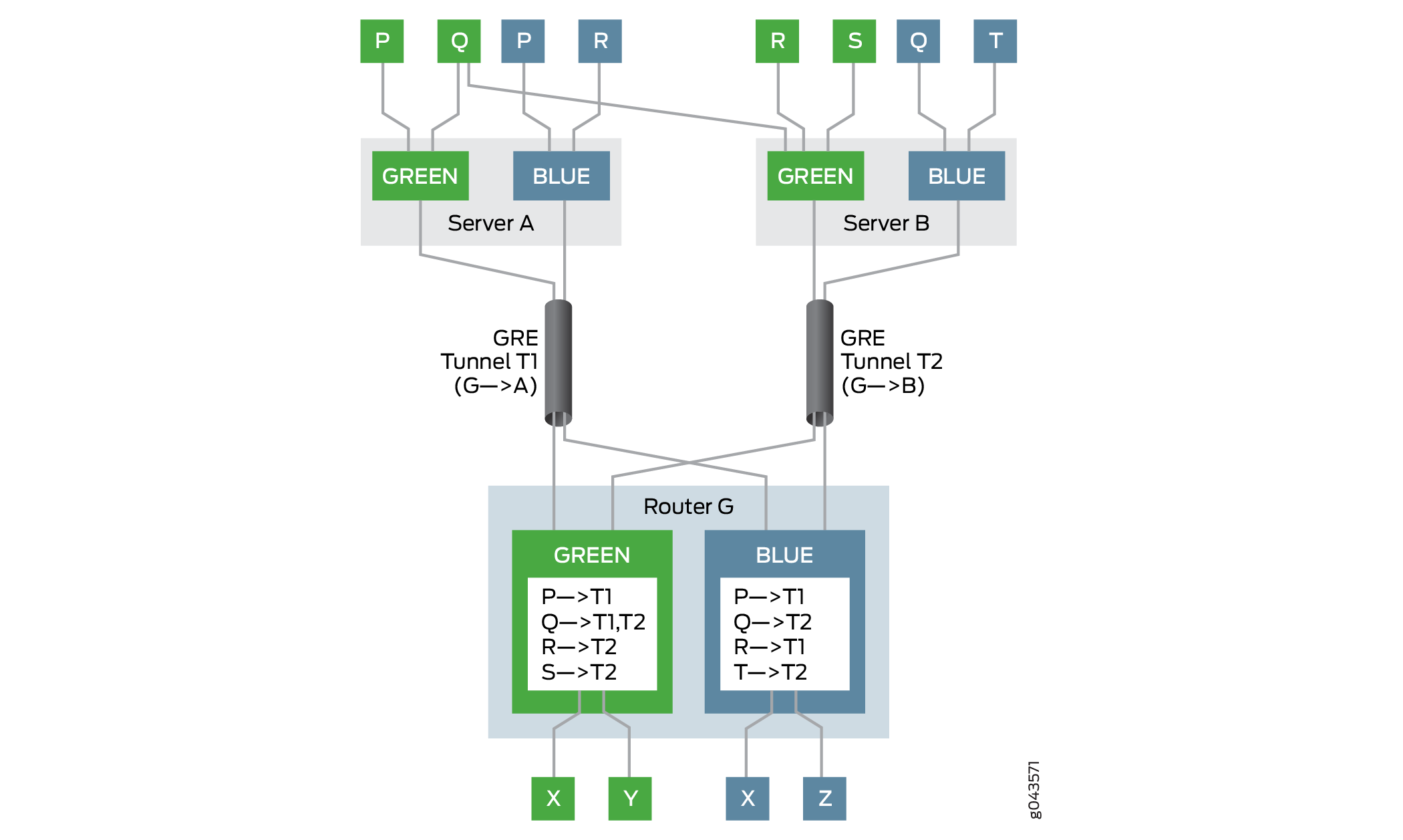
In this example, the gateway router is Router G. Router G has two VPNs—Green and Blue. The two servers, Server A and Server B, can reach the Green and Blue VPNs on Router G through the next-hop-based dynamic tunnels T1 and T2, respectively. Several hosts and virtual machines (P, Q, R, S, and T) connected to the servers can reach the VPNs through the gateway router, Router G. Router G has the virtual routing and forwarding (VRF) tables for Green and Blue VPNs, each populated with the reachability information for the virtual machines in those VPNs.
For example, in VPN Green, Router G uses tunnel T1 to reach host P, tunnel T2 to reach hosts R and S, and load balancing is done between tunnels T1 and T2 to reach the multihomed host Q. In VPN Blue, Router G uses tunnel T1 to reach hosts P and R, and tunnel T2 to reach hosts Q and T.
The check passes for reverse path forwarding when:
A packet comes from a legitimate source on its designated tunnel.
Host P in VPN Green sends a packet to host X using tunnel T1. Because Router G can reach host P through tunnel T1, it allows the packet to pass and forwards the packet to host X.
A packet comes from a multihomed source on its designated tunnels.
Host Q in VPN Green is multihomed on servers A and B, and can reach Router G through tunnels T1 and T2. Host Q sends a packet to host Y using tunnel T1, and a packet to host X using tunnel T2. Because Router G can reach host Q through tunnels T1 and T2, it allows the packets to pass and forwards them to hosts Y and X, respectively.
Layer 3 VPNs do not have anti-spoofing protection enabled by
default. To enable anti-spoofing for next-hop-based dynamic tunnels,
include the ip-tunnel-rpf-check statement at the [edit
routing-instances routing-instance-name routing-options
forwarding-table] hierarchy level. The reverse path forwarding
check is applied to the VRF routing instance only. The default mode
is set to strict, where the packet that comes from a source
on a nondesignated tunnel does not pass the check. The ip-tunnel-rpf-check mode can be set as loose, where the reverse path forwarding
check fails when the packet comes from a nonexistent source. An optional
firewall filter can be configured under the ip-tunnel-rpf-check statement to count and log the packets that failed the reverse path
forwarding check.
The following sample output shows an anti-spoofing configuration:
[edit
routing-instances routing-instance-name routing-options
forwarding-table]
ip-tunnel-rpf-check {
mode loose;
fail-filter filter-name;
}
Take the following guidelines under consideration when configuring anti-spoofing protection for next-hop-based dynamic tunnels:
Anti-spoofing protection can be enabled for IPv4 tunnels and IPv4 data traffic only. The anti-spoofing capabilities are not supported on IPv6 tunnels and IPv6 data traffic.
Anti-spoofing for next-hop-based dynamic tunnels can detect and prevent a compromised virtual machine (inner source reverse path forwarding check) but not a compromised server that is label-spoofing.
The next-hop-based IP tunnels can originate and terminate on an inet.0 routing table.
Anti-spoofing protection is effective when the VRF routing instance has label-switched interfaces (LSIs) (using the
vrf-table-label), or virtual tunnel (VT) interfaces. Withper-next-hoplabel on the VRF routing instance, anti-spoofing protection is not supported.The
rpf fail-filteris applicable only to the inner IP packet.Enabling anti-spoofing checks does not affect the scaling limit of the next-hop-based dynamic tunnels on a device.
The system resource utilization with anti-spoofing protection enabled for the VRF routing instance is slightly higher than the utilization of next-hop-based dynamic tunnels without the anti-spoofing protection enabled.
Anti-spoofing protection requires additional source IP address checks, which has minimal impact on network performance.
Graceful Routing Engine switchover (GRES) and in-service software upgrade (ISSU) are supported with anti-spoofing protection.
Example: Configuring Anti-Spoofing Protection for Next-Hop-Based Dynamic Tunnels
This example shows how to configure reverse path forwarding checks for the virtual routing and forwarding (VRF) routing instance to enable anti-spoofing protection for next-hop-based dynamic tunnels. The checks ensure that legitimate sources are injecting traffic through their designated IP tunnels.
Requirements
This example uses the following hardware and software components:
Three MX Series Routers with MICs, each connected to a host device.
Junos OS Release 17.1 or later running on one or all the routers.
Before you begin:
Enable tunnel services configuration on the Flexible PIC Concentrator.
Configure the router interfaces.
Configure the router-ID and assign an autonomous system number for the router.
Establish an internal BGP (IBGP) session with the tunnel endpoints.
Configure RSVP on all the routers.
Configure OSPF or any other interior gateway protocol on all the routers.
Configure two dynamic next-hop-based IP tunnels between the two routers.
Configure a VRF routing instance for every router-to-host connection.
Overview
Starting in Junos OS Release 17.1, anti-spoofing capabilities are added to next-hop-based dynamic IP tunnels, where checks are implemented for the traffic coming through the tunnel to the routing instance using reverse path forwarding in the Packet Forwarding Engine.
Currently, when the gateway router receives traffic from a tunnel, only the destination address lookup is done before forwarding. With anti-spoofing protection, the gateway router does a source address lookup of the encapsulation packet IP header in the VPN to ensure that legitimate sources are injecting traffic through their designated IP tunnels. This is called the strict mode and is the default behavior of anti-spoofing protection. To pass traffic from nondesignated tunnels, the reverse path forwarding check is enabled in the lose mode. For traffic received from nonexistent sources, the reverse path forwarding check fails for both the strict and loose modes.
Anti-spoofing is supported on VRF routing instances. To enable
anti-spoofing for dynamic tunnels, include the ip-tunnel-rpf-check statement at the [edit routing-instances routing-instance-name
routing-options forwarding-table] hierarchy level.
Topology
Figure 4 illustrates a sample network topology enabled with anti-spoofing protection. Routers R0, R1 and R2 are each connected to hosts Host0, Host1, and Host2, respectively. Two generic routing encapsulation (GRE) next-hop-based dynamic tunnels, Tunnel 1 and Tunnel 2 – connect Router R0 with Routers R1 and R2, respectively. The VRF routing instance is running between each router and its connected host devices.
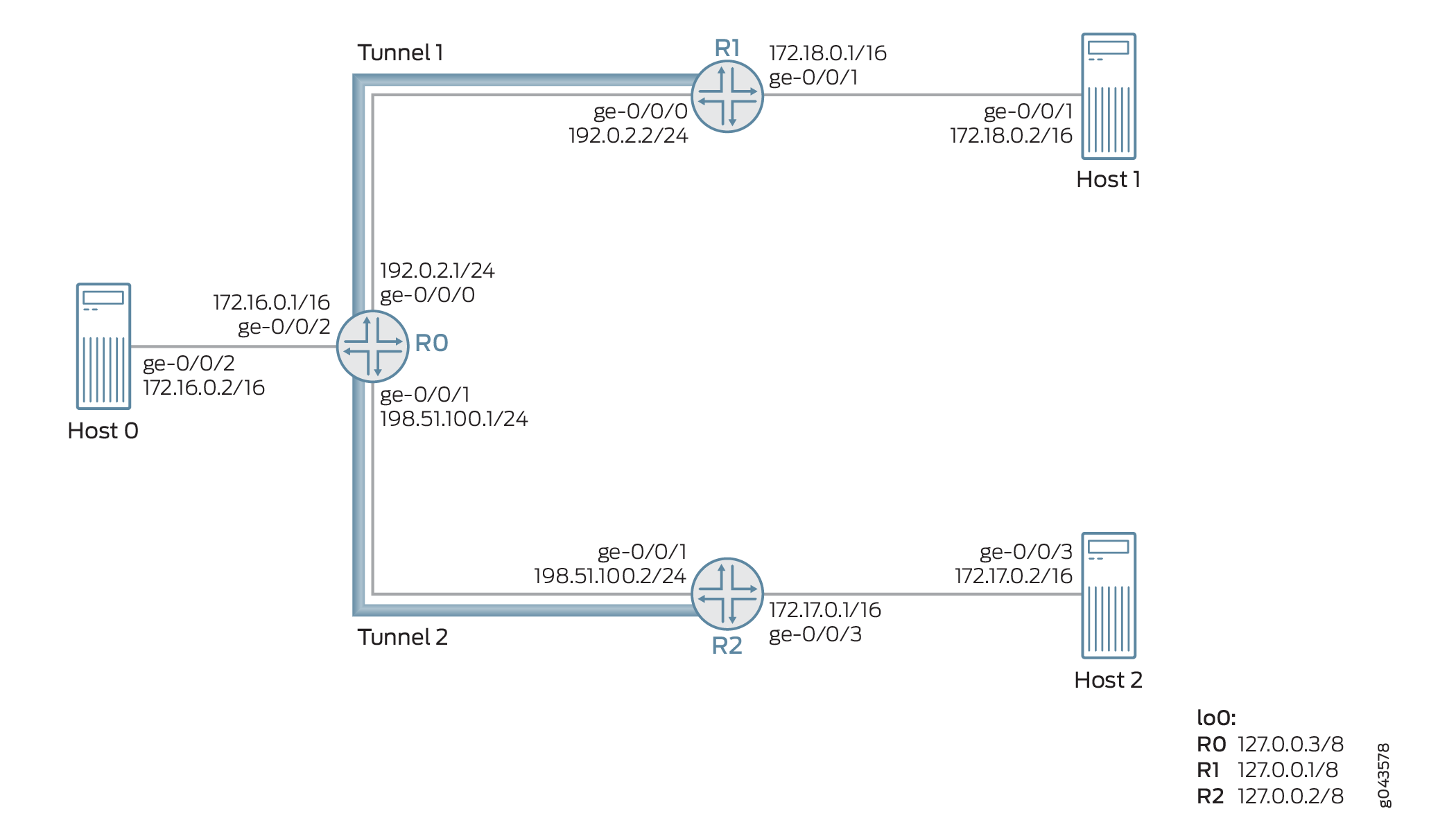
Taking as an example, three packets (Packets A, B, and C) are received on Router 0 from Router R2 through the next-hop-based dynamic GRE tunnel (Tunnel 2). The source IP address of these packets are 172.17.0.2 (Packet A), 172.18.0.2 (Packet B), and 172.20.0.2 (Packet C).
The source IP address of Packets A and B belong to Host 2 and Host 1, respectively. Packet C is a nonexistent source tunnel. The designated tunnel in this example is Tunnel 2, and the nondesignated tunnel is Tunnel 1. Therefore, the packets are processed as follows:
Packet A—Because the source is coming from a designated tunnel (Tunnel 2), Packet A passes the reverse path forwarding check and is processed for forwarding through Tunnel 2.
Packet B—Because the source is coming from Tunnel 1, which is a nondesinated tunnel, by default, Packet B fails the reverse path forwarding check in the strict mode. If loose mode is enabled, Packet B is allowed for forwarding.
Packet C—Because the source is a nonexistent tunnel source, Packet C fails the reverse path forwarding check, and the packet is not forwarded.
Configuration
CLI Quick Configuration
To quickly configure this example, copy the
following commands, paste them into a text file, remove any line breaks,
change any details necessary to match your network configuration,
copy and paste the commands into the CLI at the [edit] hierarchy
level, and then enter commit from configuration mode.
Router R0
set interfaces ge-0/0/0 unit 0 family inet address 192.0.2.1/24
set interfaces ge-0/0/1 unit 0 family inet address 198.51.100.1/24
set interfaces ge-0/0/2 vlan-tagging
set interfaces ge-0/0/2 unit 0 vlan-id 1
set interfaces ge-0/0/2 unit 0 family inet address 172.16.0.1/16
set interfaces lo0 unit 0 family inet address 10.1.1.1/32
set routing-options router-id 10.1.1.1
set routing-options autonomous-system 100
set routing-options dynamic-tunnels gre next-hop-based-tunnel
set routing-options dynamic-tunnels T1 source-address 192.0.2.1
set routing-options dynamic-tunnels T1 gre
set routing-options dynamic-tunnels T1 destination-networks 192.0.2.0/24
set routing-options dynamic-tunnels T2 source-address 198.51.100.1
set routing-options dynamic-tunnels T2 gre
set routing-options dynamic-tunnels T2 destination-networks 198.51.100.0/24
set protocols rsvp interface all
set protocols rsvp interface fxp0.0 disable
set protocols bgp group IBGP type internal
set protocols bgp group IBGP local-address 10.1.1.1
set protocols bgp group IBGP family inet-vpn unicast
set protocols bgp group IBGP neighbor 20.1.1.1
set protocols bgp group IBGP neighbor 30.1.1.1
set protocols ospf traffic-engineering
set protocols ospf area 0.0.0.0 interface lo0.0 passive
set protocols ospf area 0.0.0.0 interface all
set routing-instances VPN1 instance-type vrf
set routing-instances VPN1 interface ge-0/0/2.0
set routing-instances VPN1 route-distinguisher 100:100
set routing-instances VPN1 vrf-target target:100:1
set routing-instances VPN1 vrf-table-label
set routing-instances VPN1 routing-options forwarding-table ip-tunnel-rpf-check mode strict
set routing-instances VPN1 protocols bgp group External type external
set routing-instances VPN1 protocols bgp group External family inet unicast
set routing-instances VPN1 protocols bgp group External peer-as 200
set routing-instances VPN1 protocols bgp group External neighbor 172.16.0.1
Router R1
set interfaces ge-0/0/0 unit 0 family inet address 192.0.2.2/24
set interfaces ge-0/0/1 vlan-tagging
set interfaces ge-0/0/1 unit 0 vlan-id 2
set interfaces ge-0/0/1 unit 0 family inet address 172.18.0.1/16
set interfaces lo0 unit 0 family inet address 20.1.1.1/32
set routing-options router-id 20.1.1.1
set routing-options autonomous-system 100
set routing-options dynamic-tunnels gre next-hop-based-tunnel
set routing-options dynamic-tunnels T1 source-address 192.0.2.2
set routing-options dynamic-tunnels T1 gre
set routing-options dynamic-tunnels T1 destination-networks 192.0.2.0/24
set protocols rsvp interface all
set protocols rsvp interface fxp0.0 disable
set protocols bgp group IBGP type internal
set protocols bgp group IBGP local-address 20.1.1.1
set protocols bgp group IBGP family inet-vpn unicast
set protocols bgp group IBGP neighbor 30.1.1.1
set protocols bgp group IBGP neighbor 10.1.1.1
set protocols ospf traffic-engineering
set protocols ospf area 0.0.0.0 interface lo0.0 passive
set protocols ospf area 0.0.0.0 interface all
set routing-instances VPN2 instance-type vrf
set routing-instances VPN2 interface ge-0/0/1.0
set routing-instances VPN2 route-distinguisher 100:200
set routing-instances VPN2 vrf-target target:200:1
set routing-instances VPN2 vrf-table-label
R2
set interfaces ge-0/0/1 unit 0 family inet address 198.51.100.2/24
set interfaces ge-0/0/2 vlan-tagging
set interfaces ge-0/0/2 unit 0 vlan-id 3
set interfaces ge-0/0/2 unit 0 family inet address 172.17.0.1/16
set interfaces lo0 unit 0 family inet address 30.1.1.1/32
set routing-options router-id 30.1.1.1
set routing-options autonomous-system 100
set routing-options dynamic-tunnels gre next-hop-based-tunnel
set routing-options dynamic-tunnels T2 source-address 198.51.100.2
set routing-options dynamic-tunnels T2 gre
set routing-options dynamic-tunnels T2 destination-networks 198.51.100.0/24
set protocols rsvp interface all
set protocols rsvp interface fxp0.0 disable
set protocols bgp group IBGP type internal
set protocols bgp group IBGP local-address 30.1.1.1
set protocols bgp group IBGP family inet-vpn unicast
set protocols bgp group IBGP neighbor 20.1.1.1
set protocols bgp group IBGP neighbor 10.1.1.1
set protocols ospf traffic-engineering
set protocols ospf area 0.0.0.0 interface lo0.0 passive
set protocols ospf area 0.0.0.0 interface all
set routing-instances VPN3 instance-type vrf
set routing-instances VPN3 interface ge-0/0/2.0
set routing-instances VPN3 route-distinguisher 100:300
set routing-instances VPN3 vrf-target target:300:1
set routing-instances VPN3 vrf-table-label
Procedure
Step-by-Step Procedure
The following example requires that you navigate various levels in the configuration hierarchy. For information about navigating the CLI, see Using the CLI Editor in Configuration Mode in the CLI User Guide.
To configure Router R0:
Configure Router R0’s interfaces, including the loopback interface.
[edit interfaces]
user@R0# set ge-0/0/0 unit 0 family inet address 192.0.2.1/24
user@R0# set ge-0/0/1 unit 0 family inet address 198.51.100.1/24
user@R0# set ge-0/0/2 vlan-tagging
user@R0# set ge-0/0/2 unit 0 vlan-id 1
user@R0# set ge-0/0/2 unit 0 family inet address 172.16.0.1/16
user@R0# set lo0 unit 0 family inet address 10.1.1.1/32
Assign the router ID and autonomous system number for Router R0.
[edit routing-options]
user@R0# set router-id 10.1.1.1
user@R0# set autonomous-system 100
Configure IBGP peering between the routers.
[edit protocols]
user@R0# set bgp group IBGP type internal
user@R0# set bgp group IBGP local-address 10.1.1.1
user@R0# set bgp group IBGP family inet-vpn unicast
user@R0# set bgp group IBGP neighbor 20.1.1.1
user@R0# set bgp group IBGP neighbor 30.1.1.1
Configure OSPF on all the interfaces of Router R0, excluding the management interface.
[edit protocols]
user@R0# set ospf traffic-engineering
user@R0# set ospf area 0.0.0.0 interface lo0.0 passive
user@R0# set ospf area 0.0.0.0 interface all
Configure RSVP on all the interfaces of Router R0, excluding the management interface.
[edit protocols]
user@R0# set rsvp interface all
user@R0# set rsvp interface fxp0.0 disable
Enable next-hop-based dynamic GRE tunnel configuration on Router R0.
[edit routing-options]
user@R0# set dynamic-tunnels gre next-hop-based-tunnel
Configure the dynamic GRE tunnel parameters from Router R0 to Router R1.
[edit routing-options]
user@R0# set dynamic-tunnels T1 source-address 192.0.2.1
user@R0# set dynamic-tunnels T1 gre
user@R0# set dynamic-tunnels T1 destination-networks 192.0.2.0/24
Configure the dynamic GRE tunnel parameters from Router R0 to Router R2.
[edit routing-options]
user@R0# set dynamic-tunnels T2 source-address 198.51.100.1
user@R0# set dynamic-tunnels T2 gre
user@R0# set dynamic-tunnels T2 destination-networks 198.51.100.0/24
Configure a virtual routing and forwarding (VRF) routing instance on Router R0, and assign the interface connecting to Host 1 to the VRF instance.
[edit routing-instances]
user@R0# set VPN1 instance-type vrf
user@R0# set VPN1 route-distinguisher 100:100
user@R0# set VPN1 vrf-target target:100:1
user@R0# set VPN1 vrf-table-label
user@R0# set VPN1 interface ge-0/0/2.0
Configure an external BGP session with Host 1 for the VRF routing instance.
[edit routing-instances]
user@R0# set VPN1 protocols bgp group External type external
user@R0# set VPN1 protocols bgp group External family inet unicast
user@R0# set VPN1 protocols bgp group External peer-as 200
user@R0# set VPN1 protocols bgp group External neighbor 172.16.0.1
Configure anti-spoofing protection for the VRF routing instance on Router R0. This enables reverse path forwarding check for the next-hop-based dynamic tunnels, T1 and T2, on Router 0.
[edit routing-instances]
user@R0# set VPN1 routing-options forwarding-table ip-tunnel-rpf-check mode strict
Results
From configuration mode, confirm your configuration
by entering the show interfaces, show routing-options, show protocols, and show routing-options commands.
If the output does not display the intended configuration, repeat
the instructions in this example to correct the configuration.
user@R0# show interfaces
ge-0/0/0 {
    unit 0 {
        family inet {
            address 192.0.2.1/24;
        }
    }
}
ge-0/0/1 {
    unit 0 {
        family inet {
            address 198.51.100.1/24;
        }
    }
}
ge-0/0/2 {
    vlan-tagging;
    unit 0 {
        vlan-id 1;
        family inet {
            address 172.16.0.1/16;
        }
    }
}
lo0 {
    unit 0 {
        family inet {
            address 10.1.1.1/32;
        }
    }
}
user@R0# show routing-options
router-id 10.1.1.1;
autonomous-system 100;
dynamic-tunnels {
    gre next-hop-based-tunnel;
    T1 {
        source-address 192.0.2.1;
        gre;
        destination-networks {
            192.0.2.0/24;
        }
    }
    T2 {
        source-address 198.51.100.1;
        gre;
        destination-networks {
            198.51.100.0/24;
        }
    }
}
user@R0# show protocols
rsvp {
    interface all;
    interface fxp0.0 {
        disable;
    }
}
bgp {
    group IBGP {
        type internal;
        local-address 10.1.1.1;
        family inet-vpn {
            unicast;
        }
        neighbor 20.1.1.1;
        neighbor 30.1.1.1;
    }
}
ospf {
    traffic-engineering;
    area 0.0.0.0 {
        interface lo0.0 {
            passive;
        }
        interface all;
    }
}
user@R0# show routing-instances
VPN1 {
    instance-type vrf;
    interface ge-0/0/2.0;
    route-distinguisher 100:100;
    vrf-target target:100:1;
    vrf-table-label;
    routing-options {
        forwarding-table {
            ip-tunnel-rpf-check {
                mode strict;
            }
        }
    }
    protocols {
        bgp {
            group External {
                type external;
                family inet {
                    unicast;
                }
                peer-as 200;
                neighbor 172.16.0.1;
            }
        }
    }
}
Verification
Confirm that the configuration is working properly.
- Verifying Basic Configuration
- Verifying Dynamic Tunnel Configuration
- Verifying Anti-Spoofing Protection Configuration
Verifying Basic Configuration
Purpose
Verify the OSPF and BGP peering status between the Router R0 and Routers R1 and R2.
Action
From operational mode, run the show ospf neighbor and show bgp summarycommands.
user@R0> show ospf neighbor
Address          Interface              State     ID               Pri  Dead
192.0.2.2        ge-0/0/0.0             Full      20.1.1.1         128    32
198.51.100.2     ge-0/0/1.0             Full      30.1.1.1         128    32

user@R0> show bgp summary
Groups: 2 Peers: 3 Down peers: 1
Table          Tot Paths  Act Paths Suppressed    History Damp State    Pending
bgp.l3vpn.0
                       0          0          0          0          0          0
Peer                     AS      InPkt     OutPkt    OutQ   Flaps Last Up/Dwn State|#Active/Received/Accepted/Damped...
20.1.1.1                100        182        178       0       0     1:20:27 Establ
  bgp.l3vpn.0: 0/0/0/0
30.1.1.1                100        230        225       0       0     1:41:51 Establ
  bgp.l3vpn.0: 0/0/0/0
172.16.0.1              200          0          0       0       0     1:42:08 Establ
Meaning
The OSPF and BGP sessions are up and running between the Routers R0, R1, and R2.
Verifying Dynamic Tunnel Configuration
Purpose
Verify the status of the next-hop-based dynamic GRE tunnels between the Router R0 and Routers R1 and R2.
Action
From operational mode, run the show route table inet.3, and the show dynamic-tunnels database terse commands.
user@R0> show route table inet.3

inet.3: 2 destinations, 2 routes (2 active, 0 holddown, 0 hidden)
+ = Active Route, - = Last Active, * = Both

192.0.2.0/24       *[Tunnel/300] 01:47:57
                      Tunnel
192.0.2.2/24       *[Tunnel/300] 01:47:57
                      Tunnel Composite

198.51.100.0/24    *[Tunnel/300] 01:47:57
                      Tunnel
198.51.100.2/24    *[Tunnel/300] 01:47:57
Tunnel Compositeuser@R0> show dynamic-tunnels database terse Table: inet.3 Destination-network: 192.0.2.0/24 Destination Source Next-hop Type Status 192.0.2.2/24 192.0.2.1 0xb395e70 nhid 612 gre Up Destination-network: 198.51.100.0/24 Destination Source Next-hop Type Status 198.51.100.2 198.51.100.1 0xb395e70 nhid 612 gre Up
Meaning
The two next-hop-based dynamic GRE tunnels, Tunnel 1 and Tunnel 2, are up.
Verifying Anti-Spoofing Protection Configuration
Purpose
Verify that the reverse path forwarding check has been enabled on the VRF routing instance on Router R0.
Action
From the operational mode, run the show krt table VPN1.inet.0 detail.
user@R0> show krt table VPN1.inet.0 detail
KRT tables:
VPN1.inet.0                   : GF: 1 krt-index: 8     ID: 0 kernel-id: 8
        flags: (null)
        tunnel rpf config data : enable, strict, filter [0], 0x2
        tunnel rpf tlv data : enable, strict, filter [0], 0x4
        unicast reverse path: disabled
        fast-reroute-priority: 0
        Permanent NextHops
          Multicast        : 0 Broadcast : 0
          Receive          : 0   Discard   : 0
          Multicast Discard: 0   Reject    : 0
          Local            : 0   Deny      : 0
          Table            : 0
Meaning
The configured reverse path forwarding check is enabled on the VRF routing instance in the strict mode.
Change History Table
Feature support is determined by the platform and release you are using. Use Feature Explorer to determine if a feature is supported on your platform.