Interprovider VPNs
Interprovider VPNs
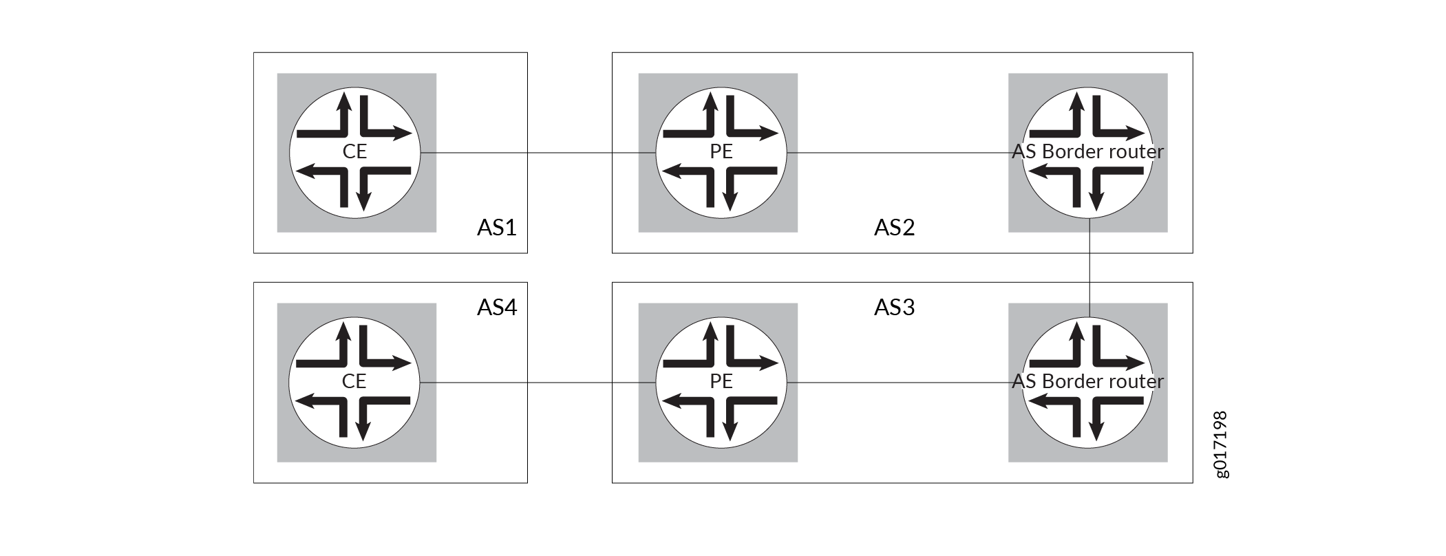
Interprovider VPNs provide connectivity between separate ASs. This functionality might be used by a VPN customer who has connections to several different service providers, or different connections to the same service provider in different geographic regions, each of which has a different AS. Figure 1 illustrates the type of network topology used by an interprovider VPN.
The following sections describe the ways you can configure an interprovider VPN:
- Linking VRF Tables Between Autonomous Systems
- Configuring Next Generation Layer 3 VPNs Options A, B, and C
- Configuring Multihop MP-EBGP Between AS Border Routers
Linking VRF Tables Between Autonomous Systems
You can connect two separate ASs by simply linking the VPN routing and forwarding (VRF) table in the AS border router (ASBR) of one AS to the VRF table in the ASBR in the other AS. Each ASBR must include a VRF routing instance for each VPN configured in both service provider networks. You then configure an IP session between the two ASBRs. In effect, the ASBRs treat each other as customer edge (CE) routers.
Because of the complexity of the configuration, particularly with regard to scaling, this method is not recommended. The details of this configuration are not provided with documentation.
Configuring Next Generation Layer 3 VPNs Options A, B, and C
For next generation Layer 3 VPNs, the PE routers within an AS use multiprotocol external BGP (MP-EBGP) to distribute labeled VPN–Internet Protocol version 4 (IPv4) routes to an ASBR or to a route reflector of which the ASBR is a client. The ASBR uses multiprotocol external BGP (MP-EBGP) to distribute the labeled VPN-IPv4 routes to its peer ASBR in the neighboring AS. The peer ASBR then uses MP-IBGP to distribute labeled VPN-IPv4 routes to PE routers, or to a route reflector of which the PE routers are a client.
You can configure both unicast (Junos OS Release 9.5 and later) and multicast (Junos OS Release 12.1 and later) next generation Layer 3 VPNs across ASs. The Junos OS software supports next generation Layer 3 VPNs option A, option B, and option C:
Option A—This is simple though less scaleable interprovider VPN solution to the problem of providing VPN services to a customer that has different sites, not all of which can use the same service provider. In this implementation, the VPN routing and forwarding (VRF) table in the ASBR of one AS is linked to the VRF table in the ASBR in the other AS. Each ASBR must include a VRF instance for each VPN configured in both service provider networks. Then an IGP or BGP must be configured between the ASBRs.
Option B—For this interprovider VPN solution, the customer requires VPN services for different sites, yet the same service provider is not available for all of those sites. With option B, the ASBR routers keep all VPN-IPv4 routes in the routing information base (RIB), and the labels associated with the prefixes are kept in the forwarding information base (FIB). Because the RIB and FIB tables can take too much of the respective allocated memory, this solution is not very scalable for an interprovider VPN. If a transit service provider is used between service provider 1 and service provider 2, the transit service provider also has to keep all VPN-IPv4 routes in the RIB and the corresponding labels in the FIB. The ASBRs at the transit service provider have the same functionality as ASBRs at service provider 1 or service provider 2 in this solution. The PE routers within each AS use multiprotocol internal BGP (MP-IBGP) to distribute labeled VPN-IPv4 routes to an ASBR or to a route reflector of which the ASBR is a client. The ASBR uses MP-EBGP to distribute the labeled VPN-IPv4 routes to its peer ASBR router in the neighboring AS. The peer ASBR then uses MP-IBGP to distribute labeled VPN-IPv4 routes to PE routers, or to a route reflector of which the PE routers are a client.
Option C—For this interprovider VPN solution, the customer service provider depends on the VPN service provider to deliver a VPN transport service between the customer service provider’s points of presence (POPs) or regional networks. This functionality might be used by a VPN customer who has connections to several different service providers, or different connections to the same service provider in different geographic regions, each of which has a different AS number. For option C, only routes internal to the service provider networks are announced between ASBRs. This is achieved by using the
family inet labeled-unicaststatements in the IBGP and EBGP configuration on the PE routers. Labeled IPv4 (not VPN-IPv4) routes are exchanged by the ASBRs to support MPLS. An MP-EBGP session between the end PE routers is used for the announcement of VPN-IPv4 routes. In this manner, VPN connectivity is provided while keeping VPN-IPv4 routes out of the core network.
Configuring Multihop MP-EBGP Between AS Border Routers
In this type of interprovider VPN configuration, P routers do not need to store all the routes in all the VPNs. Only the PE routers must have all the VPN routes. The P routers simply forward traffic to the PE routers—they do not store or process any information about the packets’ destination. The connections between the AS border routers in separate ASs forward traffic between the ASs, much as a label-switched path (LSP) works.
The following are the basic steps you take to configure an interprovider VPN in this manner:
Configure multihop EBGP redistribution of labeled VPN-IPv4 routes between the source and destination ASs.
Configure EBGP to redistribute labeled IPv4 routes from its AS to neighboring ASs.
Configure MPLS on the end PE routers of the VPNs.
See Also
Example: Configuring Interprovider Layer 3 VPN Option A
Interprovider Layer 3 VPN Option A provides interprovider VRF-to-VRF connections at the AS boundary routers (ASBRs). Compared to Option B and Option C, Option A is the least scalable solution.
This example provides a step-by-step procedure to configure interprovider Layer 3 VPN option A, which is one of the recommended implementations of MPLS VPN when that service is required by a customer that has more than one AS and but not all of the customer’s ASs can be serviced by the same service provider. It is organized in the following sections:
Requirements
This example uses the following hardware and software components:
-
Junos OS Release 9.5 or later.
-
Eight M Series, T Series, TX Series, or MX Series Juniper Networks routers.
Overview and Topology
This is the simplest and least scalable interprovider VPN solution to the problem of providing VPN services to a customer that has different sites, not all of which can use the same service provider (SP).
RFC 4364, section 10, refers to this method as Interprovider VRF-to-VRF connections at the AS border routers.
In this configuration:
-
The virtual routing and forwarding (VRF) table in the ASBR of one AS is linked to the VRF table in the ASBR in the other AS. Each ASBR must contain a VRF instance for every VPN configured in both service provider networks. Then an IGP or BGP must be configured between the ASBRs. This has the disadvantage of limiting scalability.
-
In this configuration, the autonomous system boundary routers (ASBRs) at both SPs are configured as regular PE routers, and provide MPLS L3 VPN service to the neighbor SP.
-
Each PE router treats the other as if it were a customer edge (CE) router. ASBRs play the role of regular CE routers for the ASBR of the remote SP. ASBRs see each other as CE devices.
-
A provider edge (PE) router in one autonomous system (AS) attaches directly to a PE router in another AS.
-
The two PE routers are attached by multiple sub-interfaces, at least one for each of the VPNs whose routes need to be passed from AS to AS.
-
The PE routers associate each sub-interface with a VPN routing and forwarding (VRF) table, and use EBGP to distribute unlabeled IPv4 addresses to each other.
-
In this solution, all common VPNs defined at both PEs must also be defined at one or more ASBRs between the two SPs. This is not a very scalable methodology, especially when a transit SP is used by two regional SPs for interconnection.
-
This is a procedure that is simple to configure and it does not require MPLS at the border between ASs. Additionally, it does not scale as well as other recommended procedures.
The topology of the network is shown in Figure 2.
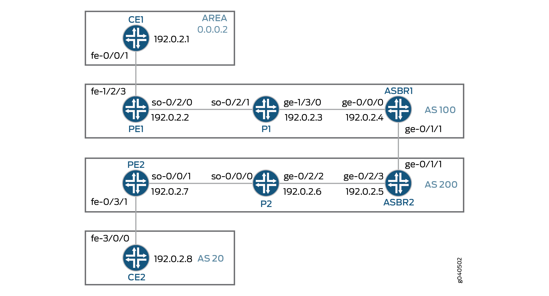
Topology
Configuration
The procedure presented here is written with the assumption that the reader is already familiar with MPLS MVPN configuration. This example focuses on explaining the unique configuration required for carrier-of-carriers solutions for VPN services to different sites.
To configure interprovider layer 3 VPN option A, perform the following tasks:
- Configuring Router CE1
- Configuring Router PE1
- Configuring Router P1
- Configuring Router ASBR1
- Configuring Router ASBR2
- Configuring Router P2
- Configuring Router PE2
- Configuring Router CE2
- Verifying the VPN Operation
Configuring Router CE1
Step-by-Step Procedure
-
On Router CE1, configure the IP address and protocol family on the Fast Ethernet interface for the link between Router CE1 and Router PE1. Specify the
inetaddress family type.[edit interfaces fe-0/0/1.0] family inet { address 198.51.100.1/24; } -
On Router CE1, configure the IP address and protocol family on the loopback interface. Specify the
inetaddress family type.[edit interfaces lo0] unit 0 { family inet { address 192.0.2.1/32; } } -
On Router CE1, configure a routing protocol. The routing protocol can be a static route, RIP, OSPF, IS-IS, or EBGP. In this example we configure OSPF. Include the Fast Ethernet interface for the link between Router CE1 and Router PE1 and the logical loopback interface of Router CE1.
[edit protocols]
ospf {
    area 0.0.0.2 {
        interface fe-0/0/1.0;
        interface lo0.0;
    }
}
Configuring Router PE1
Step-by-Step Procedure
-
On Router PE1, configure IPv4 addresses on the SONET, Fast Ethernet, and logical loopback interfaces. Specify the
inetaddress family on all of the interfaces. Specify themplsaddress family on the SONET and Fast Ethernet interfaces.[edit interfaces] so-0/2/0 { unit 0 { family inet { address 192.168.1.9/24; } family mpls; } } fe-1/2/3 { unit 0 { family inet { address 198.51.100.2/24; } family mpls; } } lo0 { unit 0 { family inet { address 192.0.2.2/32; } } } -
On Router PE1, configure the routing instance for VPN2. Specify the
vrfinstance type and specify the customer-facing Fast Ethernet interface. Configure a route distinguisher to create a unique VPN-IPv4 address prefix. Apply the VRF import and export policies to enable the sending and receiving of route targets. Configure the OSPF protocol within the VRF. Specify the customer-facing Fast Ethernet interface and specify the export policy to export BGP routes into OSPF.[edit routing-instances] vpn2CE1 { instance-type vrf; interface fe-1/2/3.0; route-distinguisher 1:100; vrf-import vpnimport; vrf-export vpnexport; protocols { ospf { export bgp-to-ospf; area 0.0.0.2 { interface fe-1/2/3.0; } } } } -
On Router PE1, configure the RSVP and MPLS protocols to support the label-switched path (LSP). Configure the LSP to Router ASBR1 and specify the IP address of the logical loopback interface on Router ASBR1. Configure a BGP group. Specify the group type as
internal. Specify the local address as the logical loopback interface on Router PE1. Specify the neighbor address as the logical loopback interface on Router ASBR1. Specify theinet-vpnaddress family andunicasttraffic type to enable BGP to carry IPv4 network layer reachability information (NLRI) for VPN routes. Configure the OSPF protocol. Specify the core-facing SONET interface and specify the logical loopback interface on Router PE1.[edit protocols] rsvp { interface so-0/2/0.0; interface lo0.0; } mpls { label-switched-path To-ASBR1 { to 192.0.2.4; } interface so-0/2/0.0; interface lo0.0; } bgp { group To_ASBR1 { type internal; local-address 192.0.2.2; neighbor 192.0.2.4 { family inet-vpn { unicast; } } } } ospf { traffic-engineering; area 0.0.0.0 { interface so-0/2/0.0; interface lo0.0; } } -
On Router PE1, configure the BGP local autonomous system number.
[edit routing-options]
autonomous-system 100;
-
On Router PE1, configure a policy to export the BGP routes into OSPF.
[edit policy-options] policy-statement bgp-to-ospf { term 1 { from protocol bgp; then accept; } term 2 { then reject; } } -
On Router PE1, configure a policy to add the VRF route target to the routes being advertised for this VPN.
[edit policy-options] policy-statement vpnexport { term 1 { from protocol ospf; then { community add test_comm; accept; } } term 2 { then reject; } } -
On Router PE1, configure a policy to import routes from BGP that have the
test_commcommunity attached.[edit policy-options] policy-statement vpnimport { term 1 { from { protocol bgp; community test_comm; } then accept; } term 2 { then reject; } } -
On Router PE1, define the
test_commBGP community with a route target.[edit policy-options] community test_comm members target:1:100;
Configuring Router P1
Step-by-Step Procedure
-
On Router P1, configure IP addresses for the SONET and Gigabit Ethernet interfaces. Enable the interfaces to process the
inetandmplsaddress families. Configure the IP address for thelo0.0loopback interface and enable the interface to process theinetaddress family.[edit interfaces] so-0/2/1 { unit 0 { family inet { address 192.168.1.4/24; } family mpls; } } ge-1/3/0 { unit 0 { family inet { address 192.168.2.5/24; } family mpls; } } lo0 { unit 0 { family inet { address 192.0.2.3/32; } } } -
On Router P1, configure the RSVP and MPLS protocols to support the LSP. Specify the SONET and Gigabit Ethernet interfaces.
Configure the OSPF protocol. Specify the SONET and Gigabit Ethernet interfaces and specify the logical loopback interface. Enable OSPF to support traffic engineering extensions.
[edit protocols]
rsvp {
    interface so-0/2/1.0;
    interface ge-1/3/0.0;
    interface lo0.0;
}
mpls {
    interface lo0.0;
    interface ge-1/3/0.0;
    interface so-0/2/1.0;
}
ospf {
    traffic-engineering;
    area 0.0.0.0 {
        interface ge-1/3/0.0;
        interface so-0/2/1.0;
        interface lo0.0;
    }
}
Configuring Router ASBR1
Step-by-Step Procedure
-
On Router ASBR1, configure IP addresses for the Gigabit Ethernet interfaces. Enable the interfaces to process the
inetandmplsaddresses families. Configure the IP addresses for thelo0.0loopback interface and enable the interface to process theinetaddress family.[edit interfaces] ge-0/0/0 { unit 0 { family inet { address 192.168.2.6/24; } family mpls; } } ge-0/1/1 { unit 0 { family inet { address 192.168.3.7/24; } family mpls; } } lo0 { unit 0 { family inet { address 192.0.2.4/32; } } } -
On Router ASBR1, configure the
To_ASBR2routing instance. Specify thevrfinstance type and specify the core-facing Gigabit Ethernet interface. Configure a route distinguisher to create a unique VPN-IPv4 address prefix. Configure a route target for the VPN. Configure the BGP peer group within the VRF. Specify AS 200 as the peer AS and specify the IP address of the Gigabit Ethernet interface on Router ASBR2 as the neighbor address.[edit routing instances] To_ASBR2{ instance-type vrf; interface ge-0/1/1.0; route-distinguisher 1:100; vrf-target target:1:100; protocols { bgp { group To_ASBR2 { type external; neighbor 192.168.3.8 { peer-as 200; } } } } } -
On Router ASBR1, configure the RSVP and MPLS protocols to support the LSP by specifying the Gigabit Ethernet interface that is facing the P1 router.
Configure the OSPF protocol by specifying the Gigabit Ethernet interface that is facing the P1 router and the logical loopback interface. Enable OSPF to support traffic engineering extensions.
[edit protocols] rsvp { interface ge-0/0/0.0; interface lo0.0; } mpls { label-switched-path To_PE1 { to 192.0.2.2; } interface lo0.0; interface ge-0/0/0.0; } ospf { traffic-engineering; area 0.0.0.0 { interface ge-0/0/0.0; interface lo0.0; } } -
On Router ASBR1, create the
To-PE1internal BGP peer group. Specify the local IP peer address as the locallo0.0address. Specify the neighbor IP peer address as thelo0.0interface address of Router PE1.[edit protocols] bgp { group To-PE1 { type internal; local-address 192.0.2.4; neighbor 192.0.2.2 { family inet-vpn { unicast; } } } } -
On Router ASBR1, configure the BGP local autonomous system number.
[edit routing-options]
autonomous-system 100;
Configuring Router ASBR2
Step-by-Step Procedure
-
On Router ASBR2, configure IP addresses for the Gigabit Ethernet interfaces. Enable the interfaces to process the
inetandmplsaddress families. Configure the IP address for thelo0.0loopback interface and enable the interface to process theinetaddress family.[edit interfaces] ge-0/1/1 { unit 0 { family inet { address 192.168.3.8/24; } family mpls; } } ge-0/2/3 { unit 0 { family inet { address 192.168.4.10/24; } family mpls; } } lo0 { unit 0 { family inet { address 192.0.2.5/32; } } } -
On Router ASBR2, configure the
To_ASBR1routing instance. Specify thevrfinstance type and specify the core-facing Gigabit Ethernet interface. Configure a route distinguisher to create a unique VPN-IPv4 address prefix. Configure a route target for the VPN. Configure the BGP peer group within the VRF. Specify AS 100 as the peer AS and specify the IP address of the Gigabit Ethernet interface on Router ASBR1 as the neighbor address.[edit routing-instances] To_ASBR1 { instance-type vrf; interface ge-0/1/1.0; route-distinguisher 1:100; vrf-target target:1:100; protocols { bgp { group To_ASBR1 { type external; neighbor 192.168.3.7 { peer-as 100; } } } } } -
On Router ASBR2, configure the RSVP and MPLS protocols to support the LSP by specifying the Gigabit Ethernet interface that is facing the P2 router.
Configure the OSPF protocol by specifying the Gigabit Ethernet interface that is facing the P2 router and the logical loopback interface. Enable OSPF to support traffic engineering extensions.
[edit protocols] rsvp { interface ge-0/2/3.0; interface lo0.0; } mpls { label-switched-path To_PE2 { to 192.0.2.7; } interface lo0.0; interface ge-0/2/3.0; } ospf { traffic-engineering; area 0.0.0.0 { interface ge-0/2/3.0; interface lo0.0; } } -
On Router ASBR2, create the
To-PE2internal BGP peer group. Specify the local IP peer address as the locallo0.0address. Specify the neighbor IP peer address as thelo0.0interface address of Router PE2.[edit protocols] bgp { group To-PE2 { type internal; local-address 192.0.2.5; neighbor 192.0.2.7 { family inet-vpn { unicast; } } } -
On Router ASBR2, configure the BGP local autonomous system number.
[edit routing-options]
autonomous-system 200;
Configuring Router P2
Step-by-Step Procedure
-
On Router P2, configure IP addresses for the SONET and Gigabit Ethernet interfaces. Enable the interfaces to process the
inetandmplsaddress families. Configure the IP address for thelo0.0loopback interface and enable the interface to process theinetaddress family.[edit interfaces] so-0/0/0 { unit 0 { family inet { address 192.168.5.11/24; } family mpls; } } ge-0/2/2 { unit 0 { family inet { address 192.168.4.12/24; } family mpls; } } lo0 { unit 0 { family inet { address 192.0.2.6/32; } } } -
On Router P2, configure the RSVP and MPLS protocols to support the LSP. Specify the SONET and Gigabit Ethernet interfaces.
Configure the OSPF protocol. Specify the SONET and Gigabit Ethernet interfaces and specify the logical loopback interface. Enable OSPF to support traffic engineering extensions.
[edit protocols]
rsvp {
    interface so-0/0/0.0;
    interface ge-0/2/2.0;
    interface lo0.0;
}
mpls {
    interface lo0.0;
    interface ge-0/2/2.0;
    interface so-0/0/0.0;
}
ospf {
    traffic-engineering;
    area 0.0.0.0 {
        interface ge-0/2/2.0;
        interface so-0/0/0.0;
        interface lo0.0;
    }
}
Configuring Router PE2
Step-by-Step Procedure
-
On Router PE2, configure IPv4 addresses on the SONET, Fast Ethernet, and logical loopback interfaces. Specify the
inetaddress family on all of the interfaces. Specify themplsaddress family on the SONET and Fast Ethernet interfaces.[edit interfaces] so-0/0/1 { unit 0 { family inet { address 192.168.5.12/24; } family mpls; } } fe-0/3/1 { unit 0 { family inet { address 192.168.6.13/24; } family mpls; } lo0 { unit 0 { family inet { address 192.0.2.7/32; } } } -
On Router PE2, configure the routing instance for VPN2. Specify the
vrfinstance type and specify the customer-facing Fast Ethernet interface. Configure a route distinguisher to create a unique VPN-IPv4 address prefix. Apply the VRF import and export policies to enable the sending and receiving of route targets. Configure the BGP peer group within the VRF. Specify AS20as the peer AS and specify the IP address of the Fast Ethernet interface on Router CE2 as the neighbor address.[edit routing-instances] vpn2CE2 { instance-type vrf; interface fe-0/3/1.0; route-distinguisher 1:100; vrf-import vpnimport; vrf-export vpnexport; protocols { bgp { group To_CE2 { peer-as 20; neighbor 192.168.6.14; } } } } -
On Router PE2, configure the RSVP and MPLS protocols to support the LSP. Configure the LSP to ASBR2 and specify the IP address of the logical loopback interface on Router ASBR2. Configure a BGP group. Specify the group type as
internal. Specify the local address as the logical loopback interface on Router PE2. Specify the neighbor address as the logical loopback interface on the Router ASBR2. Specify theinet-vpnaddress family andunicasttraffic type to enable BGP to carry IPv4 NLRI for VPN routes. Configure the OSPF protocol. Specify the core-facing SONET interface and specify the logical loopback interface on Router PE2.[edit protocols] rsvp { interface so-0/0/1.0; interface lo0.0; } mpls { label-switched-path To-ASBR2 { to 192.0.2.5; } interface so-0/0/1.0; interface lo0.0; } bgp { group To_ASBR2 { type internal; local-address 192.0.2.7; neighbor 192.0.2.5 { family inet-vpn { unicast; } } } } ospf { traffic-engineering; area 0.0.0.0 { interface so-0/0/1.0; interface lo0.0; } } -
On Router PE2, configure the BGP local autonomous system number.
[edit routing-options]
autonomous-system 200;
-
On Router PE2, configure a policy to add the VRF route target to the routes being advertised for this VPN.
[edit policy-options] policy-statement vpnexport { term 1 { from protocol bgp; then { community add test_comm; accept; } } term 2 { then reject; } } -
On Router PE2, configure a policy to import routes from BGP that have the
test_commcommunity attached.[edit policy-options] policy-statement vpnimport { term 1 { from { protocol bgp; community test_comm; } then accept; } term 2 { then reject; } } -
On Router PE2, define the
test_commBGP community with a route target.[edit policy-options] community test_comm members target:1:100;
Configuring Router CE2
Step-by-Step Procedure
-
On Router CE2, configure the IP address and protocol family on the Fast Ethernet interface for the link between Router CE2 and Router PE2. Specify the
inetaddress family type.[edit interfaces] fe-3/0/0 { unit 0 { family inet { address 192.168.6.14/24; } } } -
On Router CE2, configure the IP address and protocol family on the loopback interface. Specify the
inetaddress family type.[edit interfaces lo0] lo0 { unit 0 { family inet { address 192.0.2.8/32; } } } -
On Router CE2, define a policy named
myroutesthat accepts direct routes.[edit policy-options] policy-statement myroutes { from protocol direct; then accept; } -
On Router CE2, configure a routing protocol. The routing protocol can be a static route, RIP, OSPF, IS-IS, or EBGP. In this example, we configure EBGP. Specify AS
200as the peer AS and specify the BGP neighbor IP address as the Fast Ethernet interface of Router PE2.[edit protocols] bgp { group To_PE2 { neighbor 192.168.6.13 { export myroutes; peer-as 200; } } } -
On Router CE2, configure the BGP local autonomous system number.
[edit routing-options]
autonomous-system 20;
Verifying the VPN Operation
Step-by-Step Procedure
-
Commit the configuration on each router.
Note:The MPLS labels shown in this example will be different than the labels used in your configuration.
-
On Router PE1, display the routes for the
vpn2CE1routing instance using theshow ospf routecommand. Verify that the192.0.2.1route is learned from OSPF.user@PE1> show ospf route instance vpn2CE1 Topology default Route Table: Prefix Path Route NH Metric NextHop Nexthop Type Type Type Interface addr/label 192.0.2.1 Intra Router IP 1 fe-1/2/3.0 198.51.100.1 192.0.2.1/32 Intra Network IP 1 fe-1/2/3.0 198.51.100.1 198.51.100.0/24 Intra Network IP 1 fe-1/2/3.0 198.51.100.1 -
On Router PE1, use the
show route advertising-protocolcommand to verify that Router PE1 advertises the192.0.2.1route to Router ASBR1 using MP-BGP with the VPN MPLS label.user@PE1> show route advertising-protocol bgp 192.0.2.4 extensive vpn2CE1.inet.0: 6 destinations, 6 routes (6 active, 0 holddown, 0 hidden) * 192.0.2.1/32 (1 entry, 1 announced) BGP group To_PE1 type Internal Route Distinguisher: 1:100 VPN Label: 299856 Nexthop: Self Flags: Nexthop Change MED: 1 Localpref: 100 AS path: [100] I Communities: target:1:100 rte-type:0.0.0.2:1:0 -
On Router ASBR1, use the
show route receive-protocolcommand to verify that the router receives and accepts the192.0.2.1route and places it in theTo_ASBR2.inet.0routing table.user@ASBR1> show route receive-protocol bgp 192.0.2.2 extensive inet.0: 7 destinations, 7 routes (7 active, 0 holddown, 0 hidden) inet.3: 1 destinations, 1 routes (1 active, 0 holddown, 0 hidden) To_ASBR2.inet.0: 4 destinations, 4 routes (4 active, 0 holddown, 0 hidden) * 192.0.2.1/32 (1 entry, 1 announced) Route Distinguisher: 1:100 VPN Label: 299856 Nexthop: 192.0.2.2 MED: 1 Localpref: 100 AS path: I Communities: target:1:100 rte-type:0.0.0.2:1:0 MPLS.0: 4 destinations, 4 routes (4 active, 0 holddown, 0 hidden) BGP.13VPN.0: 1 destinations, 1 routes (1 active, 0 holddown, 0 hidden) * 1:100:192.0.2.1/32 (1 entry, 0 announced) Route Distinguisher: 1:100 VPN Label: 299856 Nexthop: 192.0.2.2 MED: 1 Localpref: 100 AS path: I Communities: target:1:100 rte-type:0.0.0.2:1:0 -
On Router ASBR1, use the
show route advertising-protocolcommand to verify that Router ASBR1 advertises the192.0.2.1route to Router ASBR2.user@ASBR1> show route advertising-protocol bgp 192.168.3.8 extensive To_ASBR2.inet.0: 4 destinations, 4 routes (4 active, 0 holddown, 0 hidden) * 192.0.2.1/32 (1 entry, 1 announced) BGP group To_ASBR2.inet.0 type External Nexthop: Self AS path: [100] I Communities: target:1:100 rte-type:0.0.0.2:1:0 -
On Router ASBR2, use the
show route receive-protocolcommand to verify that the router receives and accepts the192.0.2.1route and places it in theTo_ASBR1.inet.0routing table.user@ASBR2> show route receive-protocol bgp 192.168.3.7 extensive inet.0: 7 destinations, 7 routes (7 active, 0 holddown, 0 hidden) inet.3: 1 destinations, 1 routes (1 active, 0 holddown, 0 hidden) To_ASBR1.inet.0: 4 destinations, 4 routes (4 active, 0 holddown, 0 hidden) * 192.0.2.1/32 (1 entry, 1 announced) Accepted Nexthop: 192.168.3.7 AS path: 100 I Communities: target:1:100 rte-type:0.0.0.2:1:0 MPLS.0: 4 destinations, 4 routes (4 active, 0 holddown, 0 hidden) BGP.l3VPN.0: 1 destinations, 1 routes (1 active, 0 holddown, 0 hidden) -
On Router ASBR2, use the
show route advertising-protocolcommand to verify that Router ASBR2 advertises the192.0.2.1route to Router PE2.user@ASBR2> show route advertising-protocol bgp 192.0.2.7 extensive To_ASBR1.inet.0: 4 destinations, 4 routes (4 active, 0 holddown, 0 hidden) * 192.0.2.1/32 (1 entry, 1 announced) BGP group To-PE2 type Internal Route Distinguisher: 1:100 VPN Label: 299936 Nexthop: Self Flags: Nexthop Change Localpref: 100 AS path: [200] 100 I Communities: target:1:100 rte-type:0.0.0.2:1:0 -
On Router PE2, use the
show route receive-protocolcommand to verify that the router receives and accepts the192.0.2.1route and places it in thevpn2CE2.inet.0routing table.user@PE2> show route receive-protocol bgp 192.0.2.5 extensive inet.0: 12 destinations, 13 routes (12 active, 0 holddown, 0 hidden) inet.3: 1 destinations, 1 routes (1 active, 0 holddown, 0 hidden) __juniper_private1__.inet.0: 14 destinations, 14 routes (8 active, 0 holddown, 6 hidden) __juniper_private2__.inet.0: 1 destinations, 1 routes (0 active, 0 holddown, 1 hidden) vpn2CE2.inet.0: 5 destinations, 6 routes (5 active, 0 holddown, 0 hidden) * 192.0.2.1/32 (1 entry, 1 announced) Accepted Route Distinguisher: 1:100 VPN Label: 299936 Nexthop: 192.0.2.5 Localpref: 100 AS path: 100 I AS path: Recorded Communities: target:1:100 rte-type:0.0.0.2:1:0 -
On Router PE2, use the
show route advertising-protocolcommand to verify that Router PE2 advertises the192.0.2.1route to Router CE2 through theTo_CE2peer group.user@PE2> show route advertising-protocol bgp 192.168.6.14 extensive vpn2CE2.0: 5 destinations, 6 routes (5 active, 0 holddown, 0 hidden) * 192.0.2.1/32 (1 entry, 1 announced) BGP group To_CE2 type External Nexthop: Self AS path: [200] 100 I Communities: target:1:100 rte-type:0.0.0.2:1:0 -
On Router CE2, use the
show routecommand to verify that Router CE2 receives the192.0.2.1route from Router PE2.user@CE2> show route 192.0.2.1 inet.0: 6 destinations, 6 routes (6 active, 0 holddown, 0 hidden) + = Active Route, - = Last Active, * = Both 192.0.2.1/32 *[BGP/170] 00:25:36, localpref 100 AS path: 200 100 I > to 192.168.6.13 via fe-3/0/0.0 -
On Router CE2, use the
pingcommand and specify192.0.2.8as the source of the ping packets to verify connectivity with Router CE1.user@CE2> ping 192.0.2.1 source 192.0.2.8 PING 192.0.2.1 (192.0.2.1): 56 data bytes 64 bytes from 192.0.2.1: icmp_seq=0 ttl=58 time=4.672 ms 64 bytes from 192.0.2.1: icmp_seq=1 ttl=58 time=10.480 ms 64 bytes from 192.0.2.1: icmp_seq=2 ttl=58 time=10.560 ms
-
On Router PE2, use the
show routecommand to verify that the traffic is sent with an inner label of299936and a top label of299776.user@PE2> show route 192.0.2.1 detail vpn2CE2.inet.0: 5 destinations, 6 routes (5 active, 0 holddown, 0 hidden) 192.0.2.1/32 (1 entry, 1 announced) *BGP Preference: 170/-101 Route Distinguisher: 1:100 Next hop type: Indirect Next-hop reference count: 6 Source: 192.0.2.5 Next hop type: Router, Next hop index: 648 Next hop: via so-0/0/1.0 weight 0x1, selected Label-switched-path To-ASBR2 Label operation: Push 299936, Push 299776(top) Protocol next hop: 192.0.2.5 Push 299984 Indirect next hop: 8c6109c 262143 State: <Secondary Active Int Ext> Local AS: 200 Peer AS: 200 Age: 3:37 Metric2: 2 Task: BGP_200.192.0.2.5+179 Announcement bits (3): 0-RT 1-KRT 2-BGP RT Background AS path: 100 I AS path: Recorded Communities: target:1:100 rte-type:0.0.0.2:1:0 Accepted VPN Label: 299984 Localpref: 100 Router ID: 192.0.2.5 Primary Routing Table BGP.l3VPN.0 -
On Router ASBR2, use the
show route tablecommand to verify that Router ASBR2 receives the traffic.user@ASBR2# show route table mpls.0 detail 299936 (1 entry, 1 announced) *VPN Preference: 170 Next hop type: Router, Next hop index: 649 Next-hop reference count: 2 Source: 192.168.3.7 Next hop: 192.168.3.7 via ge-0/1/1.0, selected Label operation: Pop State: <Active Int Ext> Local AS: 200 Age: 9:54 Task: BGP RT Background Announcement bits (1): 0-KRT AS path: 100 I Ref Cnt: 1 Communities: target:1:100 rte-type:0.0.0.2:1:0 -
On Router ASBR2, use the
show route tablecommand to verify that Router ASBR2 receives the traffic.user@ASBR2# show route 192.0.2.1 detail To_ASBR1.inet.0: 4 destinations, 4 routes (4 active, 0 holddown, 0 hidden) 192.0.2.1/32 (1 entry, 1 announced) *BGP Preference: 170/-101 Next hop type: Router, Next hop index: 576 Next-hop reference count: 3 Source: 192.168.3.7 Next hop: 192.168.3.7 via ge-0/1/1.0, selected State: <Active Ext> Peer AS: 100 Age: 13:07 Task: BGP_192.168.3.7+53372 Announcement bits (2): 0-KRT 1-BGP RT Background AS path: 100 I Communities: target:1:100 rte-type:0.0.0.2:1:0 Accepted Localpref: 100 Router ID: 192.168.3.7 -
On Router ASBR1, use the
show routecommand to verify that ASBR1 sends traffic toward PE1 with the top label299792and VPN label299856.user@ASBR1# show route 192.0.2.1 detail To_ASBR2.inet.0: 4 destinations, 4 routes (4 active, 0 holddown, 0 hidden) 192.0.2.1/24 (1 entry, 1 announced) *BGP Preference: 170/-101 Route Distinguisher: 1:100 Next hop type: Indirect Next-hop reference count: 3 Source: 192.0.2.2 Next hop type: Router, Next hop index: 669 Next hop: 192.168.2.5 via ge-0/0/0.0 weight 0x1, selected Label-switched-path To_PE1 Label operation: Push 299856, Push 299792(top) Protocol next hop: 192.0.2.2 Push 299856 Indirect next hop: 8af70a0 262143 State: <Secondary Active Int Ext> Local AS: 100 Peer AS: 100 Age: 12:15 Metric: 1 Metric2: 2 Task: BGP_100.192.0.2.2+58065 Announcement bits (2): 0-KRT 1-BGP RT Background AS path: I Communities: target:1:100 rte-type:0.0.0.2:1:0 VPN Label: 299856 Localpref: 100 Router ID: 192.0.2.2 Primary Routing Table BGP.l3VPN.0 -
On Router PE1, use the
show route tablecommand to verify that Router PE1 receives the traffic with label299856, pops the label,l and the traffic is sent toward Router CE1 through interfacefe-1/2/3.0.lab@PE1# show route table mpls.0 detail 299856 (1 entry, 1 announced) *VPN Preference: 170 Next hop type: Router, Next hop index: 666 Next-hop reference count: 2 Next hop: 198.51.100.8 via fe-1/2/3.0, selected Label operation: Pop State: <Active Int Ext> Local AS: 100 Age: 17:38 Task: BGP RT Background Announcement bits (1): 0-KRT AS path: I Ref Cnt: 1 Communities: rte-type:0.0.0.2:1:0 -
On Router PE1, use the
show routecommand to verify that PE1 receives the traffic after the top label is popped by Router P and the traffic is sent toward Router CE1 through interfacefe-1/2/3.0.lab@PE1# show route 192.0.2.1 detail vpn2CE1.inet.0: 6 destinations, 6 routes (6 active, 0 holddown, 0 hidden) 192.0.2.1/32 (1 entry, 1 announced) *OSPF Preference: 10 Next hop type: Router, Next hop index: 634 Next-hop reference count: 3 Next hop: 198.51.100.8 via fe-1/2/3.0, selected State: <Active Int> Age: 18:42 Metric: 1 Area: 0.0.0.2 Task: VPN2alice-OSPFv2 Announcement bits (2): 2-KRT 3-BGP RT Background AS path: I Communities: rte-type:0.0.0.2:1:0
Example: Configuring Interprovider Layer 3 VPN Option B
Interprovider Layer 3 VPN Option B provides interprovider EBGP redistribution of labeled VPN-IPv4 routes from AS to neighboring AS. This solution is considered to be more scalable than Option A, but not as scalable as Option C.
This example provides a step-by-step procedure to configure interprovider layer 3 VPN option B, which is one of the recommended implementations of an MPLS VPN for a customer that has more than one AS, but not all of the customer’s ASs can be serviced by the same service provider. It is organized in the following sections:
Requirements
This example uses the following hardware and software components:
Junos OS Release 9.5 or later.
- This example has been recently updated and revalidated on Junos OS Release 21.1R1.
Eight M Series, T Series, TX Series, QFX10000, or MX Series Juniper Networks routers.
Configuration Overview and Topology
Interprovider layer 3 VPN option B is a somewhat scalable solution to the problem of providing VPN services to a customer that has different sites, not all of which can use the same service provider. RFC 4364, section 10, refers to this method as interprovider EBGP redistribution of labeled VPN-IPv4 routes from AS to neighboring AS.
In the topology shown in Figure 1, the following events occur:
The PE routers use IBGP to redistribute labeled VPN-IPv4 routes to an ASBR.
The ASBR then uses EBGP to redistribute those labeled VPN-IPv4 routes to an ASBR in another AS, which distributes them to the PE routers in that AS.
Labeled VPN-IPv4 routes are distributed between ASBR routers on each site. There is no need to define a separate VPN routing and forwarding instance (VRF) for each common VPN that resides on two different SPs.
Router PE2 distributes VPN-IPv4 routes to Router ASBR2 using MP-IBGP.
Router ASBR2 distributes these labeled VPN-IPv4 routes to Router ASBR1, using the MP-EBGP session between them.
Router ASBR1 redistributes those routes to Router PE1, using MP-IBGP. Each time a label is advertised, routers change the next-hop information and labels.
An MPLS path is established between Router PE1 and Router PE2. This path enables changing of the next-hop attribute for the routes that are learned from the neighbor SP router and map the incoming label for the given routes to the outgoing label advertised to PE routers in the internal network.
The ingress PE router inserts two labels onto the IP packet coming from the end customer. The inner label is for the VPN-IPv4 routes learned from internal ASBRs and the outer label is for the route to the internal ASBR, obtained through resource reservation protocol (RSVP) or label distribution protocol (LDP).
When a packet arrives at the ASBR, it removes the outer label (when explicit-null signaling is used; otherwise, penultimate hop-popping (PHP) pops the label) and swaps the inner label with the label obtained from the neighbor ASBR through MP-EBGP label and prefix advertisements.
The second ASBR swaps the VPN-IPv4 label and pushes another label to reach the PE router in its own AS.
The remaining process is the same as for a regular VPN.
In this solution, ASBR routers keep all VPN-IPv4 routes in the routing information base (RIB), and the labels associated with the prefixes are kept in the forwarding information base (FIB). Because the RIB and FIB tables can take occupy much of the respective allocated memory, this solution is not very scalable for an interprovider VPN.
If a transit SP is used between SP1 and SP2, the transit SP also has to keep all VPN-IPv4 routes in the RIB and the corresponding labels in the FIB. The ASBRs at the transit SP have the same functionality as ASBRs in the SP1 or SP2 networks in this solution.
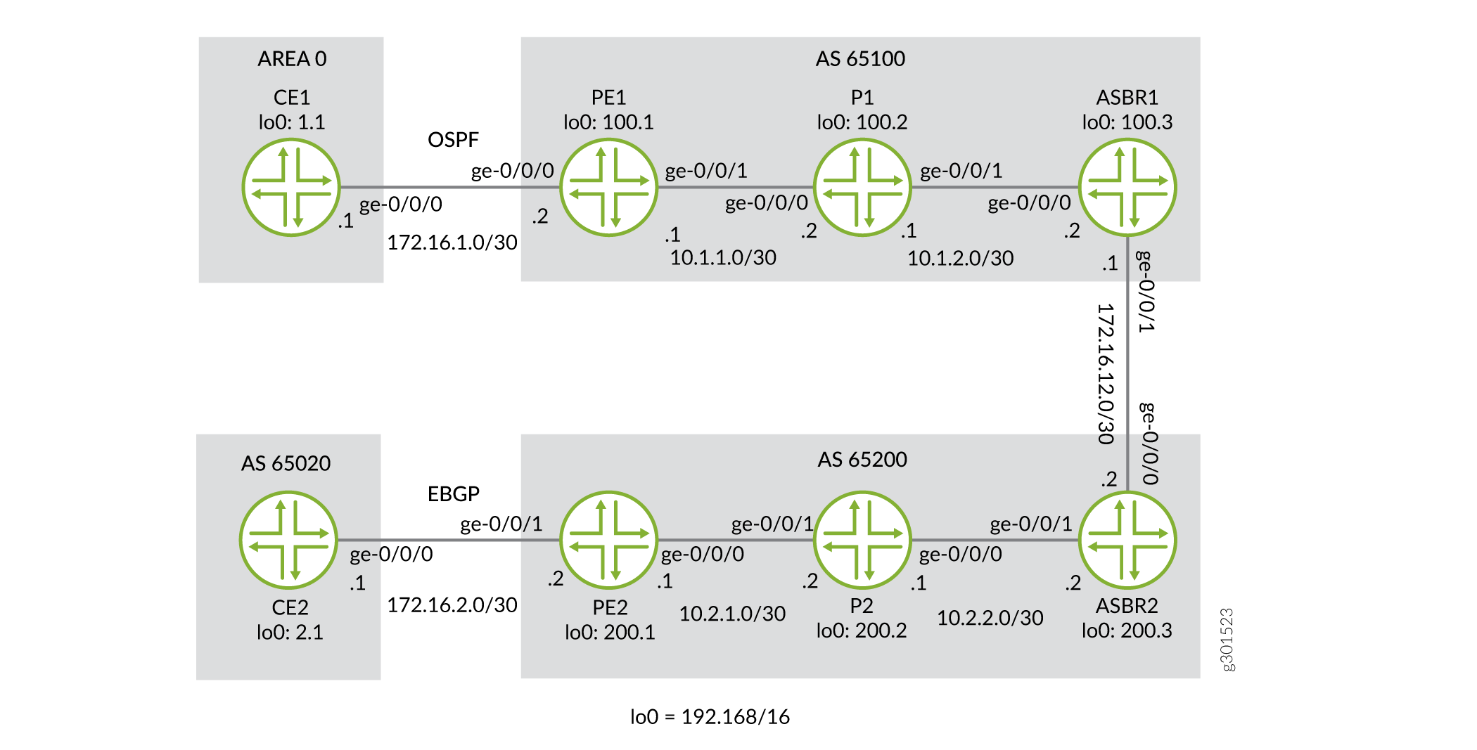
Topology
The topology of the network is shown in Figure 3.
Configuration
The procedure presented here is written with the assumption that the reader is already familiar with MPLS MVPN configuration. This example focuses on explaining the unique configuration required for carrier-of-carriers solutions for VPN services to different sites.
To configure layer 3 VPN option B, perform the following tasks:
- Configuring Router CE1
- Configuring Router PE1
- Configuring Router P1
- Configuring Router ASBR1
- Configuring Router ASBR2
- Configuring Router P2
- Configuring Router PE2
- Configuring Router CE2
- Verifying the VPN Operation
Configuring Router CE1
Step-by-Step Procedure
On Router CE1, configure the IP address and protocol family on the logical loopback interface and the Gigabit Ethernet interface for the link between Router CE1 and Router PE1. Specify the
inetaddress family type.user@CE1# set interfaces ge-0/0/0 description to_PE1 set interfaces ge-0/0/0 unit 0 family inet address 172.16.1.1/30 set interfaces lo0 unit 0 family inet address 192.168.1.1/32
On Router CE1, configure the router ID.
user@CE1#
set routing-options router-id 192.168.1.1
On Router CE1, configure a routing protocol. Include the logical interface for the link between Router CE1 and Router PE1 and the logical loopback interface of Router CE1. The routing protocol can be a static route, RIP, OSPF, IS-IS, or EBGP. In this example we configure OSPF.
user@CE1#
set protocols ospf area 0.0.0.0 interface ge-0/0/0.0
set protocols ospf area 0.0.0.0 interface lo0.0
Configuring Router PE1
Step-by-Step Procedure
On Router PE1, configure IPv4 addresses on the Gigabit Ethernet and logical loopback interfaces. Specify the
inetaddress family on all of the interfaces. Specify themplsaddress family on the core-facing interface.user@PE1# set interfaces ge-0/0/0 description to_CE1 set interfaces ge-0/0/0 unit 0 family inet address 172.16.1.2/30 set interfaces ge-0/0/1 description to_P1 set interfaces ge-0/0/1 unit 0 family inet address 10.1.1.1/30 set interfaces ge-0/0/1 unit 0 family mpls set interfaces lo0 unit 0 family inet address 192.168.100.1/32
On Router PE1, configure a VRF routing instance. Specify the
vrfinstance type and specify the customer-facing interface. Configure a route distinguisher to create a unique VPN-IPv4 address prefix. Apply the VRF import and export policies to enable the sending and receiving of route targets. Configure the OSPF protocol within the VRF. Specify the customer-facing interface and specify the export policy to export BGP routes into OSPF.user@PE1# set routing-instances to_CE1 instance-type vrf set routing-instances to_CE1 protocols ospf area 0.0.0.0 interface ge-0/0/0.0 set routing-instances to_CE1 protocols ospf export bgp-to-ospf set routing-instances to_CE1 interface ge-0/0/0.0 set routing-instances to_CE1 route-distinguisher 192.168.100.1:1 set routing-instances to_CE1 vrf-import vpnimport set routing-instances to_CE1 vrf-export vpnexport
On Router PE1, configure the RSVP and MPLS protocols to support the label-switched path (LSP). Configure the LSP to Router ASBR1 and specify the IP address of the logical loopback interface on Router ASBR1. Configure a BGP group. Specify the group type as
internal. Specify the local address as the logical loopback interface on Router PE1. Specify the neighbor address as the logical loopback interface on Router ASBR1. Specify theinet-vpnaddress family andunicasttraffic type to enable BGP to carry IPv4 network layer reachability information (NLRI) for VPN routes. Configure the OSPF protocol. Specify the core-facing interface and specify the logical loopback interface on Router PE1.user@PE1# set protocols bgp group to-ASBR1 type internal set protocols bgp group to-ASBR1 local-address 192.168.100.1 set protocols bgp group to-ASBR1 neighbor 192.168.100.3 family inet-vpn unicast set protocols mpls label-switched-path to-ASBR1 to 192.168.100.3 set protocols mpls interface ge-0/0/1.0 set protocols mpls interface lo0.0 set protocols ospf traffic-engineering set protocols ospf area 0.0.0.0 interface ge-0/0/1.0 set protocols ospf area 0.0.0.0 interface lo0.0 set protocols rsvp interface ge-0/0/1.0 set protocols rsvp interface lo0.0
On Router PE1, configure the BGP local autonomous system number and router ID.
user@PE1#
set routing-options router-id 192.168.100.1
set routing-options autonomous-system 65100
On Router PE1, configure a policy to export the BGP routes into OSPF.
user@PE1#
set policy-options policy-statement bgp-to-ospf term 1 from protocol bgp
set policy-options policy-statement bgp-to-ospf term 1 then accept
set policy-options policy-statement bgp-to-ospf term 2 then reject
On Router PE1, configure a policy to add the VRF route target to the routes being advertised from CE1.
user@PE1#
set policy-options policy-statement vpnexport term 1 from protocol ospf
set policy-options policy-statement vpnexport term 1 then community add pe1_comm
set policy-options policy-statement vpnexport term 1 then accept
set policy-options policy-statement vpnexport term 2 then reject
On Router PE1, configure a policy to import routes from PE2 that have the
pe2_commcommunity attached.user@PE1# set policy-options policy-statement vpnimport term 1 from protocol bgp set policy-options policy-statement vpnimport term 1 from community pe2_comm set policy-options policy-statement vpnimport term 1 then accept set policy-options policy-statement vpnimport term 2 then reject
On Router PE1, define the
pe1_commBGP community with a route target to apply to the vpnexport policy and define thepe2_commBGP community with a route target to apply to the vpnimport policy.user@PE1# set policy-options community pe1_comm members target:65100:1 set policy-options community pe2_comm members target:65200:1
Configuring Router P1
Step-by-Step Procedure
On Router P1, configure IP addresses for the Gigabit Ethernet interfaces. Enable the interfaces to process the
inetandmplsaddress families. Configure the IP addresses for thelo0.0loopback interface and enable the interface to process theinetaddress family.user@P1# set interfaces ge-0/0/0 description to_PE1 set interfaces ge-0/0/0 unit 0 family inet address 10.1.1.2/30 set interfaces ge-0/0/0 unit 0 family mpls set interfaces ge-0/0/1 description to_ASBR1 set interfaces ge-0/0/1 unit 0 family inet address 10.1.2.1/30 set interfaces ge-0/0/1 unit 0 family mpls set interfaces lo0 unit 0 family inet address 192.168.100.2/32
On Router P1, configure the RSVP and MPLS protocols to support the LSP. Specify the Gigabit Ethernet interfaces.
Configure the OSPF protocol. Specify the Gigabit Ethernet interfaces and specify the logical loopback interface. Enable OSPF to support traffic engineering extensions.
user@P1#
set protocols mpls interface ge-0/0/0.0
set protocols mpls interface ge-0/0/1.0
set protocols mpls interface lo0.0
set protocols ospf traffic-engineering
set protocols ospf area 0.0.0.0 interface ge-0/0/0.0
set protocols ospf area 0.0.0.0 interface ge-0/0/1.0
set protocols ospf area 0.0.0.0 interface lo0.0
set protocols rsvp interface ge-0/0/0.0
set protocols rsvp interface ge-0/0/1.0
set protocols rsvp interface lo0.0
Configuring Router ASBR1
Step-by-Step Procedure
On Router ASBR1, configure IP addresses for the Gigabit Ethernet interfaces. Enable the interfaces to process the
inetandmplsaddresses families. Configure the IP addresses for thelo0.0loopback interface and enable the interface to process theinetaddress family.user@ASBR1# set interfaces ge-0/0/0 description to_P1 set interfaces ge-0/0/0 unit 0 family inet address 10.1.2.2/30 set interfaces ge-0/0/0 unit 0 family mpls set interfaces ge-0/0/1 description to_ASBR2 set interfaces ge-0/0/1 unit 0 family inet address 172.16.12.1/30 set interfaces ge-0/0/1 unit 0 family mpls set interfaces lo0 unit 0 family inet address 192.168.100.3/32
On Router ASBR1, configure the RSVP and MPLS protocols to support the LSP by specifying the Gigabit Ethernet interface facing the P1 router and the
lo0.0logical loopback interface.Configure the OSPF protocol by specifying the Gigabit Ethernet interface that is facing the P1 router and the logical loopback interface. Enable OSPF to support traffic engineering extensions.
user@ASBR1#
set protocols mpls label-switched-path to-PE1 to 192.168.100.1
set protocols mpls interface ge-0/0/0.0
set protocols mpls interface lo0.0
set protocols ospf traffic-engineering
set protocols ospf area 0.0.0.0 interface ge-0/0/0.0
set protocols ospf area 0.0.0.0 interface lo0.0
set protocols rsvp interface ge-0/0/0.0
set protocols rsvp interface lo0.0
On Router ASBR1, create the
to-PE1internal BGP peer group. Specify the local IP peer address as the locallo0.0address. Specify the neighbor IP peer address as thelo0.0interface address of Router PE1.user@ASBR1# set protocols bgp group to-PE1 type internal set protocols bgp group to-PE1 local-address 192.168.100.3 set protocols bgp group to-PE1 neighbor 192.168.100.1 family inet-vpn unicast
On Router ASBR1, create the
to-ASBR2external BGP peer group. Enable the router to use BGP to advertise NLRI for unicast routes. Specify the neighbor IP peer address as the Gigabit Ethernet interface address of Router ASBR2.user@ASBR1# set protocols bgp group to-ASBR2 type external set protocols bgp group to-ASBR2 family inet-vpn unicast set protocols bgp group to-ASBR2 neighbor 172.16.12.2 peer-as 65200
On Router ASBR1, configure the BGP local autonomous system number the router ID.
user@ASBR1#
set routing-options router-id 192.168.100.3
set routing-options autonomous-system 65100
Configuring Router ASBR2
Step-by-Step Procedure
On Router ASBR2, configure IP addresses for the Gigabit Ethernet interfaces. Enable the interfaces to process the
inetandmplsaddress families. Configure the IP address for thelo0.0loopback interface and enable the interface to process theinetaddress family.user@ASBR2# set interfaces ge-0/0/0 description to_ASBR1 set interfaces ge-0/0/0 unit 0 family inet address 172.16.12.2/30 set interfaces ge-0/0/0 unit 0 family mpls set interfaces ge-0/0/1 description to_P2 set interfaces ge-0/0/1 unit 0 family inet address 10.2.2.2/30 set interfaces ge-0/0/1 unit 0 family mpls set interfaces lo0 unit 0 family inet address 192.168.200.3/32
On Router ASBR2, configure the RSVP and MPLS protocols to support the LSP by specifying the Gigabit Ethernet interface that is facing the P2 router.
Configure the OSPF protocol by specifying the Gigabit Ethernet interface that is facing the P2 router and the logical loopback interface. Enable OSPF to support traffic engineering extensions.
user@ASBR2#
set protocols mpls label-switched-path to-PE2 to 192.168.200.1
set protocols mpls interface ge-0/0/1.0
set protocols mpls interface lo0.0
set protocols ospf traffic-engineering
set protocols ospf area 0.0.0.0 interface ge-0/0/1.0
set protocols ospf area 0.0.0.0 interface lo0.0
set protocols rsvp interface ge-0/0/1.0
set protocols rsvp interface lo0.0
On Router ASBR2, create the
to-PE2internal BGP peer group. Specify the local IP peer address as the locallo0.0address. Specify the neighbor IP peer address as thelo0.0interface address of Router PE2.user@ASBR2# set protocols bgp group to-PE2 type internal set protocols bgp group to-PE2 local-address 192.168.200.3 set protocols bgp group to-PE2 neighbor 192.168.200.1 family inet-vpn unicast
On Router ASBR2, create the
to-ASBR1external BGP peer group. Enable the router to use BGP to advertise NLRI for unicast routes. Specify the neighbor IP peer address as the Gigabit Ethernet interface on Router ASBR1.user@ASBR2# set protocols bgp group to-ASBR1 type external set protocols bgp group to-ASBR1 family inet-vpn unicast set protocols bgp group to-ASBR1 neighbor 172.16.12.1 peer-as 65100
On Router ASBR2, configure the BGP local autonomous system number and the router ID.
user@ASBR2#
set routing-options router-id 192.168.200.3
set routing-options autonomous-system 65200
Configuring Router P2
Step-by-Step Procedure
On Router P2, configure IP addresses for the Gigabit Ethernet interfaces. Enable the interfaces to process the
inetandmplsaddress families. Configure the IP address for thelo0.0loopback interface and enable the interface to process theinetaddress family.user@P2# set interfaces ge-0/0/0 description to_ASBR2 set interfaces ge-0/0/0 unit 0 family inet address 10.2.2.1/30 set interfaces ge-0/0/0 unit 0 family mpls set interfaces ge-0/0/1 description to_PE2 set interfaces ge-0/0/1 unit 0 family inet address 10.2.1.2/30 set interfaces ge-0/0/1 unit 0 family mpls set interfaces lo0 unit 0 family inet address 192.168.200.2/32
On Router P2, configure the RSVP and MPLS protocols to support the LSP. Specify the Gigabit Ethernet interfaces.
Configure the OSPF protocol. Specify the Gigabit Ethernet interfaces and specify the logical loopback interface. Enable OSPF to support traffic engineering extensions.
user@P2#
set protocols mpls interface ge-0/0/0.0
set protocols mpls interface ge-0/0/1.0
set protocols mpls interface lo0.0
set protocols ospf traffic-engineering
set protocols ospf area 0.0.0.0 interface ge-0/0/0.0
set protocols ospf area 0.0.0.0 interface ge-0/0/1.0
set protocols ospf area 0.0.0.0 interface lo0.0
set protocols rsvp interface ge-0/0/0.0
set protocols rsvp interface ge-0/0/1.0
set protocols rsvp interface lo0.0
Configuring Router PE2
Step-by-Step Procedure
On Router PE2, configure IPv4 addresses on the Gigabit Ethernet and logical loopback interfaces. Specify the
inetaddress family on all of the interfaces. Specify themplsaddress family on the Gigabit Ethernet interfaces.user@PE2# set interfaces ge-0/0/0 description to_P2 set interfaces ge-0/0/0 unit 0 family inet address 10.2.1.1/30 set interfaces ge-0/0/0 unit 0 family mpls set interfaces ge-0/0/1 description to_CE2 set interfaces ge-0/0/1 unit 0 family inet address 172.16.2.2/30 set interfaces lo0 unit 0 family inet address 192.168.200.1/32
On Router PE2, configure a VRF routing instance. Specify the
vrfinstance type and specify the customer-facing interface. Configure a route distinguisher to create a unique VPN-IPv4 address prefix. Apply the VRF import and export policies to enable the sending and receiving of route targets. Configure the BGP peer group within the VRF. Specify AS65020as the peer AS and specify the IP address of the Gigabit Ethernet interface on Router CE1 as the neighbor address.user@PE2# set routing-instances to_CE2 instance-type vrf set routing-instances to_CE2 protocols bgp group to_CE2 type external set routing-instances to_CE2 protocols bgp group to_CE2 peer-as 65020 set routing-instances to_CE2 protocols bgp group to_CE2 neighbor 172.16.2.1 set routing-instances to_CE2 interface ge-0/0/1.0 set routing-instances to_CE2 route-distinguisher 192.168.200.1:1 set routing-instances to_CE2 vrf-import vpnimport set routing-instances to_CE2 vrf-export vpnexport
On Router PE2, configure the RSVP and MPLS protocols to support the LSP. Configure the LSP to ASBR2 and specify the IP address of the logical loopback interface on Router ASBR2. Configure a BGP group. Specify the group type as
internal. Specify the local address as the logical loopback interface on Router PE2. Specify the neighbor address as the logical loopback interface on the Router ASBR2. Specify theinet-vpnaddress family andunicasttraffic type to enable BGP to carry IPv4 NLRI for VPN routes. Configure the OSPF protocol. Specify the core-facing interface and the logical loopback interface on Router PE2.user@PE2# set protocols bgp group to-ASBR2 type internal set protocols bgp group to-ASBR2 local-address 192.168.200.1 set protocols bgp group to-ASBR2 neighbor 192.168.200.3 family inet-vpn unicast set protocols mpls label-switched-path to-ASBR2 to 192.168.200.3 set protocols mpls interface ge-0/0/0.0 set protocols mpls interface lo0.0 set protocols ospf traffic-engineering set protocols ospf area 0.0.0.0 interface ge-0/0/0.0 set protocols ospf area 0.0.0.0 interface lo0.0 set protocols rsvp interface ge-0/0/0.0 set protocols rsvp interface lo0.0
On Router PE2, configure the BGP local autonomous system number and the router ID.
user@PE2#
set routing-options router-id 192.168.200.1
set routing-options autonomous-system 65200
On Router PE2, configure a policy to add the VRF route target to the routes being advertised from CE2.
user@PE2#
set policy-options policy-statement vpnexport term 1 from protocol bgp
set policy-options policy-statement vpnexport term 1 then community add pe2_comm
set policy-options policy-statement vpnexport term 1 then accept
set policy-options policy-statement vpnexport term 2 then reject
On Router PE2, configure a policy to import routes from PE1 that have the
pe1_commcommunity attached.user@PE2# set policy-options policy-statement vpnimport term 1 from protocol bgp set policy-options policy-statement vpnimport term 1 from community pe1_comm set policy-options policy-statement vpnimport term 1 then accept set policy-options policy-statement vpnimport term 2 then reject
On Router PE2, define the
pe2_commBGP community with a route target to apply to the vpnexport policy and define thepe1_commBGP community with a route target to apply to the vpnimport policyuser@PE2# set policy-options community pe1_comm members target:65100:1 set policy-options community pe2_comm members target:65200:1
Configuring Router CE2
Step-by-Step Procedure
On Router CE2, configure the IP address and protocol family on the logical loopback interface and the Gigabit Ethernet interface for the link between Router CE2 and Router PE2. Specify the
inetaddress family type.user@CE2# set interfaces ge-0/0/0 description to_PE2 set interfaces ge-0/0/0 unit 0 family inet address 172.16.2.1/30 set interfaces lo0 unit 0 family inet address 192.168.2.1/32
On Router CE2, define a policy named
loopbackthat matches on the loopback address for CE2.user@CE2# set policy-options policy-statement loopback term 1 from route-filter 192.168.2.1/32 exact set policy-options policy-statement loopback term 1 then accept
On Router CE2, configure a routing protocol. The routing protocol can be a static route, RIP, OSPF, IS-IS, or EBGP. In this example, we configure EBGP. Specify AS
65200as the peer AS and specify the BGP neighbor IP address as the Gigabit Ethernet interface of Router PE2. Include theexportstatement.user@CE2# set protocols bgp group to_PE2 export loopback set protocols bgp group to_PE2 peer-as 65200 set protocols bgp group to_PE2 neighbor 172.16.2.2
On Router CE2, configure the BGP local autonomous system number and the router ID.
user@CE2#
set routing-options router-id 192.168.2.1
set routing-options autonomous-system 65020
Verifying the VPN Operation
Step-by-Step Procedure
Commit the configuration on each router.
Note:The MPLS labels shown in this example will be different than the labels used in your configuration.
On Router PE1, display the routes for the
to_CE1routing instance using theshow ospf routecommand. Verify that the192.168.1.1route is learned from OSPF.user@PE1> show ospf route instance to_CE1 Topology default Route Table: Prefix Path Route NH Metric NextHop Nexthop Type Type Type Interface Address/LSP 192.168.1.1 Intra Router IP 1 ge-0/0/0.0 172.16.1.1 172.16.1.0/30 Intra Network IP 1 ge-0/0/0.0 192.168.1.1/32 Intra Network IP 1 ge-0/0/0.0 172.16.1.1On Router PE1, use the
show route advertising-protocolcommand to verify that Router PE1 advertises the192.168.1.1route to Router ASBR1 using MP-BGP with the VPN MPLS label.user@PE1> show route advertising-protocol bgp 192.168.100.3 extensive to_CE1.inet.0: 5 destinations, 5 routes (5 active, 0 holddown, 0 hidden) * 192.168.1.1/32 (1 entry, 1 announced) BGP group to-ASBR1 type Internal Route Distinguisher: 192.168.100.1:1 VPN Label: 299808 Nexthop: Self Flags: Nexthop Change MED: 1 Localpref: 100 AS path: [65100] I Communities: target:65100:1 rte-type:0.0.0.0:1:0On Router ASBR1, use the
show route receive-protocolcommand to verify that the router receives and accepts the192.168.1.1route and places it in thebgp.l3vpn.0routing table.user@ASBR1> show route receive-protocol bgp 192.168.100.1 extensive inet.0: 15 destinations, 15 routes (15 active, 0 holddown, 0 hidden) inet.3: 1 destinations, 1 routes (1 active, 0 holddown, 0 hidden) mpls.0: 6 destinations, 6 routes (6 active, 0 holddown, 0 hidden) bgp.l3vpn.0: 2 destinations, 2 routes (2 active, 0 holddown, 0 hidden) * 192.168.100.1:1:192.168.1.1/32 (1 entry, 1 announced) Accepted Route Distinguisher: 192.168.100.1:1 VPN Label: 299808 Nexthop: 192.168.100.1 MED: 1 Localpref: 100 AS path: I Communities: target:65100:1 rte-type:0.0.0.0:1:0On Router ASBR1, use the
show route advertising-protocolcommand to verify that Router ASBR1 advertises the192.168.1.1route to Router ASBR2.user@ASBR1> show route advertising-protocol bgp 172.16.12.2 extensive bgp.l3vpn.0: 2 destinations, 2 routes (2 active, 0 holddown, 0 hidden) * 192.168.100.1:1:192.168.1.1/32 (1 entry, 1 announced) BGP group to-ASBR2 type External Route Distinguisher: 192.168.100.1:1 VPN Label: 299824 Nexthop: Self Flags: Nexthop Change AS path: [65100] I Communities: target:65100:1 rte-type:0.0.0.0:1:0On Router ASBR2, use the
show route receive-protocolcommand to verify that the router receives and accepts the192.168.1.1route and places it in thebgp.l3vpn.0routing table.user@ASBR2> show route receive-protocol bgp 172.16.12.1 extensive inet.0: 15 destinations, 15 routes (15 active, 0 holddown, 0 hidden) inet.3: 1 destinations, 1 routes (1 active, 0 holddown, 0 hidden) mpls.0: 6 destinations, 6 routes (6 active, 0 holddown, 0 hidden) bgp.l3vpn.0: 2 destinations, 2 routes (2 active, 0 holddown, 0 hidden) * 192.168.100.1:1:192.168.1.1/32 (1 entry, 1 announced) Accepted Route Distinguisher: 192.168.100.1:1 VPN Label: 299824 Nexthop: 172.16.12.1 AS path: 65100 I Communities: target:65100:1 rte-type:0.0.0.0:1:0On Router ASBR2, use the
show route advertising-protocolcommand to verify that Router ASBR2 advertises the192.168.1.1route to Router PE2.user@ASBR2> show route advertising-protocol bgp 192.168.200.1 extensive bgp.l3vpn.0: 2 destinations, 2 routes (2 active, 0 holddown, 0 hidden) * 192.168.100.1:1:192.168.1.1/32 (1 entry, 1 announced) BGP group to-PE2 type Internal Route Distinguisher: 192.168.100.1:1 VPN Label: 299824 Nexthop: Self Flags: Nexthop Change Localpref: 100 AS path: [65200] 65100 I Communities: target:65100:1 rte-type:0.0.0.0:1:0On Router PE2, use the
show route receive-protocolcommand to verify that the router receives and accepts the192.168.1.1route and places it in theto_CE2.inet.0routing table.user@PE2> show route receive-protocol bgp 192.168.200.3 extensive inet.0: 13 destinations, 13 routes (13 active, 0 holddown, 0 hidden) inet.3: 1 destinations, 1 routes (1 active, 0 holddown, 0 hidden) to_CE2.inet.0: 4 destinations, 4 routes (4 active, 0 holddown, 0 hidden) * 192.168.1.1/32 (1 entry, 1 announced) Import Accepted Route Distinguisher: 192.168.100.1:1 VPN Label: 299824 Nexthop: 192.168.200.3 Localpref: 100 AS path: 65100 I Communities: target:65100:1 rte-type:0.0.0.0:1:0 mpls.0: 5 destinations, 5 routes (5 active, 0 holddown, 0 hidden) bgp.l3vpn.0: 1 destinations, 1 routes (1 active, 0 holddown, 0 hidden) * 192.168.100.1:1:192.168.1.1/32 (1 entry, 0 announced) Import Accepted Route Distinguisher: 192.168.100.1:1 VPN Label: 299824 Nexthop: 192.168.200.3 Localpref: 100 AS path: 65100 I Communities: target:65100:1 rte-type:0.0.0.0:1:0 inet6.0: 1 destinations, 1 routes (1 active, 0 holddown, 0 hidden) to_CE2.inet6.0: 1 destinations, 1 routes (1 active, 0 holddown, 0 hidden)On Router PE2, use the
show route advertising-protocolcommand to verify that Router PE2 advertises the192.168.1.1route to Router CE2 through theto_CE2peer group.user@PE2> show route advertising-protocol bgp 172.16.2.1 extensive to_CE2.inet.0: 4 destinations, 4 routes (4 active, 0 holddown, 0 hidden) * 192.168.1.1/32 (1 entry, 1 announced) BGP group to_CE2 type External Nexthop: Self AS path: [65200] 65100 I Communities: target:65100:1 rte-type:0.0.0.0:1:0On Router CE2, use the
show routecommand to verify that Router CE2 receives the192.168.1.1route from Router PE2.user@CE2> show route 192.168.1.1 inet.0: 10 destinations, 10 routes (10 active, 0 holddown, 0 hidden) + = Active Route, - = Last Active, * = Both 192.168.1.1/32 *[BGP/170] 6d 02:09:53, localpref 100 AS path: 65200 65100 I, validation-state: unverified > to 172.16.2.2 via ge-0/0/0.0On Router CE2, use the
pingcommand and specify192.168.2.1as the source of the ping packets to verify connectivity with Router CE1.user@CE2> ping 192.168.1.1 source 192.168.2.1 count 2 PING 192.168.1.1 (192.168.1.1): 56 data bytes 64 bytes from 192.168.1.1: icmp_seq=0 ttl=58 time=27.008 ms 64 bytes from 192.168.1.1: icmp_seq=1 ttl=58 time=40.004 ms --- 192.168.1.1 ping statistics --- 2 packets transmitted, 2 packets received, 0% packet loss round-trip min/avg/max/stddev = 27.008/33.506/40.004/6.498 ms
Note:To ping end-to-end without sourcing from the loopback make sure to advertise the PE-to-CE interface routes. You can accomplish this a few ways but for this example add protocol direct to the
vpnexportpolicy on both PE1 and PE2.
Example: Configuring Interprovider Layer 3 VPN Option B to Support IPv6 VPNs
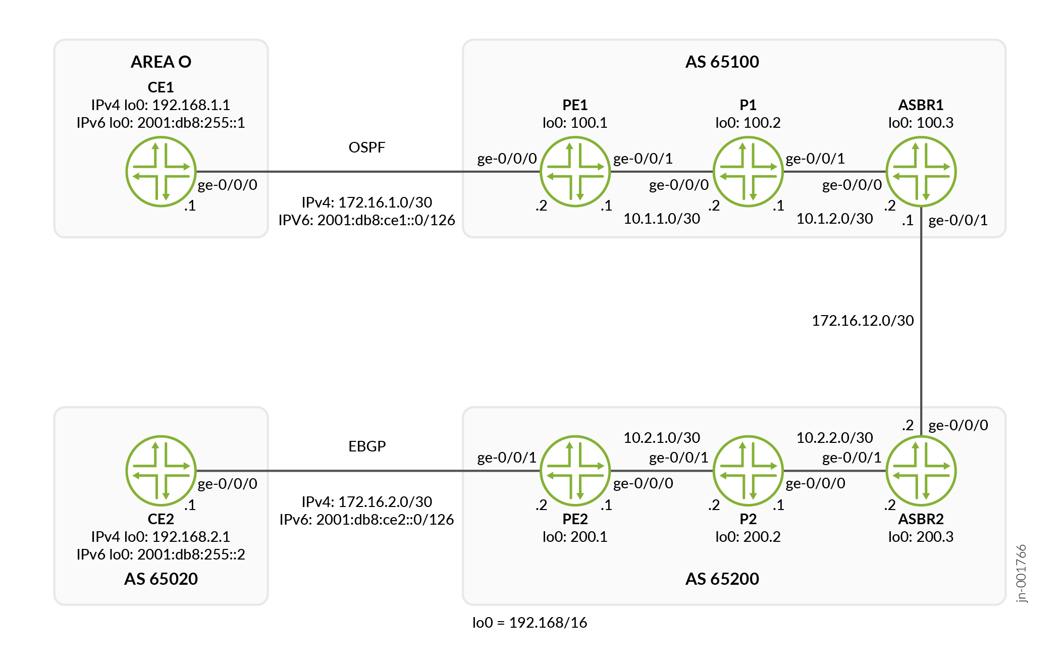
Interprovider Layer 3 VPN Option B can be configured to carry IPv6 customer traffic while maintaining an IPv4 MPLS core. This example builds on the Interprovider Layer 3 VPN Option B example presented above and describes the configuration changes required to support IPv6 VPN services.
Figure 4 shows the Interprovider Layer 3 VPN Option B topology from the example above with both IPv4 and IPv6 addresses. Table 1 displays the IPv4 and corresponding IPv6 addresses that will be use in this example .
| Description | IPv4 | IPv6 |
|---|---|---|
|
CE1 Loopback Address |
192.168.1.1/32 |
2001:db8:255::1/128 |
|
CE1 Gigabit Ethernet Interface (ge-0/0/0) |
172.16.1.1/30 |
2001:db8:ce1::1/126 |
|
PE1 Gigabit Ethernet Interface (ge-0/0/0) |
172.16.1.2/30 |
2001:db8:ce1::2/126 |
|
PE2 Gigabit Ethernet Interface (ge-0/0/1) |
172.16.2.2/30 |
2001:db8:ce2::2/126 |
|
CE2 Gigabit Ethernet Interface (ge-0/0/0) |
172.16.2.1/30 |
2001:db8:ce2::1/126 |
|
CE2 Loopback address |
192.168.2.1/32 |
2001:db8:255::2/128 |
|
ASBR1 Gigabit Ethernet Interface (ge-0/0/1) |
172.16.12.1/30 |
::172.16.12.1/126 |
|
ASBR2 Gigabit Ethernet Interface (ge-0/0/0) |
172.16.12.2/30 |
::172.16.12.2/126 |
Configuration
Starting with the existing configuration above, complete the following steps:
- Configuring Router CE1
- Configuring Router PE1
- Configuring Router ASBR1
- Configuring Router ASBR2
- Configuring Router PE2
- Configuring Router CE2
- Verifying the VPN Operation
Configuring Router CE1
Step-by-Step Procedure
On Router CE1, configure the IPv6 address and protocol family on the logical loopback interface and on the dual-stack Ethernet interface connected to Router PE1.
Note: Dual-stack interfaces allow us to assign both IPv4 and IPv6 addresses on the same logical interface.user@CE1# set interfaces ge-0/0/0 unit 0 family inet6 address 2001:db8:ce1::1/126 set interfaces lo0 unit 0 family inet6 address 2001:db8:255::1/128
On Router CE1, configure OSPFv3 on the router. Since OSPFv3 supports both IPv4 and IPv6 address families, we will replace the older OSPF configuration use OSPFv3 in it's place.
user@CE1#
delete protocols ospf
set protocols ospf3 realm ipv4-unicast area 0.0.0.0 interface ge-0/0/0.0
set protocols ospf3 realm ipv4-unicast area 0.0.0.0 interface lo0.0
set protocols ospf3 area 0.0.0.0 interface ge-0/0/0.0
set protocols ospf3 area 0.0.0.0 interface lo0.0
Configuring Router PE1
Step-by-Step Procedure
On Router PE1, configure an IPv6 address and the
inet6address family on the interface connected to CE1.user@PE1# set interfaces ge-0/0/0 unit 0 family inet6 address 2001:db8:ce1::2/126
- On Router PE1, configure the to_CE2 routing instance to support IPv6 protocols.
Replace the existing configuration with the older OSPF protocol with OSPFv3. By
default, BGP does not advertise directly connected routes in a Layer 3 VPN network.
Configuring the vrf-table-label removes the default constraint and allows the
connected routes to be advertised.
user@PE1#
delete routing-instances to_CE1 protocols ospf
set routing-instances to_CE1 protocols ospf3 realm ipv4-unicast area 0.0.0.0 interface ge-0/0/0.0
set routing-instances to_CE1 protocols ospf3 realm ipv4-unicast export bgp-to-ospf
set routing-instances to_CE1 protocols ospf3 area 0.0.0.0 interface ge-0/0/0.0
set routing-instances to_CE1 protocols ospf3 export bgp-to-ospf
set routing-instances to_CE1 vrf-table-label
On Router PE1, configure the
to-ASBR1BGP group and MPLS protocol to support IPv6 VPNs by enabling theinet6-vpnaddress family. EnableIPv6-tunnelingto allow IPv6 VPN traffic to traverse the existing IPv4 MPLS core. This configuration populates the routing table with IPv4-mapped IPv6 next-hop entries derived from MPLS transport routes oninet6.0routing table.user@PE1# set protocols bgp group to-ASBR1 neighbor 192.168.100.3 family inet6-vpn unicast set protocols mpls ipv6-tunneling
On Router PE1, configure the policy to include support for direct and ospfv3 routes.
user@PE1#
delete policy-options policy-statement vpnexport term 1 from protocol ospf.
set policy-options policy-statement vpnexport term 1 from protocol direct
set policy-options policy-statement vpnexport term 1 from protocol ospf3
Configuring Router ASBR1
Step-by-Step Procedure
On Router ASBR1, configure IPv6 address and the
inet6address family on the interface connected ASBR2.user@ASBR1# set interfaces ge-0/0/1 unit 0 family inet6 address ::172.16.12.1/126
On Router ASBR1, update the
to-PE1and theto-ASBR2BGP groups to supportinet6-vpn. EnableIPv6-tunnelingto support IPv6 VPN traffic across the IPv4 MPLS core.user@ASBR1# set protocols bgp group to-PE1 neighbor 192.168.100.1 family inet6-vpn unicast set protocols bgp group to-ASBR2 neighbor ::172.16.12.2 family inet6-vpn unicast set protocols bgp group to-ASBR2 neighbor ::172.16.12.2 peer-as 65200 set protocols mpls ipv6-tunneling
Configuring Router ASBR2
Step-by-Step Procedure
On Router ASBR2, configure IPv6 address and the
inet6address family on the interface connected ASBR1.user@ASBR2# set interfaces ge-0/0/0 unit 0 family inet6 address ::172.16.12.2/126
On Router ASBR2, update the
to-PE2and theto-ASBR1BGP groups to supportinet6-vpn. EnableIPv6-tunnelingto support IPv6 VPN traffic across the IPv4 MPLS core.user@ASBR2# set protocols bgp group to-PE2 neighbor 192.168.200.1 family inet6-vpn unicast set protocols bgp group to-ASBR1 neighbor ::172.16.12.1 family inet6-vpn unicast set protocols bgp group to-ASBR1 neighbor ::172.16.12.1 peer-as 65100 set protocols mpls ipv6-tunneling
Configuring Router PE2
Step-by-Step Procedure
On Router PE2, configure an IPv6 address and the
inet6address family on the interface connected to CE2.user@PE2# set interfaces ge-0/0/1 unit 0 family inet6 address 2001:db8:ce2::2/126
On Router PE2, configure the
to_CE2routing-instance to support IPv6.user@PE2# set routing-instances to_CE2 protocols bgp group to_CE2 neighbor 2001:db8:ce2::1 family inet6 unicast set routing-instances to_CE2 protocols bgp group to_CE2 neighbor 2001:db8:ce2::1 peer-as 65020
On Router PE2, configure the
to-ASBR2BGP group and MPLS protocol to support IPv6 VPNs. Enable IPv6 tunnel for MPLS to support IPv6 addresses across an IPv4 core.user@PE2# set protocols bgp group to-ASBR2 neighbor 192.168.200.3 family inet6-vpn unicast set protocols mpls ipv6-tunneling
On Router PE2, configure the policy to include support for direct and ospfv3 routes.
user@PE2#
set policy-options policy-statement vpnexport term 1 from protocol direct
Configuring Router CE2
Step-by-Step Procedure
On Router CE2, configure the IPv6 address and protocol family on the logical loopback interface and on the interface connected to Router PE1.
user@CE2#
set interfaces ge-0/0/0 unit 0 family inet6 address 2001:db8:ce2::1/126
set interfaces lo0 unit 0 family inet6 address 2001:db8:255::2/128
Configure the loopback policy to match for the IPv6 loopback address.
user@CE2#
set policy-options policy-statement loopback term 2 from family inet6
set policy-options policy-statement loopback term 2 from route-filter 2001:db8:255::2/128 exact
set policy-options policy-statement loopback term 2 then accept
On Router CE2, configure the
to_PE2BGP group so support IPv6 route exchange by enabling theinet6address family.user@CE2# set protocols bgp group to_PE2 neighbor 2001:db8:ce2::2 family inet6 unicast
Verifying the VPN Operation
Step-by-Step Procedure
-
Commit the configuration on each router.
On Router PE1, display the routes for the to_CE1 routing instance with the
show ospf3 routecommand. Verify that the device has learned2001:db8:255::1/128route.user@PE1> show ospf3 route instance to_CE1 set protocols bgp group to_PE2 neighbor 2001:db8:ce2::2 family inet6 unicast Prefix Path Route NH Metric Type Type Type 192.168.1.1 Intra Router IP 1 NH-interface ge-0/0/0.0, NH-addr fe80::5604:27ff:fe00:606d 192.168.1.1;0.0.0.2 Intra Transit IP 1 NH-interface ge-0/0/0.0 2001:db8:255::1/128 Intra Network IP 1 NH-interface ge-0/0/0.0, NH-addr fe80::5604:27ff:fe00:606d 2001:db8:ce1::/126 Intra Network IP 1 NH-interface ge-0/0/0.0On Router PE1, use the show
route advertising-protocolcommand to verify that Router PE1 advertises the2001:db8:255::1route to Router ASBR1 using MP-BGP with the VPN MPLS label.user@PE1> show route advertising-protocol bgp 192.168.100.3 table to_CE1.inet6.0 extensive to_CE1.inet6.0: 9 destinations, 9 routes (9 active, 0 holddown, 0 hidden) * 2001:db8:255::1/128 (1 entry, 1 announced) BGP group to-ASBR1 type Internal Route Distinguisher: 192.168.100.1:1 VPN Label: 16 Nexthop: Self Flags: Nexthop Change MED: 1 Localpref: 100 AS path: [65100] I Communities: target:65100:1 rte-type:0.0.0.0:1:0 * 2001:db8:ce1::/126 (1 entry, 1 announced) BGP group to-ASBR1 type Internal Route Distinguisher: 192.168.100.1:1 VPN Label: 16 Nexthop: Self Flags: Nexthop Change Localpref: 100 AS path: [65100] I Communities: target:65100:1On Router ASBR1, use the
show route receive-protocolcommand to verify that the router receives and accepts the2001:db8:255::1/128route and places it in thebgp.l3vpn-inet6.0routing table.user@ASBR1> show route receive-protocol bgp 192.168.100.1 table bgp.l3vpn-inet6.0 extensive bgp.l3vpn-inet6.0: 5 destinations, 5 routes (5 active, 0 holddown, 0 hidden) * 192.168.100.1:1:2001:db8:255::1/128 (1 entry, 1 announced) Accepted Route Distinguisher: 192.168.100.1:1 VPN Label: 16 Nexthop: ::ffff:192.168.100.1 MED: 1 Localpref: 100 AS path: I Communities: target:65100:1 rte-type:0.0.0.0:1:0 * 192.168.100.1:1:2001:db8:ce1::/126 (1 entry, 1 announced) Accepted Route Distinguisher: 192.168.100.1:1 VPN Label: 16 Nexthop: ::ffff:192.168.100.1 Localpref: 100 AS path: I Communities: target:65100:1On Router ASBR1, use the
show route table bgp.l3vpn-inet6.0command to verify that the IPv6 VPN routes from CE1 has been stored.user@ASBR1> show route table bgp.l3vpn-inet6.0 bgp.l3vpn-inet6.0: 5 destinations, 5 routes (5 active, 0 holddown, 0 hidden) + = Active Route, - = Last Active, * = Both 192.168.100.1:1:2001:db8:255::1/128 *[BGP/170] 1d 04:57:45, MED 1, localpref 100, from 192.168.100.1 AS path: I, validation-state: unverified > to 10.1.2.1 via ge-0/0/0.0, label-switched-path to-PE1 192.168.100.1:1:2001:db8:ce1::/126 *[BGP/170] 1d 04:57:45, localpref 100, from 192.168.100.1 AS path: I, validation-state: unverified > to 10.1.2.1 via ge-0/0/0.0, label-switched-path to-PE1 192.168.200.1:1:2001:db8:255::2/128 *[BGP/170] 1d 04:29:43, localpref 100 AS path: 65200 65020 I, validation-state: unverified > to ::172.16.12.2 via ge-0/0/1.0, Push 299984 192.168.200.1:1:2001:db8:ce2::/126 *[BGP/170] 1d 04:29:43, localpref 100 AS path: 65200 I, validation-state: unverified > to ::172.16.12.2 via ge-0/0/1.0, Push 299984On Router ASBR2, use the
show route table bgp.l3vpn-inet6.0command to verify that the IPv6 VPN routes from CE1 has been stored.user@ASBR2> show route table bgp.l3vpn-inet6.0 bgp.l3vpn-inet6.0: 5 destinations, 5 routes (5 active, 0 holddown, 0 hidden) + = Active Route, - = Last Active, * = Both 192.168.100.1:1:2001:db8:255::1/128 *[BGP/170] 1d 04:41:18, localpref 100 AS path: 65100 I, validation-state: unverified > to ::172.16.12.1 via ge-0/0/0.0, Push 299952 192.168.100.1:1:2001:db8:ce1::/126 *[BGP/170] 1d 04:41:18, localpref 100 AS path: 65100 I, validation-state: unverified > to ::172.16.12.1 via ge-0/0/0.0, Push 299952 192.168.200.1:1:2001:db8:255::2/128 *[BGP/170] 1d 04:37:36, localpref 100, from 192.168.200.1 AS path: 65020 I, validation-state: unverified > to 10.2.2.1 via ge-0/0/1.0, label-switched-path to-PE2 192.168.200.1:1:2001:db8:ce2::/126 *[BGP/170] 1d 04:37:37, localpref 100, from 192.168.200.1 AS path: I, validation-state: unverified > to 10.2.2.1 via ge-0/0/1.0, label-switched-path to-PE2On Router ASBR2, use the
show route advertising-protocolcommand to verify that Router ASBR2 advertises the192.168.1.1route to Router PE2user@ASBR2> show route advertising-protocol bgp 192.168.200.1 table bgp.l3vpn-inet6.0 extensive bgp.l3vpn-inet6.0: 5 destinations, 5 routes (5 active, 0 holddown, 0 hidden) * 192.168.100.1:1:2001:db8:255::1/128 (1 entry, 1 announced) BGP group to-PE2 type Internal Route Distinguisher: 192.168.100.1:1 VPN Label: 299952 Nexthop: Self Flags: Nexthop Change Localpref: 100 AS path: [65200] 65100 I Communities: target:65100:1 rte-type:0.0.0.0:1:0 * 192.168.100.1:1:2001:db8:ce1::/126 (1 entry, 1 announced) BGP group to-PE2 type Internal Route Distinguisher: 192.168.100.1:1 VPN Label: 299952 Nexthop: Self Flags: Nexthop Change Localpref: 100 AS path: [65200] 65100 I Communities: target:65100:1On Router PE2, use the
show route receive-protocolcommand to verify that the router receives and accepts the192.168.1.1route and places it in theto_CE2.inet6.0routing tableuser@PE2> show route receive-protocol bgp 192.168.200.3 table to_CE2.inet6.0 extensive to_CE2.inet6.0: 8 destinations, 8 routes (8 active, 0 holddown, 0 hidden) * 2001:db8:255::1/128 (1 entry, 1 announced) Import Accepted Route Distinguisher: 192.168.100.1:1 VPN Label: 299952 Nexthop: ::ffff:192.168.200.3 Localpref: 100 AS path: 65100 I Communities: target:65100:1 rte-type:0.0.0.0:1:0 * 2001:db8:ce1::/126 (1 entry, 1 announced) Import Accepted Route Distinguisher: 192.168.100.1:1 VPN Label: 299952 Nexthop: ::ffff:192.168.200.3 Localpref: 100 AS path: 65100 I Communities: target:65100:1On Router PE2, use the
show routecommand to verify that Router CE2 received the 2001:db8:255::1 route from Router PE2.user@PE2> show route 2001:db8:255::1 to_CE2.inet6.0: 8 destinations, 8 routes (8 active, 0 holddown, 0 hidden) + = Active Route, - = Last Active, * = Both 2001:db8:255::1/128*[BGP/170] 1d 05:01:41, localpref 100, from 192.168.200.3 AS path: 65100 I, validation-state: unverified > to 10.2.1.2 via ge-0/0/0.0, label-switched-path to-ASBR2On Router CE2, use the
show routecommand to verify that Router CE2 receives the 2001:db8:255::1 route from Router PE2.user@CE2> show route 2001:db8:255::1 inet6.0: 10 destinations, 10 routes (10 active, 0 holddown, 0 hidden) + = Active Route, - = Last Active, * = Both 2001:db8:255::1/128*[BGP/170] 1d 05:04:45, localpref 100 AS path: 65200 65100 I, validation-state: unverified > to 2001:db8:ce2::2 via ge-0/0/0.0 user@CE2> show route 2001:db8:ce1::1 inet6.0: 10 destinations, 10 routes (10 active, 0 holddown, 0 hidden) + = Active Route, - = Last Active, * = Both 2001:db8:ce1::/126 *[BGP/170] 1d 05:04:53, localpref 100 AS path: 65200 65100 I, validation-state: unverified > to 2001:db8:ce2::2 via ge-0/0/0.0On Router CE2, use the
pingcommand and specify2001:db8:255::2as the source of the ping packets to verify connectivity with Router CE1.user@CE2> ping 2001:db8:255::1 source 2001:db8:255::2 count 2 PING6(56=40+8+8 bytes) 2001:db8:255::2 --> 2001:db8:255::1 16 bytes from 2001:db8:255::1, icmp_seq=0 hlim=58 time=9.833 ms 16 bytes from 2001:db8:255::1, icmp_seq=1 hlim=58 time=8.846 ms --- 2001:db8:255::1 ping6 statistics --- 2 packets transmitted, 2 packets received, 0% packet loss round-trip min/avg/max/std-dev = 8.846/9.340/9.833/0.493 ms
Example: Configuring Interprovider Layer 3 VPN Option C
Interprovider Layer 3 VPN Option C provides interprovider multihop EBGP redistribution of labeled VPN-IPv4 routes between source and destination ASs, with EBGP redistribution of labeled IPv4 routes from AS to neighboring AS. Compared to Option A and Option B, Option C is the most scalable solution. To configure an interprovider Layer 3 VPN option C service, you need to configure the AS border routers and the PE routers connected to the end customer’s CE routers using multihop EBGP.
This example provides a step-by-step procedure to configure interprovider layer 3 VPN option C, which is one of the recommended implementations of MPLS VPN when that service is required by a customer that has more than one AS but not all of the customer’s ASs can be serviced by the same service provider (SP). It is organized in the following sections:
Requirements
This example requires the following hardware and software components:
-
Junos OS Release 9.5 or later.
-
Eight Juniper Networks M Series Multiservice Edge Routers, T Series Core Routers, TX Matrix Routers, or MX Series 5G Universal Routing Platforms.
Configuration Overview and Topology
Interprovider layer 3 VPN option C is a very scalable interprovider VPN solution to the problem of providing VPN services to a customer that has different sites, not all of which can use the same SP.
RFC 4364 section 10, refers to this method as multihop EBGP redistribution of labeled VPN-IPv4 routes between source and destination ASs, with EBGP redistribution of labeled IPv4 routes from AS to neighboring AS.
This solution is similar to the solution described in Implementing Interprovider Layer 3 VPN Option B, except internal IPv4 unicast routes are advertised instead of external VPN-IPv4-unicast routes, using EBGP. Internal routes are internal to leaf SPs (SP1 and SP2 in this example), and external routes are those learned from the end customer requesting VPN services.
In this configuration:
-
After the loopback address of Router PE2 is learned by Router PE1 and the loopback address of Router PE1 is learned by Router PE2, the end PE routers establish an MP-EBGP session for exchanging VPN-IPv4 routes.
-
Since VPN-IPv4 routes are exchanged among end PE routers, any other router on the path from Router PE1 and Router PE2 does not need to keep or install VPN-IPv4 routes in their routing information base (RIB) or forwarding information base (FIB) tables.
-
An MPLS path needs to be established between Router PE1 and Router PE2.
RFC 4364 describes only one solution that uses a BGP labeled-unicast approach. In this approach, the ASBR routers advertise the loopback addresses of the PE routers and associate each prefix with a label according to RFC 3107. Service providers may use RSVP or LDP to establish an LSP between ASBR routers and PE routers in their internal network.
In this network, ASBR1 receives label information associated with the loopback IP address of Router PE1 and advertises another label to Router ASBR2 using MP-EBGP labeled-unicast. Meanwhile, the ASBRs build their own MPLS forwarding table according to the received and advertised routes and labels. Router ASBR1 uses its own IP address as the next-hop information.
Router ASBR2 receives this prefix associated with a label, assigns another label, changes the next-hop address to its own address, and advertises it to Router PE1. Router PE1 now has an update with the label information and next-hop to Router ASBR1. Also, Router PE1 already has a label associated with the IP address of Router ASBR1. If Router PE1 sends an IP packet to Router PE2, it pushes two labels: one for the IP address of Router PE2 (obtained using MP-IBGP labeled-unicast advertisement) and one for the IP address of Router ASBR1 (obtained using LDP or RSVP).
Router ASBR1 then pops the outer label and swaps the inner label with the label learned from a neighbor ASBR for its neighboring PE router. Router ASBR2 performs a similar function and swaps the incoming label (only one) and pushes another label that is associated with the address of Router PE2. Router PE2 pops both labels and passes the remaining IP packet to its own CPU. After the end-to-end connection among the PE routers is created, the PE routers establish an MP-EBGP session to exchange VPN-IPv4 routes.
In this solution, PE routers push three labels onto the IP packet coming from the VPN end user. The inner-most label, obtained using MP-EBGP, determines the correct VPN routing and forwarding (VRF) routing instance at the remote PE. The middle label is associated with the IP address of the remote PE and is obtained from an ASBR using MP-IBGP labeled-unicast. The outer label is associated with the IP addresses of the ASBRs and is obtained using LDP or RSVP.
The physical topology of the network is shown in Figure 5.
Topology
Configuration
The procedure presented here is written with the assumption that the reader is already familiar with MPLS MVPN configuration. This example focuses on explaining the unique configuration required for carrier-of-carriers solutions for VPN services to different sites.
To configure interprovider layer 3 VPN option C, perform the following tasks:
- Configuring Router CE1
- Configuring Router PE1
- Configuring Router P1
- Configuring Router ASBR1
- Configuring Router ASBR2
- Configuring Router P2
- Configuring Router PE2
- Configuring Router CE2
- Verifying the VPN Operation
Configuring Router CE1
Step-by-Step Procedure
-
On Router CE1, configure the IP address and protocol family on the Fast Ethernet interface for the link between Router CE1 and Router PE1. Specify the
inetaddress family type.[edit interfaces fe-0/0/1.0] family inet { address 198.51.100.1/24; } -
On Router CE1, configure the IP address and protocol family on the loopback interface. Specify the
inetaddress family type.[edit interfaces lo0] unit 0 { family inet { address 192.0.2.1/32; } } -
On Router CE1, configure a routing protocol. The routing protocol can be a static route, RIP, OSPF, IS-IS, or EBGP. In this example we configure OSPF. Include the logical interface for the link between Router CE1 and Router PE1 and the logical loopback interface of Router CE1.
[edit protocols]
ospf {
    area 0.0.0.2 {
        interface fe-0/0/1.0;
        interface lo0.0 {
            passive;
        }
    }
}
Configuring Router PE1
Step-by-Step Procedure
-
On Router PE1, configure IPv4 addresses on the SONET, Fast Ethernet, and logical loopback interfaces. Specify the
inetaddress family on all of the interfaces. Specify themplsaddress family on the SONET interfaces.[edit interfaces] so-0/2/0 { unit 0 { family inet { address 192.168.1.2/24; } family mpls; } } fe-1/2/3 { unit 0 { family inet { address 198.51.100.3/24; } } } lo0 { unit 0 { family inet { address 192.0.2.2/32; } } } -
On Router PE1, configure the routing instance for VPN2. Specify the
vrfinstance type and specify the customer-facing Fast Ethernet interface. Configure a route distinguisher to create a unique VPN-IPv4 address prefix. Apply the VRF import and export policies to enable the sending and receiving of route targets. Configure the OSPF protocol within the VRF. Specify the customer-facing Fast Ethernet interface and specify the export policy to export BGP routes into OSPF.[edit routing-instances] vpn2CE1 { instance-type vrf; interface fe-1/2/3.0; route-distinguisher 1:100; vrf-import vpnimport; vrf-export vpnexport; protocols { ospf { export bgp-to-ospf; area 0.0.0.2 { interface fe-1/2/3.0; } } } } -
On Router PE1, configure the RSVP and MPLS protocols to support the LSP. Configure the LSP to Router ASBR1 and specify the IP address of the logical loopback interface on Router ASBR1. Configure the OSPF protocol. Specify the core-facing SONET interface and specify the logical loopback interface on Router PE1.
[edit protocols] rsvp { interface so-0/2/0.0; interface lo0.0; } mpls { label-switched-path To-ASBR1 { to 192.0.2.4; } interface so-0/2/0.0; interface lo0.0; } ospf { traffic-engineering; area 0.0.0.0 { interface so-0/2/0.0; interface lo0.0 { passive; } } } -
On Router PE1, configure the
To_ASBR1peer BGP group. Specify the group type asinternal. Specify the local address as the logical loopback interface on Router PE1. Specify the neighbor address as the logical loopback interface on Router ASBR1. Specify theinetaddress family. For a PE router to install a route in the VRF, the next hop must resolve to a route stored within theinet.3table. Thelabeled-unicast resolve-vpnstatements allow labeled routes to be placed in theinet.3routing table for route resolution, which are then resolved for PE router connections where the remote PE is located across another AS.[edit protocols] bgp { group To_ASBR1 { type internal; local-address 192.0.2.2; neighbor 192.0.2.4 { family inet { labeled-unicast { resolve-vpn; } } } } } -
On Router PE1, configure multihop EBGP toward PE2. Specify the
inet-vpnfamily.[edit protocols] bgp { group To_PE2 { multihop { ttl 20; } local-address 192.0.2.2; family inet-VPN { unicast; } neighbor 192.0.2.7 { peer-as 200; } } } -
On Router PE1, configure the BGP local autonomous system number.
[edit routing-options]
autonomous-system 100;
-
On Router PE1, configure a policy to export the BGP routes into OSPF.
[edit policy-options] policy-statement bgp-to-ospf { term 1 { from protocol bgp; then accept; } term 2 { then reject; } } -
On Router PE1, configure a policy to add the VRF route target to the routes being advertised for this VPN.
[edit policy-options] policy-statement vpnexport { term 1 { from protocol ospf; then { community add test_comm; accept; } } term 2 { then reject; } } -
On Router PE1, configure a policy to import routes from BGP that have the
test_commcommunity attached.[edit policy-options] policy-statement vpnimport { term 1 { from { protocol bgp; community test_comm; } then accept; } term 2 { then reject; } } -
On Router PE1, define the
test_commBGP community with a route target.[edit policy-options] community test_comm members target:1:100;
Configuring Router P1
Step-by-Step Procedure
-
On Router P1, configure IP addresses for the SONET and Gigabit Ethernet interfaces. Enable the interfaces to process the
inetandmplsaddress families. Configure the IP address for thelo0.0loopback interface and enable the interface to process theinetaddress family.[edit interfaces] so-0/2/1 { unit 0 { family inet { address 192.168.1.4/24; } family mpls; } } ge-1/3/0 { unit 0 { family inet { address 192.168.2.5/24; } family mpls; } } lo0 { unit 0 { family inet { address 192.0.2.3/32; } } } -
On Router P1, configure the RSVP and MPLS protocols to support the LSP. Specify the SONET and Gigabit Ethernet interfaces.
Configure the OSPF protocol. Specify the SONET and Gigabit Ethernet interfaces and specify the logical loopback interface. Enable OSPF to support traffic engineering extensions.
[edit protocols]
rsvp {
    interface so-0/2/1.0;
    interface ge-1/3/0.0;
    interface lo0.0;
}
mpls {
    interface lo0.0;
    interface ge-1/3/0.0;
    interface so-0/2/1.0;
}
ospf {
    traffic-engineering;
    area 0.0.0.0 {
        interface ge-1/3/0.0;
        interface so-0/2/1.0;
        interface lo0.0 {
            passive;
        }
    }
}
Configuring Router ASBR1
Step-by-Step Procedure
-
On Router ASBR1, configure IP addresses for the Gigabit Ethernet interfaces. Enable the interfaces to process the
inetandmplsaddresses families. Configure the IP addresses for thelo0.0loopback interface and enable the interface to process theinetaddress family.[edit interfaces] ge-0/0/0 { unit 0 { family inet { address 192.168.2.6/24; } family mpls; } } ge-0/1/1 { unit 0 { family inet { address 192.168.3.7/24; } family mpls; } } lo0 { unit 0 { family inet { address 192.0.2.4/32; } } } -
On Router ASBR1, configure the protocols to support the LSP.
Configure the RSVP protocol by specifying the Gigabit Ethernet interface that is facing the P1 router and the logical loopback interface.
Configure the MPLS protocol by specifying the Gigabit Ethernet interfaces and the logical loopback interface. Include the
traffic-engineering
bgp-igp-both-ribs
statement at the[edit protocols mpls]hierarchy level.Configure the OSPF protocol on the Gigabit Ethernet interface facing the P1 router and the logical loopback interface. Enable OSPF to support traffic engineering extensions.
[edit protocols] rsvp { interface ge-0/0/0.0; interface lo0.0; } mpls { traffic-engineering bgp-igp-both-ribs; label-switched-path To_PE1 { to 192.0.2.2; } interface lo0.0; interface ge-0/0/0.0; interface ge-0/1/1.0; } ospf { traffic-engineering; area 0.0.0.0 { interface ge-0/0/0.0; interface lo0.0 { passive; } } } -
On Router ASBR1, create the
To-PE1internal BGP peer group. Specify the local IP peer address as the locallo0.0address. Specify the neighbor IP peer address as the Gigabit Ethernet interface address of Router PE1.[edit protocols] bgp { group To-PE1 { type internal; local-address 192.0.2.4; neighbor 192.0.2.2 { family inet { labeled-unicast; } export next-hop-self; } } -
On Router ASBR1, create the
To-ASBR2external BGP peer group. Enable the router to use BGP to advertise network layer reachability information (NLRI) for unicast routes. Specify the neighbor IP peer address as the Gigabit Ethernet interface address on Router ASBR2.[edit protocols] group To-ASBR2 { type external; family inet { labeled-unicast; } export To-ASBR2; neighbor 192.168.3.8 { peer-as 200; } } -
On Router ASBR1, configure the BGP local autonomous system number.
[edit routing-options]
autonomous-system 100;
-
On Router ASBR 1, configure a policy to import routes from BGP that match the 192.0.2.2/24 route.
[edit policy-options] policy-statement To-ASBR2 { term 1 { from { route-filter 192.0.2.2/32 exact; } then accept; } term 2 { then reject; } -
On Router ASBR 1, define a next-hop self policy and apply it to the IBGP sessions.
[edit policy-options]
policy-statement next-hop-self {
    then {
        next-hop self;
    }
}
Configuring Router ASBR2
Step-by-Step Procedure
-
On Router ASBR2, configure IP addresses for the Gigabit Ethernet interfaces. Enable the interfaces to process the
inetandmplsaddress families. Configure the IP address for thelo0.0loopback interface and enable the interface to process theinetaddress family.[edit interfaces] ge-0/1/1 { unit 0 { family inet { address 192.168.3.8/24; } family mpls; } } ge-0/2/3 { unit 0 { family inet { address 192.168.4.9/24; } family mpls; } } lo0 { unit 0 { family inet { address 192.0.2.5/32; } } } -
On Router ASBR2, configure the protocols to support the LSP.
Configure the RSVP protocol by specifying the Gigabit Ethernet interface facing the P2 router and the logical loopback interface .
Configure the MPLS protocol by specifying the Gigabit Ethernet interfaces and the logical loopback interface. Include the
traffic-engineering
bgp-igp-both-ribs
statement at the[edit protocols mpls]hierarchy level.Configure the OSPF protocol on the Gigabit Ethernet interface facing the P2 router and the logical loopback interface . Enable OSPF to support traffic engineering extensions.
[edit protocols] rsvp { interface ge-0/2/3.0; interface lo0.0; } mpls { traffic-engineering bgp-igp-both-ribs; label-switched-path To_PE2 { to 192.0.2.7; } interface lo0.0 interface ge-0/2/3.0; interface ge-0/1/1.0; } ospf { traffic-engineering; area 0.0.0.0 { interface ge-0/2/3.0; interface lo0.0 { passive; } } } -
On Router ASBR2, create the
To-PE2internal BGP peer group. Specify the local IP peer address as the locallo0.0address. Specify the neighbor IP peer address as thelo0.0interface address of Router PE2.[edit protocols] bgp { group To-PE2 { type internal; local-address 192.0.2.5; export next-hop-self; neighbor 192.0.2.7 { family inet { labeled-unicast; } export next-hop-self; } } } -
On Router ASBR2, create the
To-ASBR1external BGP peer group. Enable the router to use BGP to advertise NLRI for unicast routes. Specify the neighbor IP peer address as the Gigabit Ethernet interface address on Router ASBR1.[edit protocols] bgp { group To-ASBR1 { type external; family inet { labeled-unicast; } export To-ASBR1; neighbor 192.168.3.7 { peer-as 100; } } } -
On Router ASBR2 configure the BGP local autonomous system number.
[edit routing-options]
autonomous-system 200;
-
On Router ASBR2, configure a policy to import routes from BGP that match the
192.0.2.7/24route.[edit policy-options] policy-statement To-ASBR1 { term 1 { from { route-filter 192.0.2.7/32 exact; } then accept; } term 2 { then reject; } } -
On Router ASBR 2, define a next-hop self policy.
[edit policy-options]
policy-statement next-hop-self {
    then {
        next-hop self;
    }
}
Configuring Router P2
Step-by-Step Procedure
-
On Router P2, configure IP addresses for the SONET and Gigabit Ethernet interfaces. Enable the interfaces to process the
inetandmplsaddresses families. Configure the IP addresses for thelo0.0loopback interface and enable the interface to process theinetaddress family.[edit interfaces] so-0/0/0 { unit 0 { family inet { address 192.168.5.10/24; } family mpls; } } ge-0/2/2 { unit 0 { family inet { address 192.168.4.11/24; } family mpls; } } lo0 { unit 0 { family inet { address 192.0.2.6/32; } } } -
On Router P2, configure the RSVP and MPLS protocols to support the LSP. Specify the SONET and Gigabit Ethernet interfaces.
Configure the OSPF protocol. Specify the SONET and Gigabit Ethernet interfaces and specify the logical loopback interface. Enable OSPF to support traffic engineering extensions.
[edit protocols]
rsvp {
    interface so-0/0/0.0;
    interface ge-0/2/2.0;
    interface lo0.0;
}
mpls {
    interface lo0.0;
    interface ge-0/2/2.0;
    interface so-0/0/0.0;
}
ospf {
    traffic-engineering;
    area 0.0.0.0 {
        interface ge-0/2/2.0;
        interface so-0/0/0.0;
        interface lo0.0 {
            passive;
        }
    }
}
Configuring Router PE2
Step-by-Step Procedure
-
On Router PE2, configure IPv4 addresses on the SONET, Fast Ethernet, and logical loopback interfaces. Specify the
inetaddress family on all of the interfaces. Specify themplsaddress family on the SONET interface.[edit interfaces] so-0/0/1 { unit 0 { family inet { address 192.168.5.12/24; } family mpls; } } fe-0/3/1 { unit 0 { family inet { address 192.168.6.13/24; } } } lo0 { unit 0 { family inet { address 192.0.2.7/32; } } } -
On Router PE2, configure the routing instance for VPN2. Specify the
vrfinstance type and specify the customer-facing Fast Ethernet interface. Configure a route distinguisher to create a unique VPN-IPv4 address prefix. Apply the VRF import and export policies to enable the sending and receiving of route targets. Configure the BGP peer group within the VRF. Specify AS20as the peer AS and specify the IP address of the Fast Ethernet interface on Router CE1 as the neighbor address.[edit routing-instances] vpn2CE2 { instance-type vrf; interface fe-0/3/1.0; route-distinguisher 1:100; vrf-import vpnimport; vrf-export vpnexport; protocols { bgp { group To_CE2 { peer-as 20; neighbor 192.168.6.14; } } } } -
On Router PE2, configure the RSVP and MPLS protocols to support the LSP. Configure the LSP to ASBR2 and specify the IP address of the logical loopback interface on Router ASBR2. Configure the OSPF protocol. Specify the core-facing SONET interface and specify the logical loopback interface on Router PE2.
[edit protocols] rsvp { interface so-0/0/1.0; interface lo0.0; } mpls { label-switched-path To-ASBR2 { to 192.0.2.5; } interface so-0/0/1.0; interface lo0.0; } ospf { traffic-engineering; area 0.0.0.0 { interface so-0/0/1.0; interface lo0.0 { passive; } } } -
On Router PE2, configure the
To_ASBR2BGP group. Specify the group type asinternal. Specify the local address as the logical loopback interface on Router PE2. Specify the neighbor address as the logical loopback interface on the Router ASBR2.[edit protocols] bgp { group To_ASBR2 { type internal; local-address 192.0.2.7; neighbor 192.0.2.5 { family inet { labeled-unicast { resolve-vpn; } } } } } -
On Router PE2, configure multihop EBGP towards Router PE1 Specify the
inet-vpnaddress family.[edit protocols] bgp { group To_PE1 { type external; local-address 192.0.2.7; multihop { ttl 20; } family inet-vpn { unicast; } neighbor 192.0.2.2 { peer-as 100; } } } -
On Router PE2, configure the BGP local autonomous system number.
[edit routing-options]
autonomous-system 200;
-
On Router PE2, configure a policy to add the VRF route target to the routes being advertised for this VPN.
[edit policy-options] policy-statement vpnexport { term 1 { from protocol bgp; then { community add test_comm; accept; } } term 2 { then reject; } } -
On Router PE2, configure a policy to import routes from BGP that have the
test_commcommunity attached.[edit policy-options] policy-statement vpnimport { term 1 { from { protocol bgp; community test_comm; } then accept; } term 2 { then reject; } } -
On Router PE1, define the
test_commBGP community with a route target.[edit policy-options] community test_comm members target:1:100;
Configuring Router CE2
Step-by-Step Procedure
-
On Router CE2, configure the IP address and protocol family on the Fast Ethernet interface for the link between Router CE2 and Router PE2. Specify the
inetaddress family type.[edit interfaces] fe-3/0/0 { unit 0 { family inet { address 192.168.6.14/24; } } } -
On Router CE2, configure the IP address and protocol family on the loopback interface. Specify the
inetaddress family type.[edit interfaces lo0] lo0 { unit 0 { family inet { address 192.0.2.8/32; } } } -
On Router CE2, define a policy named
myroutesthat accepts direct routes.[edit policy-options] policy-statement myroutes { from protocol direct; then accept; } -
On Router CE2, configure a routing protocol. The routing protocol can be a static route, RIP, OSPF, IS-IS, or EBGP. In this example, we configure EBGP. Specify the BGP neighbor IP address as the logical loopback interface of Router PE1. Apply the
myroutespolicy.[edit protocols] bgp { group To_PE2 { neighbor 198.51.100.13 { export myroutes; peer-as 200; } } } -
On Router CE2, configure the BGP local autonomous system number.
[edit routing-options]
autonomous-system 20;
Verifying the VPN Operation
Step-by-Step Procedure
-
Commit the configuration on each router.
Note:The MPLS labels shown in this example will be different than the labels used in your configuration.
-
On Router PE1, display the routes for the
vpn2CE1routing instance using theshow ospf routecommand. Verify that the192.0.2.1route is learned from OSPF.user@PE1> show ospf route instance vpn2CE1 Topology default Route Table: Prefix Path Route NH Metric NextHop Nexthop Type Type Type Interface addr/label 192.0.2.1 Intra Router IP 1 fe-1/2/3.0 198.51.100.1 192.0.2.1/32 Intra Network IP 1 fe-1/2/3.0 198.51.100.1 198.51.100.0/24 Intra Network IP 1 fe-1/2/3.0 -
On Router PE1, use the
show route advertising-protocolcommand to verify that Router PE1 advertises the192.0.2.1route to Router PE2 using MP-BGP with the VPN MPLS label.user@PE1> show route advertising-protocol bgp 192.0.2.7 extensive bgp.l3vpn.0: 2 destinations, 2 routes (2 active, 0 holddown, 0 hidden) * 1:100:192.0.2.1/32 (1 entry, 1 announced) BGP group To_PE2 type External Route Distinguisher: 1:100 VPN Label: 300016 Nexthop: Self Flags: Nexthop Change MED: 1 AS path: [100] I Communities: target:1:100 rte-type:0.0.0.2:1:0 -
On Router ASBR1, use the
show route advertising-protocolcommand to verify that Router ASBR1 advertises the192.0.2.2route to Router ASBR2.user@ASBR1> show route advertising-protocol bgp 192.168.3,8 extensive inet.0: 14 destinations, 16 routes (14 active, 0 holddown, 0 hidden) * 192.0.2.2/32 (2 entries, 1 announced) BGP group To-PE2 type External Route Label: 300172 Nexthop: Self Flags: Nexthop Change MED: 2 AS path: [100] I -
On Router ASBR2, use the
show route receive-protocolcommand to verify that the router receives and accepts the192.0.2.2route .user@ASBR2> show route receive-protocol bgp 192.168.3.7 extensive inet.0: 10 destinations, 11 routes (10 active, 0 holddown, 0 hidden) * 192.0.2.2/32 (1 entry, 1 announced) Accepted Route Label: 300172 Nexthop: 192.168.3.7 MED: 2 AS path: 100 I -
On Router ASBR2, use the
show route advertising-protocolcommand to verify that Router ASBR2 advertises the192.0.2.2route to Router PE2.user@ASBR2> show route advertising-protocol bgp 192.0.2.7 extensive inet.0: 10 destinations, 11 routes (10 active, 0 holddown, 0 hidden) * 192.0.2.2/32 (1 entry, 1 announced) BGP group To-PE2 type Internal Route Label: 300192 Nexthop: Self Flags: Nexthop Change MED: 2 Localpref: 100 AS path: [200] 100 I -
On Router PE2, use the
show route receive-protocolcommand to verify that Router PE2 receives the route and puts it in theinet.0.routing table. Verify that Router PE2 also receives the update from Router PE1 and accepts the route.user@PE2> show route receive-protocol bgp 192.0.2.5 extensive inet.0: 13 destinations, 14 routes (13 active, 0 holddown, 0 hidden) * 192.0.2.2/32 (1 entry, 1 announced) Accepted Route Label: 300192 Nexthop: 192.0.2.5 MED: 2 Localpref: 100 AS path: 100 I AS path: Recorded inet.3: 2 destinations, 2 routes (2 active, 0 holddown, 0 hidden) * 192.0.2.2/32 (1 entry, 1 announced) Accepted Route Label: 300192 Nexthop: 192.0.2.5 MED: 2 Localpref: 100 AS path: 100 I AS path: Recorded -
On Router PE2, use the
show route receive-protocolcommand to verify that Router PE2 puts the route in the routing table of thevpn2CE2routing instance and advertises the route to Router CE2 using EBGP.user@PE2> show route receive-protocol bgp 192.0.2.2 detail inet.0: 17 destinations, 18 routes (17 active, 0 holddown, 0 hidden) inet.3: 6 destinations, 6 routes (6 active, 0 holddown, 0 hidden) __juniper_private1__.inet.0: 14 destinations, 14 routes (8 active, 0 holddown, 6 hidden) __juniper_private2__.inet.0: 1 destinations, 1 routes (0 active, 0 holddown, 1 hidden) vpn2CE2.inet.0: 4 destinations, 5 routes (4 active, 0 holddown, 0 hidden) * 192.0.2.1/32 (1 entry, 1 announced) Accepted Route Distinguisher: 1:100 VPN Label: 300016 Nexthop: 192.0.2.2 MED: 1 AS path: 100 I AS path: Recorded Communities: target:1:100 rte-type:0.0.0.2:1:0 iso.0: 1 destinations, 1 routes (1 active, 0 holddown, 0 hidden) mpls.0: 4 destinations, 4 routes (4 active, 0 holddown, 0 hidden) bgp.l3vpn.0: 2 destinations, 2 routes (2 active, 0 holddown, 0 hidden) * 1:100:192.0.2.1/32 (1 entry, 0 announced) Accepted Route Distinguisher: 1:100 VPN Label: 300016 Nexthop: 192.0.2.2 MED: 1 AS path: 100 I AS path: Recorded Communities: target:1:100 rte-type:0.0.0.2:1:0 __juniper_private1__.inet6.0: 4 destinations, 4 routes (4 active, 0 holddown, 0 hidden) -
On Router PE2, use the
show route advertising-protocolcommand to verify that Router PE2 advertises the192.0.2.1route to Router CE2 through thevpn2CE2peer group.user@PE2> show route advertising-protocol bgp 192.168.6.14 extensive vpn2CE2.inet.0: 4 destinations, 5 routes (4 active, 0 holddown, 0 hidden) * 192.0.2.1/32 (1 entry, 1 announced) BGP group vpn2CE2 type External Nexthop: Self AS path: [200] 100 I Communities: target:1:100 rte-type:0.0.0.2:1:0 -
On Router CE2, use the
show routecommand to verify that Router CE2 receives the192.0.2.1route from Router PE2.user@CE2> show route 192.0.2.1 inet.0: 6 destinations, 6 routes (6 active, 0 holddown, 0 hidden) + = Active Route, - = Last Active, * = Both 192.0.2.1/32 *[BGP/170] 00:25:36, localpref 100 AS path: 200 100 I > to 192.168.6.13 via fe-3/0/0.0 -
On Router CE2, use the
pingcommand and specify192.0.2.8as the source of the ping packets to verify connectivity with Router CE1.user@CE2> ping 192.0.2.1 source 192.0.2.8 PING 192.0.2.1 (192.0.2.1): 56 data bytes 64 bytes from 192.0.2.1: icmp_seq=0 ttl=58 time=4.786 ms 64 bytes from 192.0.2.1: icmp_seq=1 ttl=58 time=10.210 ms 64 bytes from 192.0.2.1: icmp_seq=2 ttl=58 time=10.588 ms
-
On Router PE2, use the
show routecommand to verify that the traffic is sent with an inner label of300016, a middle label of300192, and a top label of299776.user@PE2> show route 192.0.2.1 detail vpn2CE2.inet.0: 4 destinations, 5 routes (4 active, 0 holddown, 0 hidden) 192.0.2.1/32 (1 entry, 1 announced) *BGP Preference: 170/-101 Route Distinguisher: 1:100 Next hop type: Indirect Next-hop reference count: 3 Source: 192.0.2.2 Next hop type: Router, Next hop index: 653 Next hop: via so-0/0/1.0 weight 0x1, selected Label-switched-path To-ASBR2 Label operation: Push 300016, Push 300192, Push 299776(top) Protocol next hop: 192.0.2.2 Push 300016 Indirect next hop: 8c61138 262142 State: <Secondary Active Ext> Local AS: 200 Peer AS: 100 Age: 17:33 Metric: 1 Metric2: 2 Task: BGP_100.192.0.2.2+62319 Announcement bits (3): 0-RT 1-KRT 2-BGP RT Background AS path: 100 I AS path: Recorded Communities: target:1:100 rte-type:0.0.0.2:1:0 Accepted VPN Label: 300016 Localpref: 100 Router ID: 192.0.2.2 Primary Routing Table bgp.l3vpn.0 -
On Router ASBR2, use the
show route tablecommand to verify that Router ASBR2 receives the traffic after the top label is popped by Router P2. Verify that label300192is a swapped with label300176and the traffic is sent towards Router ASBR1 using interface ge-0/1/1.0. At this point, the bottom label300016is preserved.user@ASBR2# show route table mpls.0 detail 300192 (1 entry, 1 announced) *VPN Preference: 170 Next hop type: Router, Next hop index: 660 Next-hop reference count: 2 Source: 192.168.3.7 Next hop: 192.168.3.7 via ge-0/1/1.0, selected Label operation: Swap 300176 State: <Active Int Ext> Local AS: 200 Age: 24:01 Task: BGP RT Background Announcement bits (1): 0-KRT AS path: 100 I Ref Cnt: 1 -
On Router ASBR1, use the
show route tablecommand to verify that when Router ASBR1 receives traffic with label300176, it swaps the label with299824to reach Router PE1.user@ASBR1> show route table mpls.0 detail 300176 (1 entry, 1 announced) *VPN Preference: 170 Next hop type: Router, Next hop index: 651 Next-hop reference count: 2 Next hop: 192.168.2.5 via ge-0/0/0.0 weight 0x1, selected Label operation: Swap 299824 State: <Active Int Ext> Local AS: 100 Age: 25:53 Task: BGP RT Background Announcement bits (1): 0-KRT AS path: I Ref Cnt: 1 -
On Router PE1, use the
show route tablecommand to verify that Router PE1 receives the traffic after the top label is popped by Router P1. Verify that label300016is popped and the traffic is sent towards Router CE1 using interfacefe-1/2/3.0.user@PE1> show route table mpls.0 detail 300016 (1 entry, 1 announced) *VPN Preference: 170 Next hop type: Router, Next hop index: 643 Next-hop reference count: 2 Next hop: 198.51.100.1 via fe-1/2/3.0, selected Label operation: Pop State:< Active Int Ext> Local AS: 100 Age: 27:37 Task: BGP RT Background Announcement bits (1): 0-KRT AS path: I Ref Cnt: 1 Communities: rte-type:0.0.0.2:1:0