Connecting Layer 3 VPNs to Layer 2 VPNs
Interconnecting Layer 2 VPNs with Layer 3 VPNs Overview
As MPLS-based Layer 2 services grow in demand, new challenges arise for service providers to be able to interoperate with Layer 2 and Layer 3 services and give their customers value-added services. Junos OS has various features to address the needs of service providers. One of these features is the use of a logical tunnel interface. This Junos OS functionality makes use of a tunnel PIC to loop packets out and back from the Packet Forwarding Engine to link the Layer 2 network with the Layer 3 network. The solution is limited by the logical tunnel bandwidth constraints imposed by the tunnel PIC.
Interconnecting Layer 2 VPNs with Layer 3 VPNs Applications
Interconnecting a Layer 2 VPN with a Layer 3 VPN provides the following benefits:
A single access line to provide multiple services—Traditional VPNs over Layer 2 circuits require the provisioning and maintenance of separate networks for IP and for VPN services. In contrast, Layer 2 VPNs enable the sharing of a provider's core network infrastructure between IP and Layer 2 VPN services, thereby reducing the cost of providing those services.
Flexibility—Many different types of networks can be accommodated by the service provider. If all sites in a VPN are owned by the same enterprise, this is an intranet. If various sites are owned by different enterprises, the VPN is an extranet. A site can be located in more than one VPN.
Wide range of possible policies—You can give every site in a VPN a different route to every other site, or you can force traffic between certain pairs of sites routed via a third site and so pass certain traffic through a firewall.
Scalable network—This design enhances the scalability because it eliminates the need for provider edge (PE) routers to maintain all of the service provider's VPN routes. Each PE router maintains a VRF table for each of its directly connected sites. Each customer connection is mapped to a specific VRF table. Thus, it is a port on the PE router and not a site that is associated with a VRF table. Multiple ports on a PE router can be associated with a single VRF table. It is the ability of PE routers to maintain multiple forwarding tables that supports the per-VPN segregation of routing information.
Use of route reflectors—Provider edge routers can maintain IBGP sessions to route reflectors as an alternative to a full mesh of IBGP sessions. Deploying multiple route reflectors enhances the scalability of the RFC 2547bis model because it eliminates the need for any single network component to maintain all VPN routes.
Multiple VPNs are kept separate and distinct from each other—The customer edge routers do not peer with each other. Two sites have IP connectivity over the common backbone only, and only if there is a VPN which contains both sites. This feature keeps the VPNs separate and distinct from each other, even if two VPNs have an overlapping address space.
Simple for customers to use—Customers can obtain IP backbone services from a service provider, and they do not need to maintain their own backbones.
Example: Interconnecting a Layer 2 VPN with a Layer 3 VPN
This example provides a step-by-step procedure and commands for interconnecting and verifying a Layer 2 VPN with a Layer 3 VPN. It contains the following sections:
Requirements
This example uses the following hardware and software components:
Junos OS Release 9.3 or later
Five MX Series routers
Three M Series routers
Two T Series routers
Overview and Topology
A Layer 2 VPN is a type of virtual private network (VPN) that uses MPLS labels to transport data. The communication occurs between the provider edge (PE) routers.
Layer 2 VPNs use BGP as the signaling protocol and, consequently, have a simpler design and require less provisioning overhead than traditional VPNs over Layer 2 circuits. BGP signaling also enables autodiscovery of Layer 2 VPN peers. Layer 2 VPNs can have either a full-mesh or a hub-and-spoke topology. The tunneling mechanism in the core network is, typically, MPLS. However, Layer 2 VPNs can also use other tunneling protocols, such as GRE.
Layer 3 VPNs are based on RFC 2547bis, BGP/MPLS IP VPNs. RFC 2547bis defines a mechanism by which service providers can use their IP backbones to provide VPN services to their customers. A Layer 3 VPN is a set of sites that share common routing information and whose connectivity is controlled by a collection of policies. The sites that make up a Layer 3 VPN are connected over a provider’s existing public Internet backbone. RFC 2547bis VPNs are also known as BGP/MPLS VPNs because BGP is used to distribute VPN routing information across the provider’s backbone, and MPLS is used to forward VPN traffic across the backbone to remote VPN sites.
Customer networks, because they are private, can use either public addresses or private addresses, as defined in RFC 1918, Address Allocation for Private Internets. When customer networks that use private addresses connect to the public Internet infrastructure, the private addresses might overlap with the same private addresses used by other network users. MPLS/BGP VPNs solve this problem by adding a route distinguisher. A route distinguisher is a VPN identifier prefix that is added to each address from a particular VPN site, thereby creating an address that is unique both within the VPN and within the Internet.
In addition, each VPN has its own VPN-specific routing table that contains the routing information for that VPN only. To separate a VPN’s routes from routes in the public Internet or those in other VPNs, the PE router creates a separate routing table for each VPN called a VPN routing and forwarding (VRF) table. The PE router creates one VRF table for each VPN that has a connection to a customer edge (CE) router. Any customer or site that belongs to the VPN can access only the routes in the VRF tables for that VPN. Every VRF table has one or more extended community attributes associated with it that identify the route as belonging to a specific collection of routers. One of these, the route target attribute, identifies a collection of sites (VRF tables) to which a PE router distributes routes. The PE router uses the route target to constrain the import of remote routes into its VRF tables.
When an ingress PE router receives routes advertised from a directly connected CE router, it checks the received route against the VRF export policy for that VPN.
If it matches, the route is converted to VPN-IPv4 format—that is, the route distinguisher is added to the route. The PE router then announces the route in VPN-IPv4 format to the remote PE routers. It also attaches a route target to each route learned from the directly connected sites. The route target attached to the route is based on the value of the VRF table’s configured export target policy. The routes are then distributed using IBGP sessions, which are configured in the provider’s core network.
If the route from the CE router does not match, it is not exported to other PE routers, but it can still be used locally for routing, for example, if two CE routers in the same VPN are directly connected to the same PE router.
When an egress PE router receives a route, it checks it against the import policy on the IBGP session between the PE routers. If it is accepted, the router places the route into its bgp.l3vpn.0 table. At the same time, the router checks the route against the VRF import policy for the VPN. If it matches, the route distinguisher is removed from the route and the route is placed into the VRF table (the routing-instance-name.inet.0 table) in IPv4 format.
Topology
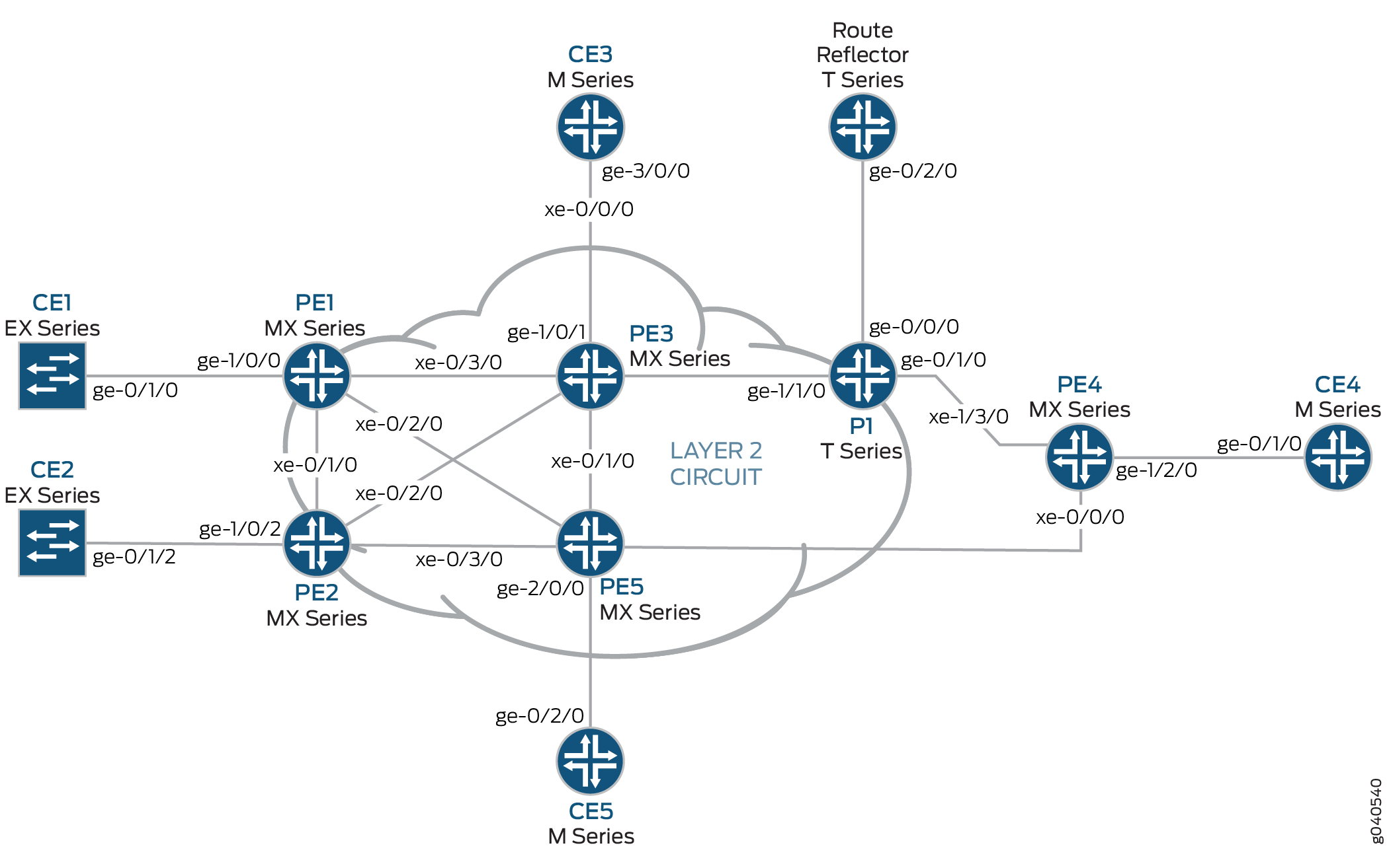
Figure 1 shows the physical topology of a Layer 2 VPN-to-Layer 3 VPN interconnection.
The logical topology of a Layer 2 VPN-to-Layer 3 VPN interconnection is shown in Figure 2.
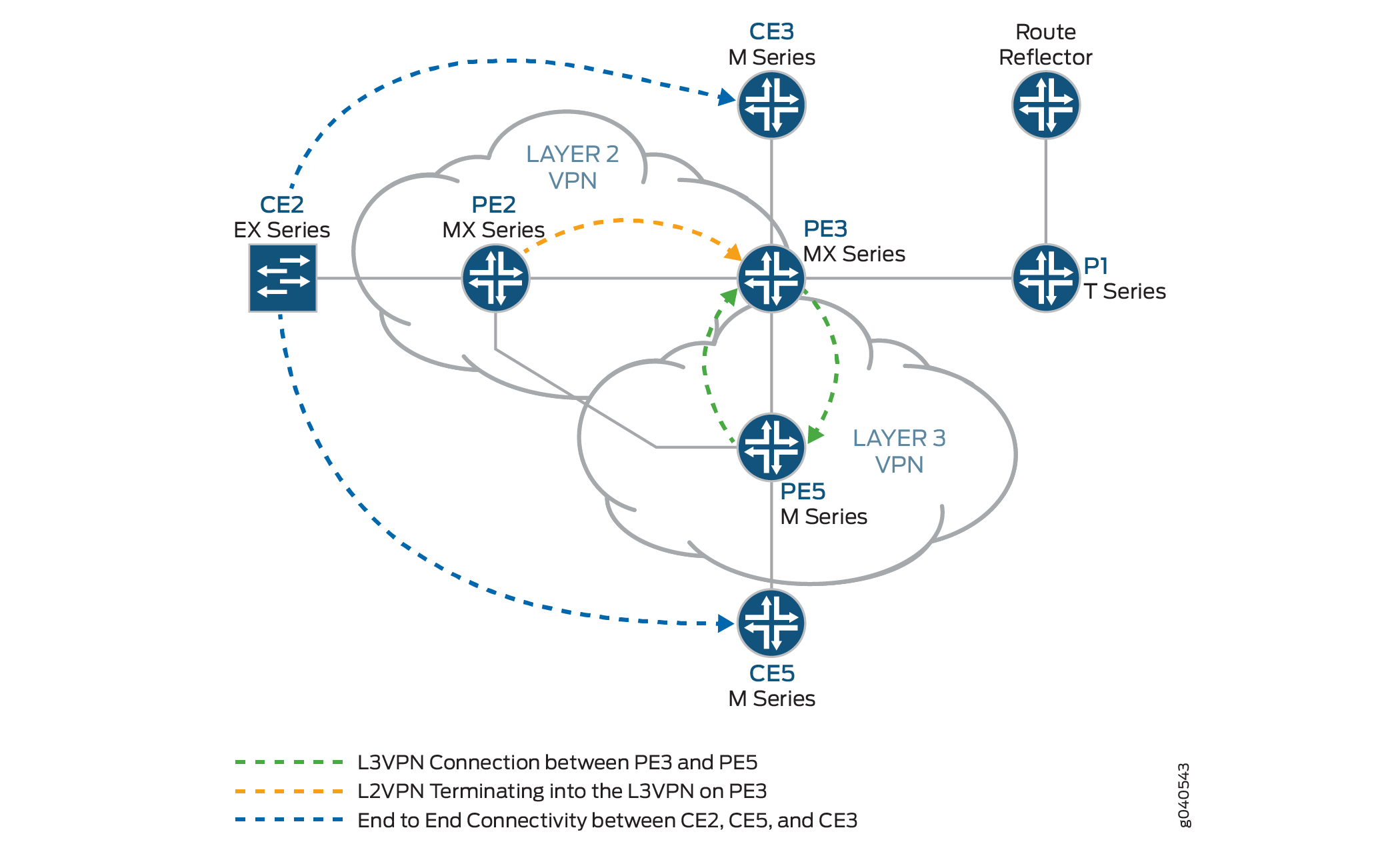
The following definitions describe the meaning of the device abbreviations used in Figure 1 and Figure 2.
Customer edge (CE) device—A device at the customer premises that provides access to the service provider’s VPN over a data link to one or more provider edge (PE) routers.
Typically the CE device is an IP router that establishes an adjacency with its directly connected PE routers. After the adjacency is established, the CE router advertises the site’s local VPN routes to the PE router and learns remote VPN routes from the PE router.
Provider edge (PE) device—A device, or set of devices, at the edge of the provider network that presents the provider's view of the customer site.
PE routers exchange routing information with CE routers. PE routers are aware of the VPNs that connect through them, and PE routers maintain VPN state. A PE router is only required to maintain VPN routes for those VPNs to which it is directly attached. After learning local VPN routes from CE routers, a PE router exchanges VPN routing information with other PE routers using IBGP. Finally, when using MPLS to forward VPN data traffic across the provider’s backbone, the ingress PE router functions as the ingress label-switching router (LSR) and the egress PE router functions as the egress LSR.
Provider (P) device—A device that operates inside the provider's core network and does not directly interface to any CE.
Although the P device is a key part of implementing VPNs for the service provider’s customers and may provide routing for many provider-operated tunnels that belong to different VPNs, it is not itself VPN-aware and does not maintain VPN state. Its principal role is allowing the service provider to scale its VPN offerings, for example, by acting as an aggregation point for multiple PE routers.
P routers function as MPLS transit LSRs when forwarding VPN data traffic between PE routers. P routers are required only to maintain routes to the provider’s PE routers; they are not required to maintain specific VPN routing information for each customer site.
Configuration
To interconnect a Layer 2 VPN with a Layer 3 VPN, perform these tasks:
Configuring the Base Protocols and Interfaces
Step-by-Step Procedure
On each PE and P router, configure OSPF with traffic engineering extensions on all interfaces. Disable OSPF on the fxp0.0 interface.
[edit protocols]
ospf {
    traffic-engineering;
    area 0.0.0.0 {
        interface all;
        interface fxp0.0 {
            disable;
        }
    }
}
On all the core routers, enable MPLS on all interfaces. Disable MPLS on the fxp0.0 interface.
[edit protocols]
mpls {
    interface all;
    interface fxp0.0 {
        disable;
    }
}
On all the core routers, create an internal BGP peer group and specify the route reflector address (192.0.2.7) as the neighbor. Also enable BGP to carry Layer 2 VPLS network layer reachability information (NLRI) messages for this peer group by including the
signalingstatement at the[edit protocols bgp group group-name family l2vpn]hierarchy level.[edit protocols] bgp { group RR { type internal; local-address 192.0.2.2; family l2vpn { signaling; } neighbor 192.0.2.7; } }On Router PE3, create an internal BGP peer group and specify the route reflector IP address (192.0.2.7) as the neighbor. Enable BGP to carry Layer 2 VPLS NLRI messages for this peer group and enable the processing of VPN-IPv4 addresses by including the
unicaststatement at the[edit protocols bgp group group-name family inet-vpn]hierarchy level.[edit protocols] bgp { group RR { type internal; local-address 192.0.2.3; family inet-vpn { unicast; } family l2vpn { signaling; } neighbor 192.0.2.7; } }For the Layer 3 VPN domain on Router PE3 and Router PE5, enable RSVP on all interfaces. Disable RSVP on the fxp0.0 interface.
[edit protocols]
rsvp {
    interface all;
    interface fxp0.0 {
        disable;
    }
}
On Router PE3 and Router PE5, create label-switched paths (LSPs) to the route reflector and the other PE routers. The following example shows the configuration on Router PE5.
[edit protocols]
mpls {
    label-switched-path to-RR {
        to 192.0.2.7;
    }
    label-switched-path to-PE2 {
        to 192.0.2.2;
    }
    label-switched-path to-PE3 {
        to 192.0.2.3;
    }
    label-switched-path to-PE4 {
        to 192.0.2.4;
    }
    label-switched-path to-PE1 {
        to 192.0.2.1;
    }
}
On Routers PE1, PE2, PE3, and PE5, configure the core interfaces with an IPv4 address and enable the MPLS address family. The following example shows the configuration of the xe-0/1/0 interface on Router PE2.
[edit]
interfaces {
    xe-0/1/0 {
        unit 0 {
            family inet {
                address 10.10.2.2/30;
            }
            family mpls;
        }
    }
}
On Router PE2 and Router PE3, configure LDP for the Layer 2 VPN MPLS signaling protocol for all interfaces. Disable LDP on the fxp0.0 interface. (RSVP can also be used.)
[edit protocols]
ldp {
    interface all;
    interface fxp0.0 {
        disable;
    }
}
On the route reflector, create an internal BGP peer group and specify the PE routers IP addresses as the neighbors.
[edit]
protocols {
    bgp {
        group RR {
            type internal;
            local-address 192.0.2.7;
            family inet {
                unicast;
            }
            family inet-vpn {
                unicast;
            }
            family l2vpn {
                signaling;
            }
            cluster 192.0.2.7;
            neighbor 192.0.2.1;
            neighbor 192.0.2.2;
            neighbor 192.0.2.4;
            neighbor 192.0.2.5;
            neighbor 192.0.2.3;
        }
    }
}
On the route reflector, configure MPLS LSPs towards Routers PE3 and PE5 to resolve the BGP next hops from inet.3 routing table.
[edit]
protocols {
    mpls {
        label-switched-path to-pe3 {
            to 192.0.2.3;
        }

        label-switched-path to-pe5 {
            to 192.0.2.5;
        }
        interface all;
    }
}
Configuring the VPN Interfaces
Step-by-Step Procedure
Router PE2 is one end of the Layer 2 VPN. Router PE3 is performing the Layer 2 VPN stitching between the Layer 2 VPN and the Layer 3 VPN. Router PE3 uses the logical tunnel interface (lt interface) configured with different logical interface units applied under two different Layer 2 VPN instances. The packet is looped though the lt interface configured on Router PE3. The configuration of Router PE5 contains the PE-CE interface.
On Router PE2, configure the ge-1/0/2 interface encapsulation. Include the encapsulation statement and specify the
ethernet-cccoption (vlan-cccencapsulation is also supported) at the[edit interfaces ge-1/0/2]hierarchy level. The encapsulation should be the same in a whole Layer 2 VPN domain (Routers PE2 and PE3). Also, configure interface lo0.[edit] interfaces { ge-1/0/2 { encapsulation ethernet-ccc; unit 0; } lo0 { unit 0 { family inet { address 192.0.2.2/24; } } } }On Router PE2, configure the routing instance at the [
edit routing-instances]hierarchy level. Also, configure the Layer 2 VPN protocol at the [edit routing-instances routing-instances-name protocols]hierarchy level. Configure the remote site ID as 3. Site ID 3 represents Router PE3 (Hub-PE). The Layer 2 VPN is using LDP as the signaling protocol. Be aware that in the following example, both the routing instance and the protocol are namedl2vpn.[edit] routing-instances {l2vpn{ # routing instance instance-type l2vpn; interface ge-1/0/2.0; route-distinguisher 65000:2; vrf-target target:65000:2; protocols {l2vpn{ # protocol encapsulation-type ethernet; site CE2 { site-identifier 2; interface ge-1/0/2.0 { remote-site-id 3; } } } } } }On Router PE5, configure the Gigabit Ethernet interface for the PE-CE link
ge-2/0/0and configure thelo0interface.[edit interfaces] ge-2/0/0 { unit 0 { family inet { address 198.51.100.8/24; } } } lo0 { unit 0 { } }On Router PE5, configure the Layer 3 VPN routing instance (
L3VPN) at the[edit routing-instances]hierarchy level. Also configure BGP at the[edit routing-instances L3VPN protocols]hierarchy level.[edit] routing-instances { L3VPN { instance-type vrf; interface ge-2/0/0.0; route-distinguisher 65000:5; vrf-target target:65000:2; vrf-table-label; protocols { bgp { group ce5 { neighbor 198.51.100.2 { peer-as 200; } } } } } }In an MX Series router, such as Router PE3, you must create the tunnel services interface to be used for tunnel services. To create the tunnel service interface, include the
bandwidthstatement and specify the amount of bandwidth to reserve for tunnel services in gigabits per second at the[edit chassis fpc slot-number pic slot-number tunnel-services]hierarchy level.[edit] chassis { dump-on-panic; fpc 1 { pic 1 { tunnel-services { bandwidth 1g; } } } }On Router PE3, configure the Gigabit Ethernet interface.
Include the
addressstatement at the[edit interfaces ge-1/0/1.0 family inet]hierarchy level and specify198.51.100.9/24as the IP address.[edit] interfaces { ge-1/0/1 { unit 0 { family inet { address 198.51.100.9/24; } } } }On Router PE3, configure the
lt-1/1/10.0logical tunnel interface at the[edit interfaces lt-1/1/10 unit 0]hierarchy level. Router PE3 is the router that is stitching the Layer 2 VPN to the Layer 3 VPN using the logical tunnel interface. The configuration of the peer unit interfaces is what makes the interconnection.To configure the interface, include the
encapsulationstatement and specify theethernet-cccoption. Include thepeer-unitstatement and specify the logical interface unit1as the peer tunnel interface. Include thefamilystatement and specify thecccoption.[edit] interfaces { lt-1/1/10 { unit 0 { encapsulation ethernet-ccc; peer-unit 1; family ccc; } } }On Router PE3, configure the
lt-1/1/10.1logical tunnel interface at the[edit interfaces lt-1/1/10 unit 1]hierarchy level.To configure the interface, include the
encapsulationstatement and specify theethernetoption. Include thepeer-unitstatement and specify the logical interface unit0as the peer tunnel interface. Include thefamilystatement and specify theinetoption. Include theaddressstatement at the[edit interfaces lt-1/1/10 unit 0]hierarchy level and specify198.51.100.7/24as the IPv4 address.[edit] interfaces { lt-1/1/10 { unit 1 { encapsulation ethernet; peer-unit 0; family inet { address 198.51.100.7/24; } } } }On Router PE3, add the
ltinterface unit 1 to the routing instance at the[edit routing-instances L3VPN]hierarchy level. Configure the instance type asvrfwithltpeer-unit 1 as a PE-CE interface to terminate the Layer 2 VPN on Router PE2 into the Layer 3 VPN on Router PE3.[edit] routing-instances { L3VPN { instance-type vrf; interface ge-1/0/1.0; interface lt-1/1/10.1; route-distinguisher 65000:33; vrf-target target:65000:2; vrf-table-label; protocols { bgp { export direct; group ce3 { neighbor 198.51.100.10 { peer-as 100; } } } } } }On Router PE3, add the
ltinterface unit 0 to the routing instance at the[edit routing-instances protocols l2vpn]hierarchy level. Also configure the same vrf target for the Layer 2 VPN and Layer 3 VPN routing instances, so that the routes can be leaked between the instances. The example configuration in the previous step shows the vrf target for theL3VPNrouting instance. The following example shows the vrf target for thel2vpnrouting instance.[edit] routing-instances { l2vpn { instance-type l2vpn; interface lt-1/1/10.0; route-distinguisher 65000:3; vrf-target target:65000:2; protocols { l2vpn { encapsulation-type ethernet; site CE3 { site-identifier 3; interface lt-1/1/10.0 { remote-site-id 2; } } } } } }On Router PE3, configure the
policy-statementstatement to export the routes learned from the directly connectedltinterface unit 1 to all the CE routers for connectivity, if needed.[edit] policy-options { policy-statement direct { term 1 { from protocol direct; then accept; } } }
Results
The following output shows the full configuration of Router PE2:
Router PE2
interfaces {
    xe-0/1/0 {
        unit 0 {
            family inet {
                address 10.10.2.2/30;
            }
            family mpls;
        }
    }
    xe-0/2/0 {
        unit 0 {
            family inet {
                address 10.10.5.1/30;
            }
            family mpls;
        }
    }
    xe-0/3/0 {
        unit 0 {
            family inet {
                address 10.10.4.1/30;
            }
            family mpls;
        }
    }
    ge-1/0/2 {
        encapsulation ethernet-ccc;
        unit 0;
    }
    fxp0 {
        apply-groups [ re0 re1 ];
    }
    lo0 {
        unit 0 {
            family inet {
                address 192.0.2.2/24;
            }
        }
    }
}
routing-options {
    static {
        route 172.0.0.0/8 next-hop 172.19.59.1;
    }
    autonomous-system 65000;
}
protocols {
    mpls {
        interface all;
        interface fxp0.0 {
            disable;
        }
    }
    bgp {
        group RR {
            type internal;
            local-address 192.0.2.2;
            family l2vpn {
                signaling;
            }
            neighbor 192.0.2.7;
        }
    }
    ospf {
        traffic-engineering;
        area 0.0.0.0 {
            interface all;
            interface fxp0.0 {
                disable;
            }
        }
    }
    ldp {
        interface all;
        interface fxp0.0 {
            disable;
        }
    }
}
routing-instances {
    l2vpn {
        instance-type l2vpn;
        interface ge-1/0/2.0;
        route-distinguisher 65000:2;
        vrf-target target:65000:2;
        protocols {
            l2vpn {
                encapsulation-type ethernet;
                site CE2 {
                    site-identifier 2;
                    interface ge-1/0/2.0 {
                        remote-site-id 3;
                    }
                }
            }
        }
    }
}
The following output shows the final configuration of Router PE5:
Router PE5
interfaces {
    ge-0/0/0 {
        unit 0 {
            family inet {
                address 10.10.4.2/30;
            }
            family mpls;
        }
    }
    xe-0/1/0 {
        unit 0 {
            family inet {
                address 10.10.6.2/30;
            }
            family mpls;
        }
    }
    ge-1/0/0 {
        unit 0 {
            family inet {
                address 10.10.9.1/30;
            }
            family mpls;
        }
    }
    xe-1/1/0 {
        unit 0 {
            family inet {
                address 10.10.3.2/30;
            }
            family mpls;
        }
    }
    ge-2/0/0 {
        unit 0 {
            family inet {
                address 198.51.100.8/24;
            }
        }
    }
    lo0 {
        unit 0 {
            family inet {
                address 192.0.2.5/24;
            }
        }
    }
}
routing-options {
    static {
        route 172.0.0.0/8 next-hop 172.19.59.1;
    }
    autonomous-system 65000;
}
protocols {
    rsvp {
        interface all {
            link-protection;
        }
        interface fxp0.0 {
            disable;
        }
    }
    mpls {
        label-switched-path to-RR {
            to 192.0.2.7;
        }
        label-switched-path to-PE2 {
            to 192.0.2.2;
        }
        label-switched-path to-PE3 {
            to 192.0.2.3;
        }
        label-switched-path to-PE4 {
            to 192.0.2.4;
        }
        label-switched-path to-PE1 {
            to 192.0.2.1;
        }
        interface all;
        interface fxp0.0 {
            disable;
        }

    }
    bgp {
        group to-rr {
            type internal;
            local-address 192.0.2.5;
            family inet-vpn {
                unicast;
            }
            family l2vpn {
                signaling;
            }
            neighbor 192.0.2.7;
        }
    }
    ospf {
        traffic-engineering;
        area 0.0.0.0 {
            interface all;
            interface fxp0.0 {
                disable;
            }
        }
    }
    ldp {
        interface all;
        interface fxp0.0 {
            disable;
        }
    }
}
routing-instances {
    L3VPN {
        instance-type vrf;
        interface ge-2/0/0.0;
        route-distinguisher 65000:5;
        vrf-target target:65000:2;
        vrf-table-label;
        protocols {
            bgp {
                group ce5 {
                    neighbor 198.51.100.2 {
                        peer-as 200;
                    }
                }
            }
        }
    }
}
The following output shows the final configuration of Router PE3:
Router PE3
chassis {
    dump-on-panic;
    fpc 1 {
        pic 1 {
            tunnel-services {
                bandwidth 1g;
            }
        }
    }
    network-services ip;
}
interfaces {
    ge-1/0/1 {
        unit 0 {
            family inet {
                address 198.51.100.9/24;
            }
        }
    }
    lt-1/1/10 {
        unit 0 {
            encapsulation ethernet-ccc;
            peer-unit 1;
            family ccc;
        }
        unit 1 {
            encapsulation ethernet;
            peer-unit 0;
            family inet {
                address 198.51.100.7/24;
            }
        }
    }
    xe-2/0/0 {
        unit 0 {
            family inet {
                address 10.10.20.2/30;
            }
            family mpls;
        }
    }
    xe-2/1/0 {
        unit 0 {
            family inet {
                address 10.10.6.1/30;
            }
            family mpls;
        }
    }
    xe-2/2/0 {
        unit 0 {
            family inet {
                address 10.10.5.2/30;
            }
            family mpls;
        }
    }
    xe-2/3/0 {
        unit 0 {
            family inet {
                address 10.10.1.2/30;
            }
            family mpls;
        }
    }
    lo0 {
        unit 0 {
            family inet {
                address 192.0.2.3/24;
            }
        }
    }
}
routing-options {
    static {
        route 172.0.0.0/8 next-hop 172.19.59.1;
    }
    autonomous-system 65000;
}
protocols {
    rsvp {
        interface all;
        interface fxp0.0 {
            disable;
        }
    }
    mpls {
        label-switched-path to-RR {
            to 192.0.2.7;
        }
        label-switched-path to-PE2 {
            to 192.0.2.2;
        }
        label-switched-path to-PE5 {
            to 192.0.2.5;
        }
        label-switched-path to-PE4 {
            to 192.0.2.4;
        }
        label-switched-path to-PE1 {
            to 192.0.2.1;
        }
        interface all;
        interface fxp0.0 {
            disable;
        }
    }
    bgp {
        group RR {
            type internal;
            local-address 192.0.2.3;
            family inet-vpn {
                unicast;
            }
            family l2vpn {
                signaling;
            }
            neighbor 192.0.2.7;
        }
    }
    ospf {
        traffic-engineering;
        area 0.0.0.0 {
            interface all;
            interface fxp0.0 {
                disable;
            }
        }
    }
    ldp {
        interface all;
        interface fxp0.0 {
            disable;
        }
    }
}
policy-options {
    policy-statement direct {
        term 1 {
            from protocol direct;
            then accept;
        }
    }
}
routing-instances {
    L3VPN {
        instance-type vrf;
        interface ge-1/0/1.0;
        interface lt-1/1/10.1;
        route-distinguisher 65000:33;
        vrf-target target:65000:2;
        vrf-table-label;
        protocols {
            bgp {
                export direct;
                group ce3 {
                    neighbor 198.51.100.10 {
                        peer-as 100;
                    }
                }
            }
        }
    }
    l2vpn {
        instance-type l2vpn;
        interface lt-1/1/10.0;
        route-distinguisher 65000:3;
        vrf-target target:65000:2;
        protocols {
            l2vpn {
                encapsulation-type ethernet;
                site CE3 {
                    site-identifier 3;
                    interface lt-1/1/10.0 {
                        remote-site-id 2;
                    }
                }
            }
        }
    }
}
Verification
Verify the Layer 2 VPN-to-Layer 3 VPN interconnection:
- Verifying Router PE2 VPN Interface
- Verifying Router PE3 VPN Interface
- Verifying End-to-End connectivity from Router CE2 to Router CE5 and Router CE3
Verifying Router PE2 VPN Interface
Purpose
Check that the Layer 2 VPN is up and working at the Router PE2 interface and that all the routes are there.
Action
Use the
show l2vpn connectionscommand to verify that the connection site ID is 3 for Router PE3 and that the status isUp.user@PE2> show l2vpn connections Layer-2 VPN connections: Legend for connection status (St) EI -- encapsulation invalid NC -- interface encapsulation not CCC/TCC/VPLS EM -- encapsulation mismatch WE -- interface and instance encaps not same VC-Dn -- Virtual circuit down NP -- interface hardware not present CM -- control-word mismatch -> -- only outbound connection is up CN -- circuit not provisioned <- -- only inbound connection is up OR -- out of range Up -- operational OL -- no outgoing label Dn -- down LD -- local site signaled down CF -- call admission control failure RD -- remote site signaled down SC -- local and remote site ID collision LN -- local site not designated LM -- local site ID not minimum designated RN -- remote site not designated RM -- remote site ID not minimum designated XX -- unknown connection status IL -- no incoming label MM -- MTU mismatch MI -- Mesh-Group ID not available BK -- Backup connection ST -- Standby connection PF -- Profile parse failure PB -- Profile busy RS -- remote site standby Legend for interface status Up -- operational Dn -- down Instance: l2vpn Local site: CE2 (2) connection-site Type St Time last up # Up trans 3 rmt Up Jan 7 14:14:37 2010 1 Remote PE: 192.0.2.3, Negotiated control-word: Yes (Null) Incoming label: 800000, Outgoing label: 800001 Local interface: ge-1/0/2.0, Status: Up, Encapsulation: ETHERNETUse the
show route tablecommand to verify that the Layer 2 VPN route is present and that there is a next hop of10.10.5.2through thexe-0/2/0.0interface. The following output verifies that the Layer 2 VPN routes are present in the l2vpn.l2vpn.0 table. Similar output should be displayed for Router PE3.user@PE2> show route table l2vpn.l2vpn.0 l2vpn.l2vpn.0: 2 destinations, 2 routes (2 active, 0 holddown, 0 hidden) + = Active Route, - = Last Active, * = Both 65000:2:2:3/96 *[L2VPN/170/-101] 02:40:35, metric2 1 Indirect 65000:3:3:1/96 *[BGP/170] 02:40:35, localpref 100, from 192.0.2.7 AS path: I > to 10.10.5.2 via xe-0/2/0.0Verify that Router PE2 has a Layer 2 VPN MPLS label pointing to the LDP label to Router PE3 in both directions (PUSH and POP).
user@PE2> show route table mpls.0
 mpls.0: 13 destinations, 13 routes (13 active, 0 holddown, 0 hidden)
+ = Active Route, - = Last Active, * = Both

0                  *[MPLS/0] 1w3d 08:57:41, metric 1
                      Receive
1                  *[MPLS/0] 1w3d 08:57:41, metric 1
                      Receive
2                  *[MPLS/0] 1w3d 08:57:41, metric 1
                      Receive
300560             *[LDP/9] 19:45:53, metric 1
                    > to 10.10.2.1 via xe-0/1/0.0, Pop
300560(S=0)        *[LDP/9] 19:45:53, metric 1
                    > to 10.10.2.1 via xe-0/1/0.0, Pop
301008             *[LDP/9] 19:45:53, metric 1
                    > to 10.10.4.2 via xe-0/3/0.0, Swap 299856
301536             *[LDP/9] 19:45:53, metric 1
                    > to 10.10.4.2 via xe-0/3/0.0, Pop
301536(S=0)        *[LDP/9] 19:45:53, metric 1
                    > to 10.10.4.2 via xe-0/3/0.0, Pop
301712             *[LDP/9] 16:14:52, metric 1
                    > to 10.10.5.2 via xe-0/2/0.0, Swap 315184
301728             *[LDP/9] 16:14:52, metric 1
                    > to 10.10.5.2 via xe-0/2/0.0, Pop
301728(S=0)        *[LDP/9] 16:14:52, metric 1
                    > to 10.10.5.2 via xe-0/2/0.0, Pop
800000             *[L2VPN/7] 02:40:35
                    > via ge-1/0/2.0, Pop       Offset: 4
ge-1/0/2.0         *[L2VPN/7] 02:40:35, metric2 1
                    > to 10.10.5.2 via xe-0/2/0.0, Push 800001 Offset: -4
Meaning
The l2vpn routing instance is up at interface ge-1/0/2 and the Layer 2 VPN route is shown in table l2vpn.l2vpn.0.
Table mpls.0 shows the Layer 2 VPN routes used to forward
the traffic using an LDP label.
Verifying Router PE3 VPN Interface
Purpose
Check that the Layer 2 VPN connection from Router PE2
and Router PE3 is Up and working.
Action
Verify that the BGP session with the route reflector for the family
l2vpn-signalingand the familyinet-vpnis established.user@PE3> show bgp summary Groups: 2 Peers: 2 Down peers: 0 Table Tot Paths Act Paths Suppressed History Damp State Pending bgp.l2vpn.0 1 1 0 0 0 0 bgp.L3VPN.0 1 1 0 0 0 0 Peer AS InPkt OutPkt OutQ Flaps Last Up/Dwn State|#Active /Received/Accepted/Damped... 192.0.2.7 65000 2063 2084 0 1 15:35:16 Establ bgp.l2vpn.0: 1/1/1/0 bgp.L3VPN.0: 1/1/1/0 L3VPN.inet.0: 1/1/1/0 l2vpn.l2vpn.0: 1/1/1/0
The following output verifies the Layer 2 VPN route and the label associated with it.
user@PE3> show route table l2vpn.l2vpn.0 detail
l2vpn.l2vpn.0: 2 destinations, 2 routes (2 active, 0 holddown, 0 hidden)
65000:2:2:3/96 (1 entry, 1 announced)
        *BGP    Preference: 170/-101
                Route Distinguisher: 65000:2
                Next hop type: Indirect
                Next-hop reference count: 4
                Source: 192.0.2.7
                Protocol next hop: 192.0.2.2
                Indirect next hop: 2 no-forward
                State: <Secondary Active Int Ext>
                Local AS: 65000 Peer AS: 65000
                Age: 2:45:52    Metric2: 1
                Task: BGP_65000.192.0.2.7+60585
                Announcement bits (1): 0-l2vpn-l2vpn
                AS path: I (Originator) Cluster list:  192.0.2.7
                AS path:  Originator ID: 192.0.2.2
                Communities: target:65000:2 Layer2-info: encaps:ETHERNET, control flags:Control-Word, mtu: 0, site preference: 100  Accepted
                Label-base: 800000, range: 2, status-vector: 0x0
                Localpref: 100
                Router ID: 192.0.2.7
                Primary Routing Table bgp.l2vpn.0
The following output show the L2VPN MPLS.0 route in the mpls.0 route table.
user@PE3> show route table mpls.0
mpls.0: 21 destinations, 21 routes (21 active, 0 holddown, 0 hidden)
+ = Active Route, - = Last Active, * = Both

0                  *[MPLS/0] 1w3d 09:05:41, metric 1
                      Receive
1                  *[MPLS/0] 1w3d 09:05:41, metric 1
                      Receive
2                  *[MPLS/0] 1w3d 09:05:41, metric 1
                      Receive
16                 *[VPN/0] 15:59:24
                      to table L3VPN.inet.0, Pop
315184             *[LDP/9] 16:21:53, metric 1
                    > to 10.10.20.1 via xe-2/0/0.0, Pop
315184(S=0)        *[LDP/9] 16:21:53, metric 1
                    > to 10.10.20.1 via xe-2/0/0.0, Pop
315200             *[LDP/9] 01:13:44, metric 1
                      to 10.10.20.1 via xe-2/0/0.0, Swap 625297
                    > to 10.10.6.2 via xe-2/1/0.0, Swap 299856
315216             *[LDP/9] 16:21:53, metric 1
                    > to 10.10.6.2 via xe-2/1/0.0, Pop
315216(S=0)        *[LDP/9] 16:21:53, metric 1
                    > to 10.10.6.2 via xe-2/1/0.0, Pop
315232             *[LDP/9] 16:21:45, metric 1
                    > to 10.10.1.1 via xe-2/3/0.0, Pop
315232(S=0)        *[LDP/9] 16:21:45, metric 1
                    > to 10.10.1.1 via xe-2/3/0.0, Pop
315248             *[LDP/9] 16:21:53, metric 1
                    > to 10.10.5.1 via xe-2/2/0.0, Pop
315248(S=0)        *[LDP/9] 16:21:53, metric 1
                    > to 10.10.5.1 via xe-2/2/0.0, Pop
315312             *[RSVP/7] 15:02:40, metric 1
                    > to 10.10.6.2 via xe-2/1/0.0, label-switched-path to-pe5
315312(S=0)        *[RSVP/7] 15:02:40, metric 1
                    > to 10.10.6.2 via xe-2/1/0.0, label-switched-path to-pe5
315328             *[RSVP/7] 15:02:40, metric 1
                    > to 10.10.20.1 via xe-2/0/0.0, label-switched-path to-RR
315360             *[RSVP/7] 15:02:40, metric 1
                    > to 10.10.20.1 via xe-2/0/0.0, label-switched-path to-RR
316272             *[RSVP/7] 01:13:27, metric 1
                    > to 10.10.6.2 via xe-2/1/0.0, label-switched-path Bypass->10.10.9.1
316272(S=0)        *[RSVP/7] 01:13:27, metric 1
                    > to 10.10.6.2 via xe-2/1/0.0, label-switched-path Bypass->10.10.9.1
800001             *[L2VPN/7] 02:47:33
                    > via lt-1/1/10.0, Pop       Offset: 4
lt-1/1/10.0        *[L2VPN/7] 02:47:33, metric2 1
                    > to 10.10.5.1 via xe-2/2/0.0, Push 800000 Offset: -4
Use the
show route table mpls.0command with thedetailoption to see the BGP attributes of the route such as next-hop type and label operations.user@PE5> show route table mpls.0 detail lt-1/1/10.0 (1 entry, 1 announced) *L2VPN Preference: 7 Next hop type: Indirect Next-hop reference count: 2 Next hop type: Router, Next hop index: 607 Next hop: 10.10.5.1 via xe-2/2/0.0, selected Label operation: Push 800000 Offset: -4 Protocol next hop: 192.0.2.2 Push 800000 Offset: -4 Indirect next hop: 8cae0a0 1048574 State: <Active Int> Age: 2:46:34 Metric2: 1 Task: Common L2 VC Announcement bits (2): 0-KRT 2-Common L2 VC AS path: I Communities: target:65000:2 Layer2-info: encaps:ETHERNET, control flags:Control-Word, mtu: 0, site preference: 100
Verifying End-to-End connectivity from Router CE2 to Router CE5 and Router CE3
Purpose
Check the connectivity between Routers CE2, CE3, and CE5.
Action
Ping the Router CE3 IP address from Router CE2.
user@CE2> ping 198.51.100.10 # CE3 IP address
PING 198.51.100.10 (198.51.100.10): 56 data bytes
64 bytes from 198.51.100.10: icmp_seq=0 ttl=63 time=0.708 ms
64 bytes from 198.51.100.10: icmp_seq=1 ttl=63 time=0.610 ms
Ping the Router CE5 IP address from Router CE2.
user@CE2> ping 198.51.100.2 # CE5 IP address
PING 198.51.100.2 (198.51.100.2): 56 data bytes
64 bytes from 198.51.100.2: icmp_seq=0 ttl=62 time=0.995 ms
64 bytes from 198.51.100.2: icmp_seq=1 ttl=62 time=1.005 ms