Connecting Layer 3 VPNs to Layer 2 Circuits
Applications for Interconnecting a Layer 2 Circuit with a Layer 3 VPN
MPLS-based Layer 2 services are growing in demand among enterprise and service providers. This creates new challenges related to interoperability between Layer 2 and Layer 3 services for service providers who want to provide end-to-end value-added services. There are various reasons to stitch different Layer 2 services to one another and to Layer 3 services. For example, to expand the service offerings and to expand geographically. The Junos OS has various features to address the needs of the service provider.
You can enable pseudowire services and configure a pseduowire service interface as an access point for interconnecting layer 2 circuits to layer 3 VPNs. For more information, see Pseudowire Subscriber Logical Interfaces Overview.
Interconnecting a Layer 2 Circuit with a Layer 3 VPN provides the following benefits:
Interconnecting a Layer 2 Circuit with a Layer 3 VPN enables the sharing of a service provider's core network infrastructure between IP and Layer 2 circuit services, reducing the cost of providing those services. A Layer 2 MPLS circuit allows service providers to create a Layer 2 circuit service over an existing IP and MPLS backbone.
Service providers do not have to invest in separate Layer 2 equipment to provide Layer 2 circuit service. A service provider can configure a provider edge router to run any Layer 3 protocol in addition to the Layer 2 protocols. Customers who prefer to maintain control over most of the administration of their own networks want Layer 2 circuit connections with their service provider instead of a Layer 3 VPN connection.
Example: Interconnecting a Layer 2 Circuit with a Layer 3 VPN
This example provides a step-by-step procedure and commands for configuring and verifying a Layer 2 circuit to Layer 3 VPN interconnection. It contains the following sections:
- Requirements
- Overview and Topology
- Configuration
- Verifying the Layer 2 Circuit to Layer 3 VPN Interconnection
Requirements
This example uses the following hardware and software components:
Junos OS Release 9.3 or later
3 MX Series 5G Universal Routing Platforms
1 M Series Multiservice Edge Router
1 T Series Core Router
1 EX Series Ethernet Switch
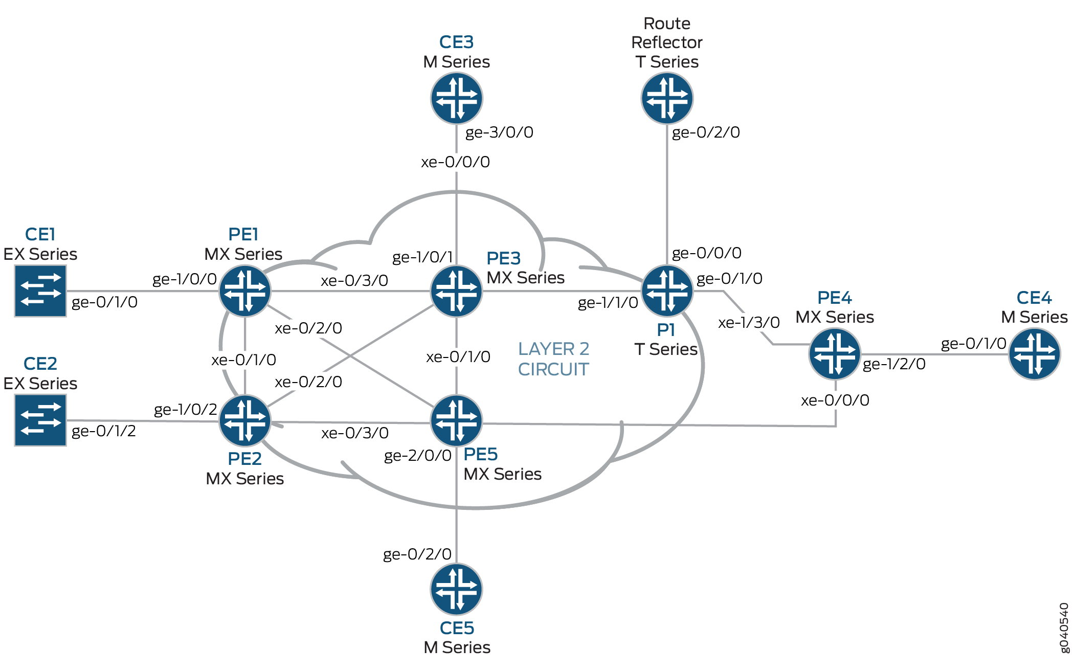
Overview and Topology
The physical topology of a Layer 2 circuit to Layer 3 VPN interconnection is shown in Figure 1.
The logical topology of a Layer 2 circuit to Layer 3 VPN interconnection is shown in Figure 2.
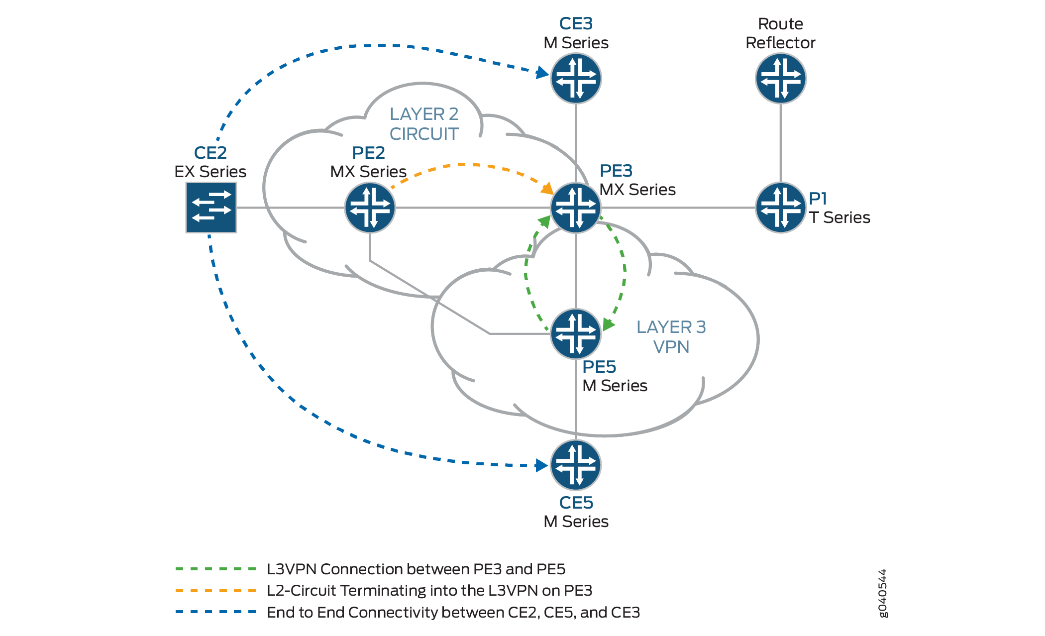
Topology
Configuration
In any configuration session, it is good practice to verify
periodically that the configuration can be committed using the commit check command.
In this example, the router being configured is identified using the following command prompts:
CE2identifies the customer edge 2 (CE2) routerPE1identifies the provider edge 1 (PE1) routerCE3identifies the customer edge 3 (CE3) routerPE3identifies the provider edge 3 (PE3) routerCE5identifies the customer edge 5 (CE5) routerPE5identifies the provider edge 5 (PE5) router
This example contains the following procedures:
- Configuring PE Router Customer-facing and Loopback Interfaces
- Configuring Core-facing Interfaces
- Configuring Protocols
- Configuring Routing Instances and Layer 2 Circuits
- Configuring the Route Reflector
- Interconnecting the Layer 2 Circuit with the Layer 3 VPN
Configuring PE Router Customer-facing and Loopback Interfaces
Step-by-Step Procedure
To begin building the interconnection, configure the interfaces on the PE routers. If your network contains provider (P) routers, configure the interfaces on the P routers also. This example shows the configuration for Router PE2, Router PE3, and Router PE5.
On Router PE2, configure the
ge-1/0/2interface encapsulation. To configure the interface encapsulation, include theencapsulationstatement and specify theethernet-cccoption (vlan-cccencapsulation is also supported). Configure thege-1/0/2.0logical interface family for circuit cross-connect functionality. To configure the logical interface family, include thefamilystatement and specify thecccoption. The encapsulation should be configured the same way for all routers in the Layer 2 circuit domain.[edit interfaces] ge-1/0/2 { encapsulation ethernet-ccc; unit 0 { family ccc; } }On Router PE2, configure the
lo0.0interface. Include thefamilystatement and specify theinetoption. Include theaddressstatement and specify192.0.2.2/24as the loopback IPv4 address.[edit interfaces] lo0 { unit 0 { family inet { address 192.0.2.2/24; } } }On Router PE3, configure the
ge-1/0/1interface. Include thefamilystatement and specify theinetoption. Include theaddressstatement and specify198.51.100.1/24as the interface address for this device.[edit interfaces] ge-1/0/1 { unit 0 { family inet { address 198.51.100.1/24; } } }On Router PE3, configure the
lo0.0loopback interface. Include thefamilystatement and specify theinetoption. Include theaddressstatement and specify192.0.2.3/24as the loopback IPv4 address for this router.[edit interfaces] lo0 { unit 0 { family inet { address 192.0.2.3/24; } } }On Router PE5, configure the
ge-2/0/0interface. Include thefamilystatement and specify theinetoption. Include theaddressstatement and specify198.51.100.8/24as the interface address.[edit interfaces] ge-2/0/0 { unit 0 { family inet { address 198.51.100.8/24; } } }On Router PE5, configure the
lo0.0interface. Include thefamilystatement and specify theinetoption. Include theaddressstatement and specify192.0.2.5/24as the loopback IPv4 address for this router.[edit interfaces] lo0 { unit 0 { family inet { address 192.0.2.5/24; } } }
Configuring Core-facing Interfaces
Step-by-Step Procedure
This procedure describes how to configure the core-facing
interfaces on the PE routers. This example does not include all the
core-facing interfaces shown in the physical topology illustration.
Enable the mpls and inet address families on
the core-facing interfaces.
On Router PE2, configure the
xe-0/2/0interface. Include thefamilystatement and specify theinetaddress family. Include theaddressstatement and specify10.10.5.1/30as the interface address. Include thefamilystatement and specify themplsaddress family.[edit interfaces] xe-0/2/0 { unit 0 { family inet { address 10.10.5.1/30; } family mpls; } }On Router PE3, configure the core-facing interfaces. Include the
familystatement and specify theinetaddress family. Include theaddressstatement and specify the IPv4 addresses shown in the example as the interface addresses. Include thefamilystatement and specify themplsaddress family. In the example, thexe-2/1/0interface is connected to Router PE5, and thexe-2/2/0interface is connected to Router PE2.[edit interfaces] xe-2/0/0 { unit 0 { family inet { address 10.10.20.2/30; } family mpls; } } xe-2/1/0 { unit 0 { family inet { address 10.10.6.1/30; } family mpls; } } xe-2/2/0 { unit 0 { family inet { address 10.10.5.2/30; } family mpls; } } xe-2/3/0 { unit 0 { family inet { address 10.10.1.2/30; } family mpls; } }On Router PE5, configure the
xe-0/1/0interface. Include thefamilystatement and specify theinetaddress family. Include theaddressstatement and specify10.10.6.2/30as the interface address. Include thefamilystatement and specify themplsaddress family.[edit interfaces] xe-0/1/0 { unit 0 { family inet { address 10.10.6.2/30; } family mpls; } }
Configuring Protocols
Step-by-Step Procedure
This procedure describes how to configure the protocols used in this example. If your network contains P routers, configure the interfaces on the P routers also.
On Router PE3, enable OSPF as the IGP. Enable the MPLS, LDP, and BGP protocols on all interfaces except
fxp.0. LDP is used as the signaling protocol for the Layer 2 circuit to Router PE2 . The following configuration snippet shows the protocol configuration for Router PE3:[edit] protocols { rsvp { interface all; interface fxp0.0 { disable; } } mpls { label-switched-path to-RR { to 192.0.2.7; } label-switched-path to-PE2 { to 192.0.2.2; } label-switched-path to-PE5 { to 192.0.2.5; } label-switched-path to-PE4 { to 192.0.2.4; } label-switched-path to-PE1 { to 192.0.2.1; } interface all; interface fxp0.0 { disable; } } bgp { group RR { type internal; local-address 192.0.2.3; family inet-vpn { unicast; } family l2vpn { signaling; } neighbor 192.0.2.7; } } ospf { traffic-engineering; area 0.0.0.0 { interface all; interface fxp0.0 { disable; } } } ldp { interface all; interface fxp0.0 { disable; } } }On Router PE2, configure the MPLS, OSPF, and LDP protocols.
[edit ]
protocols {
    mpls {
        interface all;
        interface fxp0.0 {
            disable;
        }
    }
    ospf {
        traffic-engineering;
        area 0.0.0.0 {
            interface all;
            interface fxp0.0 {
                disable;
            }
        }
    }
    ldp {
        interface all;
        interface fxp0.0 {
            disable;
        }
    }
}
On Router PE5, enable OSPF as the IGP. Enable the MPLS, RSVP, and BGP protocols on all interfaces except
fxp.0. Enable core-facing interfaces with themplsandinetaddress families.[edit] protocols { rsvp { interface all { link-protection; } interface fxp0.0 { disable; } } mpls { label-switched-path to-RR { to 192.0.2.7; } label-switched-path to-PE2 { to 192.0.2.2; } label-switched-path to-PE3 { to 192.0.2.3; } label-switched-path to-PE4 { to 192.0.2.4; } label-switched-path to-PE1 { to 192.0.2.1; } interface all; interface fxp0.0 { disable; } } bgp { group to-rr { type internal; local-address 192.0.2.5; family inet-vpn { unicast; } family l2vpn { signaling; } neighbor 192.0.2.7; } } ospf { traffic-engineering; area 0.0.0.0 { interface all; interface fxp0.0 { disable; } } } }
Configuring Routing Instances and Layer 2 Circuits
Step-by-Step Procedure
This procedure describes how to configure the Layer 2 circuit and the Layer 3 VPN.
On Router PE2, configure the Layer 2 circuit. Include the
l2circuitstatement. Include theneighborstatement and specify the loopback IPv4 address of Router PE3 as the neighbor. Include the interface statement and specifyge-1/0/2.0as the logical interface that is participating in the Layer 2 circuit. Include thevirtual-circuit-idstatement and specify100as the identifier. Include theno-control-wordstatement for equipment that does not support the control word.[edit ] protocols { l2circuit { neighbor 192.0.2.3 { interface ge-1/0/2.0 { virtual-circuit-id 100; no-control-word; } } } }On Router PE3, configure the Layer 2 circuit to Router PE2. Include the
l2circuitstatement. Include theneighborstatement and specify the loopback IPv4 address of Router PE2 as the neighbor. Include the interface statement and specifylt-1/1/10.0as the logical tunnel interface that is participating in the Layer 2 circuit. Include thevirtual-circuit-idstatement and specify100as the identifier. Include theno-control-wordstatement.[edit ] protocols { l2circuit { neighbor 192.0.2.2 { interface lt-1/1/10.0 { virtual-circuit-id 100; no-control-word; } } } }On Router PE3, configure the Layer 3 VPN (
L3VPN) routing instance to Router PE5 at the[edit routing-instances]hierarchy level. Also configure the BGP peer group at the[edit routing-instances L3VPN protocols]hierarchy level.[edit ] routing-instances { L3VPN { instance-type vrf; interface ge-1/0/1.0; interface lt-1/1/10.1; route-distinguisher 65000:33; vrf-target target:65000:2; vrf-table-label; protocols { bgp { export direct; group ce3 { neighbor 198.51.100.6{ peer-as 100; } } } } } }On Router PE5, configure the Layer 3 VPN routing instance (
L3VPN) at the[edit routing-instances]hierarchy level. Also configure the BGP peer group at the[edit routing-instances L3VPN protocols]hierarchy level.[edit ] routing-instances { L3VPN { instance-type vrf; interface ge-2/0/0.0; route-distinguisher 65000:5; vrf-target target:65000:2; vrf-table-label; protocols { bgp { group ce5 { neighbor 198.51.100.10 { peer-as 200; } } } } } }
Configuring the Route Reflector
Step-by-Step Procedure
Although a route reflector is not required to interconnect a Layer 2 circuit with a Layer 3 VPN, this examples uses a route reflector. This procedure shows the relevant portion of the route reflector configuration.
Configure the route reflector with RSVP, MPLS, BGP and OSPF. The route reflector is a BGP peer with the PE routers. Notice that the BGP peer group configuration includes the
familystatement and specifies theinet-vpnoption Theinet-vpnoption enables BGP to advertise network layer reachability information (NLRI) for the Layer 3 VPN routes. The configuration also includes thefamilystatement and specifies thel2vpnoption. Thel2vpnoption enables BGP to advertise NLRI for the Layer 2 circuit. Layer 2 circuits use the same internal BGP infrastructure as Layer 2 VPNs.[edit ] protocols { rsvp { interface all; interface fxp0.0 { disable; } } mpls { label-switched-path to-pe3 { to 192.0.2.3; } label-switched-path to-pe5 { to 192.0.2.5; } interface all; interface fxp0.0 { disable; } } bgp { group RR { type internal; local-address 192.0.2.7; family inet { unicast; } family inet-vpn { unicast; } family l2vpn { signaling; } cluster 192.0.2.7; neighbor 192.0.2.1; neighbor 192.0.2.2; neighbor 192.0.2.4; neighbor 192.0.2.5; neighbor 192.0.2.3; } } ospf { traffic-engineering; area 0.0.0.0 { interface all; interface fxp0.0 { disable; } } } }
Interconnecting the Layer 2 Circuit with the Layer 3 VPN
Step-by-Step Procedure
Before you can configure the logical tunnel interface in an MX Series router, you must create the tunnel services interface to be used for tunnel services.
Create the tunnel service interface on Router PE3. Include the
bandwidthstatement at the[edit chassis fpc slot-number pic slot-number tunnel-services]hierarchy level and specify the amount of bandwidth to reserve for tunnel services in gigabits per second.[edit chassis] fpc 1 { pic 1 { tunnel-services { bandwidth 1g; } } }On Router PE3, configure the
lt-1/1/10logical tunnel interface unit 0.Router PE3 is the router that is stitching the Layer 2 circuit to the Layer 3 VPN using the logical tunnel interface. The configuration of the peer unit interfaces is what makes the interconnection.
Include the
encapsulationstatement and specify theethernet-cccoption. Include thepeer-unitstatement and specify the logical interface unit1as the peer tunnel interface. Include thefamilystatement and specify thecccoption.Configure the
lt-1/1/10logical interface unit1withethernetencapsulation. Include thepeer-unitstatement and specify the logical interface unit0as the peer tunnel interface. Include thefamilystatement and specify theinetoption. Also include theaddressstatement and specify198.51.100.11/24as the IPv4 address of the interface.Note:The peering logical interfaces must belong to the same logical tunnel interface derived from the Tunnel Services PIC.
[edit interfaces]
lt-1/1/10 {
    unit 0 {
        encapsulation ethernet-ccc;
        peer-unit 1;
        family ccc;
    }
    unit 1 {
        encapsulation ethernet;
        peer-unit 0;
        family inet {
            address 198.51.100.11/24;
        }
    }
}
On each router, commit the configuration.
user@host> commit check
configuration check succeeds
user@host> commit
Verifying the Layer 2 Circuit to Layer 3 VPN Interconnection
To verify that the interconnection is working properly, perform these tasks:
- Verifying That the Layer 2 Circuit Connection to Router PE3 is Up
- Verifying LDP Neighbors and Targeted LDP LSPs on Router PE2
- Verifying the Layer 2 Circuit Routes on Router PE2
- Verifying That the Layer 2 Circuit Connection to Router PE2 is Up
- Verifying LDP Neighbors and Targeted LDP LSPs on Router PE3
- Verifying a BGP Peer Session with the Route Reflector on Router PE3
- Verifying the Layer 3 VPN Routes on Router PE3
- Verifying the Layer 2 Circuit Routes on Router PE3
- Verifying the MPLS Routes on Router PE3
- Verifying Traffic Flow Between Router CE2 and Router CE3
- Verifying Traffic Flow Between Router CE2 and Router CE5
Verifying That the Layer 2 Circuit Connection to Router PE3 is Up
Purpose
To verify that the Layer 2 circuit connection from
Router PE2 to Router PE3 is Up. To also document the incoming
and outgoing LDP labels and the circuit ID used by this Layer 2 circuit
connection.
Action
Verify that the Layer 2 circuit connection is up, using
the show l2circuit connections command.
user@PE2> show l2circuit connections
Legend for connection status (St)
EI -- encapsulation invalid      NP -- interface h/w not present
MM -- mtu mismatch               Dn -- down
EM -- encapsulation mismatch     VC-Dn -- Virtual circuit Down
CM -- control-word mismatch      Up -- operational
VM -- vlan id mismatch           CF -- Call admission control failure
OL -- no outgoing label          IB -- TDM incompatible bitrate
NC -- intf encaps not CCC/TCC    TM -- TDM misconfiguration
BK -- Backup Connection          ST -- Standby Connection
CB -- rcvd cell-bundle size bad  SP -- Static Pseudowire
LD -- local site signaled down   RS -- remote site standby
RD -- remote site signaled down  XX -- unknown

Legend for interface status
Up -- operational
Dn -- down
Neighbor: 192.0.2.3
    Interface                 Type  St     Time last up          # Up trans
    ge-1/0/2.0(vc 100)        rmt   Up     Jan  7 02:14:13 2010           1
      Remote PE: 192.0.2.3, Negotiated control-word: No
      Incoming label: 301488, Outgoing label: 315264
      Negotiated PW status TLV: No
      Local interface: ge-1/0/2.0, Status: Up, Encapsulation: ETHERNET
Meaning
The output shows that the Layer 2 circuit connection
from Router PE2 to Router PE3 is Up and the connection
is using the ge-1/0/2.0 interface. Note that the outgoing
label is 315264 and the incoming label is 301488, the virtual circuit (VC) identifier is 100 and the encapsulation
is ETHERNET.
Verifying LDP Neighbors and Targeted LDP LSPs on Router PE2
Purpose
To verify that Router PE2 has a targeted LDP LSP to Router PE3 and that Router PE2 and Router PE3 are LDP neighbors.
Action
Verify that Router PE2 has a targeted LDP LSP to Router
PE3 and that Router PE2 and Router PE3 are LDP neighbors, using the show ldp neighbor command.
user@PE2> show ldp neighbor
Address            Interface          Label space ID         Hold time
192.0.2.3            lo0.0              192.0.2.3:0                38
Meaning
The output shows that Router PE2 has an LDP neighbor
with the IPv4 address of 192.0.2.3. Address 192.0.2.3 is
the lo0.0 interface address of Router PE3. Notice that Router PE2
uses the local lo0.0 interface for the LSP.
Verifying that the routers are LDP neighbors also verifies that the targeted LSP is established.
Verifying the Layer 2 Circuit Routes on Router PE2
Purpose
To verify that Router PE2 has a route for the Layer 2 circuit and that the route uses the LDP MPLS label to Router PE3.
Action
Verify that Router PE2 has a route for the Layer 2 circuit
and that the route uses the LDP MPLS label to Router PE3, using the show route table mpls.0 command.
user@PE2> show route table mpls.0
mpls.0: 13 destinations, 13 routes (13 active, 0 holddown, 0 hidden)
+ = Active Route, - = Last Active, * = Both

0                  *[MPLS/0] 1w3d 05:24:11, metric 1
                      Receive
1                  *[MPLS/0] 1w3d 05:24:11, metric 1
                      Receive
2                  *[MPLS/0] 1w3d 05:24:11, metric 1
                      Receive
300560             *[LDP/9] 16:12:23, metric 1
                    > to 10.10.2.1 via xe-0/1/0.0, Pop
300560(S=0)        *[LDP/9] 16:12:23, metric 1
                    > to 10.10.2.1 via xe-0/1/0.0, Pop
301008             *[LDP/9] 16:12:23, metric 1
                    > to 10.10.4.2 via xe-0/3/0.0, Swap 299856
301488             *[L2CKT/7] 11:07:28
                    > via ge-1/0/2.0, Pop
301536             *[LDP/9] 16:12:23, metric 1
                    > to 10.10.4.2 via xe-0/3/0.0, Pop
301536(S=0)        *[LDP/9] 16:12:23, metric 1
                    > to 10.10.4.2 via xe-0/3/0.0, Pop
301712             *[LDP/9] 12:41:22, metric 1
                    > to 10.10.5.2 via xe-0/2/0.0, Swap 315184
301728             *[LDP/9] 12:41:22, metric 1
                    > to 10.10.5.2 via xe-0/2/0.0, Pop
301728(S=0)        *[LDP/9] 12:41:22, metric 1
                    > to 10.10.5.2 via xe-0/2/0.0, Pop
ge-1/0/2.0         *[L2CKT/7] 11:07:28, metric2 1
                    > to 10.10.5.2 via xe-0/2/0.0, Push 315264
Meaning
The output shows that Router PE2 pushes the 315264 outgoing label on the L2CKT route going out interface ge-1/0/2.0. The output also shows that Router PE2 pops the 301488 incoming label on the L2CKT coming from interface ge-1/0/2.0
Verifying That the Layer 2 Circuit Connection to Router PE2 is Up
Purpose
To verify that the Layer 2 circuit connection from
Router PE3 to Router PE2 is Up, To also document the incoming
and outgoing LDP labels and the circuit ID used by this Layer 2 circuit
connection.
Action
Verify that the Layer 2 circuit connection is up, using
the show l2circuit connections command.
user@PE3> show l2circuit connections
Layer-2 Circuit Connections:
Legend for connection status (St)
EI -- encapsulation invalid      NP -- interface h/w not present
MM -- mtu mismatch               Dn -- down
EM -- encapsulation mismatch     VC-Dn -- Virtual circuit Down
CM -- control-word mismatch      Up -- operational
VM -- vlan id mismatch           CF -- Call admission control failure
OL -- no outgoing label          IB -- TDM incompatible bitrate
NC -- intf encaps not CCC/TCC    TM -- TDM misconfiguration
BK -- Backup Connection          ST -- Standby Connection
CB -- rcvd cell-bundle size bad  XX -- unknown

Legend for interface status
Up -- operational
Dn -- down
Neighbor: 192.0.2.2
    Interface                 Type  St     Time last up          # Up trans
    lt-1/1/10.0(vc 100)       rmt   Up     Jan  7 02:15:03 2010           1
      Remote PE: 192.0.2.2, Negotiated control-word: No
      Incoming label: 315264, Outgoing label: 301488
      Local interface: lt-1/1/10.0, Status: Up, Encapsulation: ETHERNET
Meaning
The output shows that the Layer 2 circuit connection
from Router PE3 to Router PE2 is Up and the connection
is using the logical tunnel (lt) interface. Note that the
incoming label is 315264 and the outgoing label is 301488, the virtual circuit (VC) identifier is 100, and that the encapsulation is ETHERNET.
Verifying LDP Neighbors and Targeted LDP LSPs on Router PE3
Purpose
To verify that Router PE3 has a targeted LDP LSP to Router PE2 and that Router PE3 and Router PE2 are LDP neighbors.
Action
Verify that Router PE2 has a targeted LDP LSP to Router
PE3 and that Router PE2 and Router PE3 are LDP neighbors, using the show ldp neighbor command.
user@PE2> show ldp neighbor
Address            Interface          Label space ID         Hold time
192.0.2.2            lo0.0              192.0.2.2:0                43
192.0.2.4            lo0.0              192.0.2.4:0                33
Meaning
The output shows that Router PE3 has an LDP neighbor
with the IPv4 address of 192.0.2.2. Address 192.0.2.2 is
the lo0.0 interface address of Router PE2. The output also shows that
the interface used on Router PE3 for the LSP is lo0.0.
Verifying that the routers are LDP neighbors also verifies that the
targeted LSP is established.
Verifying a BGP Peer Session with the Route Reflector on Router PE3
Purpose
To verify that Router PE3 has a peer session established with the route reflector.
Action
Verify that Router PE3 has a peer session established
with the route reflector, using the show bgp summary command.
user@PE2> show bgp summary
Groups: 2 Peers: 2 Down peers: 0
Table          Tot Paths  Act Paths Suppressed    History Damp State    Pending
bgp.l3vpn.0            1          1          0          0          0          0
Peer                     AS      InPkt     OutPkt    OutQ   Flaps Last Up/Dwn State|#Active/Received/Accepted/Damped...
192.0.2.7               65000       1597       1612       0       1    12:03:21 Establ
  bgp.l2vpn.0: 0/0/0/0
  bgp.l3vpn.0: 1/1/1/0
  L3VPN.inet.0: 1/1/1/0
Meaning
The output shows that Router PE3 has a peer session
with the router with the IPv4 address of 192.0.2.7. Address
192.0.2.7 is the lo0.0 interface address of the route reflector. The
output also shows that the peer session state is Establ, meaning that the session is established.
Verifying the Layer 3 VPN Routes on Router PE3
Purpose
To verify that Router PE3 has Layer 3 VPN routes to Router CE2, Router CE3, and Router CE5.
Action
Verify that Router PE3 has routes to Router CE2, Router
CE3, and Router CE5 in the Layer 3 VPN route table, using the show route table L3VPN.inet.0 command. In this example, L3VPN is the name configured for the routing instance.
user@PE3> show route table L3VPN.inet.0
L3VPN.inet.0: 5 destinations, 5 routes (5 active, 0 holddown, 0 hidden)
+ = Active Route, - = Last Active, * = Both

198.51.100.10/24      *[Direct/0] 11:13:59
                    > via lt-1/1/10.1
198.51.100.11/24      *[Local/0] 11:13:59
                      Local via lt-1/1/10.1
198.51.100.12/24      *[BGP/170] 11:00:41, localpref 100, from 192.0.2.7
                      AS path: I
                    > to 10.10.6.2 via xe-2/1/0.0, Push 16
198.51.100.13/24      *[Direct/0] 11:54:41
                    > via ge-1/0/1.0
198.51.100.1/24      *[Local/0] 11:54:41
                      Local via ge-1/0/1.0
Meaning
The output shows that Router PE3 has a route to the
IPv4 subnetwork address of 198.51.100.10. Address 198.51.100.15
is the interface address of Router CE2. The output shows that Router
PE3 has a route to the IPv4 subnetwork address of 198.51.100.12. Address 198.51.100.10 is the interface address of Router CE5. The
output shows that Router PE3 has a route to the IPv4 subnetwork address
of 198.51.100.13. Address 198.51.100.6 is the interface
address of Router CE3.
Verifying the Layer 2 Circuit Routes on Router PE3
Purpose
To verify that Router PE3 has a route to Router PE2 in the Layer 2 circuit route table.
Action
Verify that Router PE3 has a route to Router PE2 in
the Layer 2 circuit route table, using the show route table l2circuit.0 command.
user@PE3> show route table l2circuit.0
192.0.2.2:NoCtrlWord:5:100:Local/96 (1 entry, 1 announced)
        *L2CKT  Preference: 7
                Next hop type: Indirect
                Next-hop reference count: 1
                Next hop type: Router
                Next hop: 10.10.5.1 via xe-2/2/0.0, selected
                Protocol next hop: 192.0.2.2
                Indirect next hop: 8cae0a0 -
                State: <Active Int>
                Local AS: 65000
                Age: 11:16:50   Metric2: 1
                Task: l2 circuit
                Announcement bits (1): 0-LDP
                AS path: I
                VC Label 315264, MTU 1500
Meaning
The output shows that Router PE3 has a route to the
IPv4 address of 192.0.2.2. Address 192.0.2.2 is the lo0.0
interface address of Router PE2. Note that the VC label is 315264. This label is the same as the incoming MPLS label displayed using
the show l2circuit connections command.
Verifying the MPLS Routes on Router PE3
Purpose
To verify that Router PE3 has a route to Router PE2 in the MPLS route table.
Action
Verify Router PE3 has a route to Router PE2 in the MPLS
route table, using the show route table mpls.0 command.
user@PE3> show route table mpls.0
mpls.0: 21 destinations, 21 routes (21 active, 0 holddown, 0 hidden)
+ = Active Route, - = Last Active, * = Both

0                  *[MPLS/0] 1w3d 05:29:02, metric 1
                      Receive
1                  *[MPLS/0] 1w3d 05:29:02, metric 1
                      Receive
2                  *[MPLS/0] 1w3d 05:29:02, metric 1
                      Receive
16                 *[VPN/0] 12:22:45
                      to table L3VPN.inet.0, Pop
315184             *[LDP/9] 12:45:14, metric 1
                    > to 10.10.20.1 via xe-2/0/0.0, Pop
315184(S=0)        *[LDP/9] 12:45:14, metric 1
                    > to 10.10.20.1 via xe-2/0/0.0, Pop
315200             *[LDP/9] 00:03:53, metric 1
                    > to 10.10.20.1 via xe-2/0/0.0, Swap 625297
                      to 10.10.6.2 via xe-2/1/0.0, Swap 299856
315216             *[LDP/9] 12:45:14, metric 1
                    > to 10.10.6.2 via xe-2/1/0.0, Pop
315216(S=0)        *[LDP/9] 12:45:14, metric 1
                    > to 10.10.6.2 via xe-2/1/0.0, Pop
315232             *[LDP/9] 12:45:06, metric 1
                    > to 10.10.1.1 via xe-2/3/0.0, Pop
315232(S=0)        *[LDP/9] 12:45:06, metric 1
                    > to 10.10.1.1 via xe-2/3/0.0, Pop
315248             *[LDP/9] 12:45:14, metric 1
                    > to 10.10.5.1 via xe-2/2/0.0, Pop
315248(S=0)        *[LDP/9] 12:45:14, metric 1
                    > to 10.10.5.1 via xe-2/2/0.0, Pop
315264             *[L2CKT/7] 11:11:20
                    > via lt-1/1/10.0, Pop
315312             *[RSVP/7] 11:26:01, metric 1
                    > to 10.10.6.2 via xe-2/1/0.0, label-switched-path to-pe5
315312(S=0)        *[RSVP/7] 11:26:01, metric 1
                    > to 10.10.6.2 via xe-2/1/0.0, label-switched-path to-pe5
315328             *[RSVP/7] 11:26:01, metric 1
                    > to 10.10.20.1 via xe-2/0/0.0, label-switched-path to-RR
315360             *[RSVP/7] 11:26:01, metric 1
                    > to 10.10.20.1 via xe-2/0/0.0, label-switched-path to-RR
316208             *[RSVP/7] 00:03:32, metric 1
                    > to 10.10.6.2 via xe-2/1/0.0, label-switched-path Bypass->10.10.9.1
316208(S=0)        *[RSVP/7] 00:03:32, metric 1
                    > to 10.10.6.2 via xe-2/1/0.0, label-switched-path Bypass->10.10.9.1
lt-1/1/10.0        *[L2CKT/7] 11:11:20, metric2 1
                    > to 10.10.5.1 via xe-2/2/0.0, Push 301488
Meaning
The output shows that Router PE3 has a route for the
Layer 2 circuit and that the route uses the LDP MPLS label to Router
PE2. Notice that the 301488 label is the same as the outgoing
label displayed on Router PE2 using the show l2circuit connections command.
Verifying Traffic Flow Between Router CE2 and Router CE3
Purpose
To verify that the CE routers can send and receive traffic across the interconnection.
Action
Verify that Router CE2 can send traffic to and receive
traffic from Router CE3 across the interconnection, using the ping command.
user@CE2>ping 198.51.100.6
PING 198.51.100.6 (198.51.100.6): 56 data bytes
64 bytes from 198.51.100.6: icmp_seq=0 ttl=63 time=0.708 ms
64 bytes from 198.51.100.6: icmp_seq=1 ttl=63 time=0.610 ms
Meaning
The output shows that Router CE2 can send an ICMP request to and receive a response from Router CE3 across the interconnection.
Verifying Traffic Flow Between Router CE2 and Router CE5
Purpose
To verify that the CE routers can send and receive traffic across the interconnection.
Action
Verify that Router CE2 can send traffic to and receive
traffic from Router CE5 across the interconnection, using the ping command.
user@CE2>ping 198.51.100.10
PING 198.51.100.10 (198.51.100.10): 56 data bytes
64 bytes from 198.51.100.10: icmp_seq=0 ttl=62 time=0.995 ms
64 bytes from 198.51.100.10: icmp_seq=1 ttl=62 time=1.005 ms
Meaning
The output shows that Router CE2 can send an ICMP request to and receive a response from Router CE5 across the interconnection.