ON THIS PAGE
Example: Configuring LDP-Based H-VPLS Using a Single Mesh Group to Terminate the Layer 2 Circuits
This example shows how to configure a single mesh group to terminate the Layer 2 circuits into an LDP-based VPLS. This is one type of hierarchical virtual private LAN service (H-VPLS) configuration possible in the Juniper Networks implementation. For information about the alternate type of configuration see Example: Configuring BGP-Based H-VPLS Using Different Mesh Groups for Each Spoke Router.
This example provides step-by-step configuration instructions and also provides steps for verifying and troubleshooting the configuration.
This example is organized into the following sections:
Requirements
This example uses the following hardware components:
Four MX Series 5G Universal Routing Platforms for Routers PE1, PE2, PE3, and PE4
Two M Series Multiservice Edge Routers for Routers CE4 and PE5
Two EX Series Ethernet Switches for Devices CE1 and CE2
Two T Series Core Routers for Routers P1 and the route reflector
Overview and Topology
Figure 1 shows the physical topology used in this example.
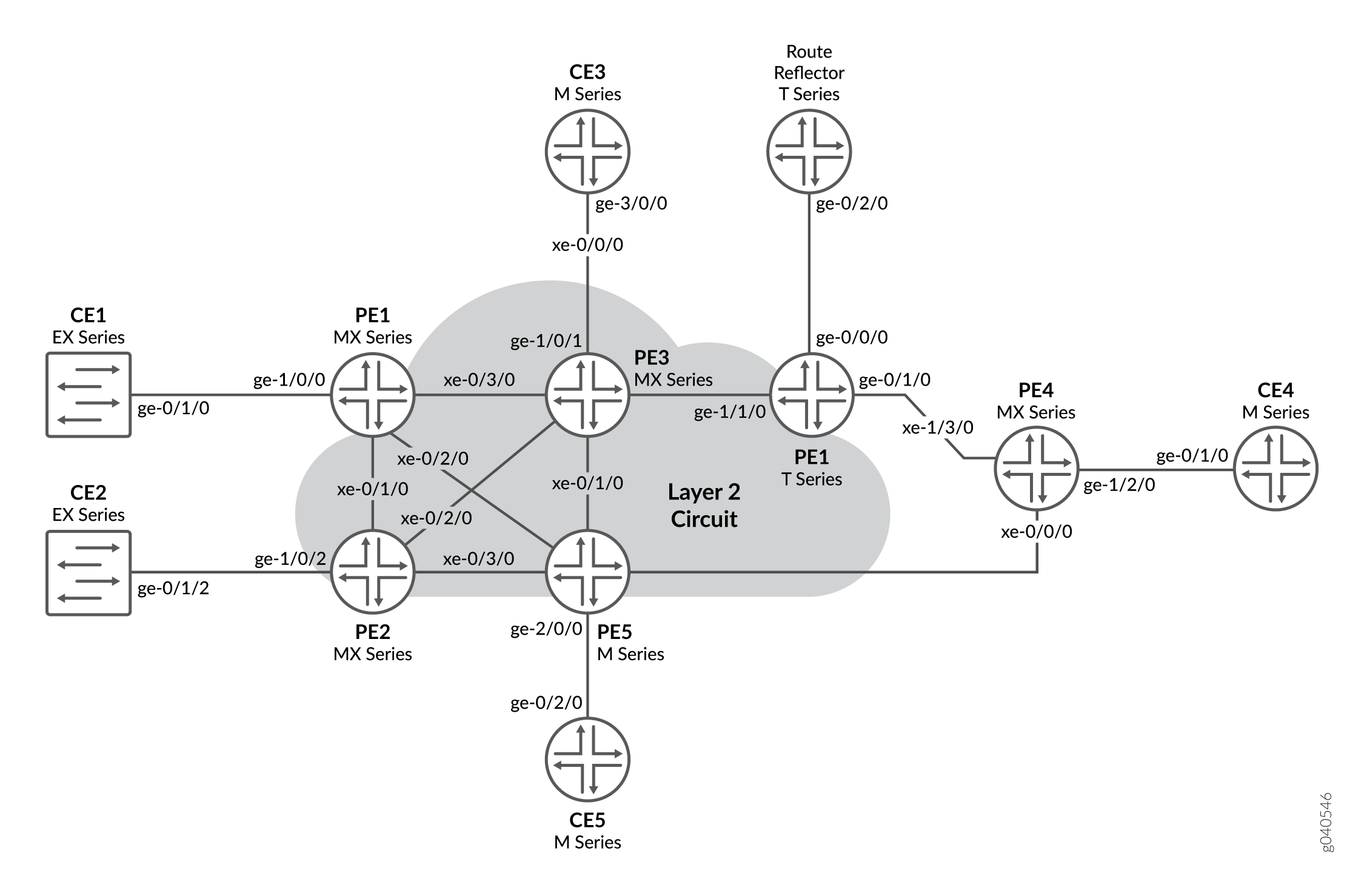
In Figure 1:
Local switching is used to switch traffic between Layer 2 circuit pseudowires from the different spoke PE routers.
The spoke PE routers are configured with the same virtual circuit ID and VPLS ID pair in a mesh group.
The spoke PE routers are configured in an LDP-signaled VPLS routing instance.
The layer 2 circuits are terminated into the LDP-based VPLS.
Configuration
To configure a single mesh group to terminate the Layer 2 circuits into an LDP-based VPLS, perform the following tasks:
Configuring the Spoke PE Routers
Step-by-Step Procedure
Configure a single mesh group to terminate all the Layer 2 circuit pseudowires and enable local switching between the pseudowires.
On Router PE1, configure the Layer 2 circuit by including the
l2circuitstatement at the[edit protocols]hierarchy level. Include theneighborstatement and specify the IPv4 address of the hub PE router. Also configure the logical interface by including theinterfacestatement and specify the interface connected to Router CE1.Configure the virtual circuit ID by including the
virtual-circuit-idstatement and specifying100as the ID value at the[edit protocols l2circuit neighbor 192.0.2.5 interface ge-1/0/0.0]hierarchy level.Configure the backup neighbor by including the
backup-neighborstatement and specifying the IPv4 address of the backup hub PE router. Router PE3 is the backup neighbor in this example. Also include thestandbystatement at the[edit protocols l2circuit neighbor 192.0.2.5 interface ge-1/0/0.0 backup-neighbor 192.0.2.3]hierarchy level.[edit protocols] l2circuit { neighbor 192.0.2.5 { interface ge-1/0/0.0 { virtual-circuit-id 100; backup-neighbor 192.0.2.3 { standby; } } } }On Router PE2, configure the Layer 2 circuit by including the
l2circuitstatement at the[edit protocols]hierarchy level. Include theneighborstatement and specify the IPv4 address of the hub PE router. Configure the logical interface by including theinterfacestatement and specifying the interface connected to Router CE2.Configure the virtual circuit ID by including the
virtual-circuit-idstatement and specifying100as the ID value at the[edit protocols l2circuit neighbor 192.0.2.5 interface ge-1/0/2.0]hierarchy level. Include theencapsulationstatement and specifyethernetas the type.Configure the backup neighbor by including the
backup-neighborstatement and specifying the IPv4 address of the backup hub PE router. Router PE3 is the backup neighbor in this example. Also include thestandbystatement at the[edit protocols l2circuit neighbor 192.0.2.5 interface ge-1/0/0.0 backup-neighbor 192.0.2.3]hierarchy level.[edit protocols] l2circuit { neighbor 192.0.2.5 { interface ge-1/0/2.0 { virtual-circuit-id 100; encapsulation-type ethernet; backup-neighbor 192.0.2.3 { standby; } } } }On Router PE4, configure the Layer 2 circuit by including the
l2circuitstatement at the[edit protocols]hierarchy level. Include theneighborstatement and specify the IPv4 address of the hub PE router. Configure the logical interface by including theinterfacestatement and specify the interface connected to Router CE4.Configure the virtual circuit ID by including the
virtual-circuit-idstatement and specifying100as the ID value at the[edit protocols l2circuit neighbor 192.0.2.5 interface ge-1/2/0.0]hierarchy level.Configure the backup neighbor by including the
backup-neighborstatement and specifying the IPv4 address of the backup hub PE router. Router PE3 is the backup neighbor in this example. Also include thestandbystatement at the[edit protocols l2circuit neighbor 192.0.2.5 interface ge-1/2/0.0 backup-neighbor 192.0.2.3]hierarchy level.[edit protocols] l2circuit { neighbor 192.0.2.5 { interface ge-1/2/0.0 { virtual-circuit-id 100; backup-neighbor 192.0.2.3 { standby; } } } }
Configuring the Hub PE Router
Step-by-Step Procedure
Configure a single mesh group to terminate all the Layer 2 circuit pseudowires and enable local switching between the pseudowires.
On Router PE3, configure the Gigabit Ethernet interface connected to Router CE3 by including the
encapsulationstatement and specifying theethernet-vplsoption. Also configure the logical interface by including thefamilystatement and specifying thevplsoption.[edit interfaces] ge-1/0/1 { encapsulation ethernet-vpls; unit 0 { family vpls; } }On Router PE3, configure the logical loopback interface by including the
familystatement and specifying theinetoption. Include theaddressstatement and specify the IPv4 address for the interface.[edit interfaces] lo0 { unit 0 { family inet { address 192.0.2.3/24; } } }On Router PE3, configure the LDP-based VPLS routing instance by including the
instance-typestatement at the[edit routing-instances H-VPLS]hierarchy level and specifying thevplsoption. Include theinterfacestatement and specify the Gigabit Ethernet interface connected to Router CE3.Configure the VPLS protocol by including the
vplsstatement at the[edit routing-instances H-VPLS protocols]hierarchy level. Include theno-tunnel-servicesstatement to enable the router to use an LSI interface.[edit routing-instances] H-VPLS { instance-type vpls; interface ge-1/0/1.0; protocols { vpls { no-tunnel-services; } } }On Router PE3, configure the mesh group by including the
mesh-groupstatement at the[edit routing-instances H-VPLS protocols vpls]hierarchy level and specifyingL2-Circuitsas the name of the group. Include thevpls-idstatement and specify100as the ID value. Include thelocal-switchingstatement to enable the router to switch traffic between the pseudowires.For each neighbor in the mesh group, include the
neighborstatement and specify the IPv4 address of the spoke PE router.[edit routing-instances H-VPLS protocols vpls] mesh-group L2-Circuits { vpls-id 100; <<< Same VPLS ID on all MTUs local-switching; << Local-switching enabled neighbor 192.0.2.1; <<MTU IP addresses neighbor 192.0.2.2; neighbor 192.0.2.4; }
Verification
Step-by-Step Procedure
On Router PE5, use the
show ldp neighborcommand to verify that LDP sessions have been created to each of the spoke PE routers.user@PE5# show ldp neighbor Address Interface Label space ID Hold time 192.0.2.1 lo0.0 192.0.2.1:0 33 192.0.2.2 lo0.0 192.0.2.2:0 37 192.0.2.4 lo0.0 192.0.2.4:0 39
On Router PE5, use the
show vpls connections extensivecommand to verify that the mesh group neighbor session isUp, that inbound and outbound labels have been assigned, that the VPLS ID is correct, and that the virtual tunnel interface is being used.user@PE5# show vpls connections extensive ... Instance: H-VPLS Number of local interfaces: 1 Number of local interfaces up: 1 Number of VE mesh-groups: 2 Number of VE mesh-groups up: 1 ge-2/0/0.0 Mesh-group interfaces: L2-Circuits State: Up ID: 2 vt-2/1/0.1048848 Intf - vpls H-VPLS neighbor 192.0.2.4 vpls-id 100 vt-2/1/0.1048849 Intf - vpls H-VPLS neighbor 192.0.2.2 vpls-id 100 vt-2/1/0.1048850 Intf - vpls H-VPLS neighbor 192.0.2.1 vpls-id 100 Mesh-group interfaces: __ves__ State: Dn ID: 0 Mesh-group connections: L2-Circuits Neighbor Type St Time last up # Up trans 192.0.2.4(vpls-id 100) rmt Up Jan 3 16:46:26 2010 1 Remote PE: 192.0.2.4, Negotiated control-word: No Incoming label: 800011, Outgoing label: 301088 Local interface: vt-2/1/0.1048848, Status: Up, Encapsulation: ETHERNET Description: Intf - vpls H-VPLS neighbor 192.0.2.4 vpls-id 100 Connection History: Jan 3 16:46:26 2010 status update timer Jan 3 16:46:26 2010 PE route changed Jan 3 16:46:26 2010 In lbl Update 800011 Jan 3 16:46:26 2010 Out lbl Update 301088 Jan 3 16:46:26 2010 In lbl Update 800011 Jan 3 16:46:26 2010 loc intf up vt-2/1/0.1048848 192.0.2.2(vpls-id 100) rmt Up Jan 3 16:46:26 2010 1 Remote PE: 192.0.2.2, Negotiated control-word: No Incoming label: 800010, Outgoing label: 301488 Local interface: vt-2/1/0.1048849, Status: Up, Encapsulation: ETHERNET Description: Intf - vpls H-VPLS neighbor 192.0.2.2 vpls-id 100 Connection History: Jan 3 16:46:26 2010 status update timer Jan 3 16:46:26 2010 PE route changed Jan 3 16:46:26 2010 In lbl Update 800010 Jan 3 16:46:26 2010 Out lbl Update 301488 Jan 3 16:46:26 2010 In lbl Update 800010 Jan 3 16:46:26 2010 loc intf up vt-2/1/0.1048849 192.0.2.1(vpls-id 100) rmt Up Jan 3 16:46:26 2010 1 Remote PE: 192.0.2.1, Negotiated control-word: No Incoming label: 800009, Outgoing label: 301296 Local interface: vt-2/1/0.1048850, Status: Up, Encapsulation: ETHERNET Description: Intf - vpls H-VPLS neighbor 192.0.2.1 vpls-id 100 Connection History: Jan 3 16:46:26 2010 status update timer Jan 3 16:46:26 2010 PE route changed Jan 3 16:46:26 2010 In lbl Update 800009 Jan 3 16:46:26 2010 Out lbl Update 301296 Jan 3 16:46:26 2010 In lbl Update 800009 Jan 3 16:46:26 2010 loc intf up vt-2/1/0.1048850