ON THIS PAGE
Example: Configuring BGP-Based H-VPLS Using Different Mesh Groups for Each Spoke Router
This example shows how to configure the hierarchical virtual private LAN service (H-VPLS) using different mesh groups to provide H-VPLS functionality and provides steps for verifying the configuration. This is one type of H-VPLS configuration possible in the Juniper Networks implementation. For information about the alternate type of configuration see Example: Configuring LDP-Based H-VPLS Using a Single Mesh Group to Terminate the Layer 2 Circuits.
Using mesh groups improves LDP-based VPLS control plane scalability and avoids the requirement for a full mesh of LDP sessions. This example uses BGP-based VPLS.
This example is organized into the following sections:
Requirements
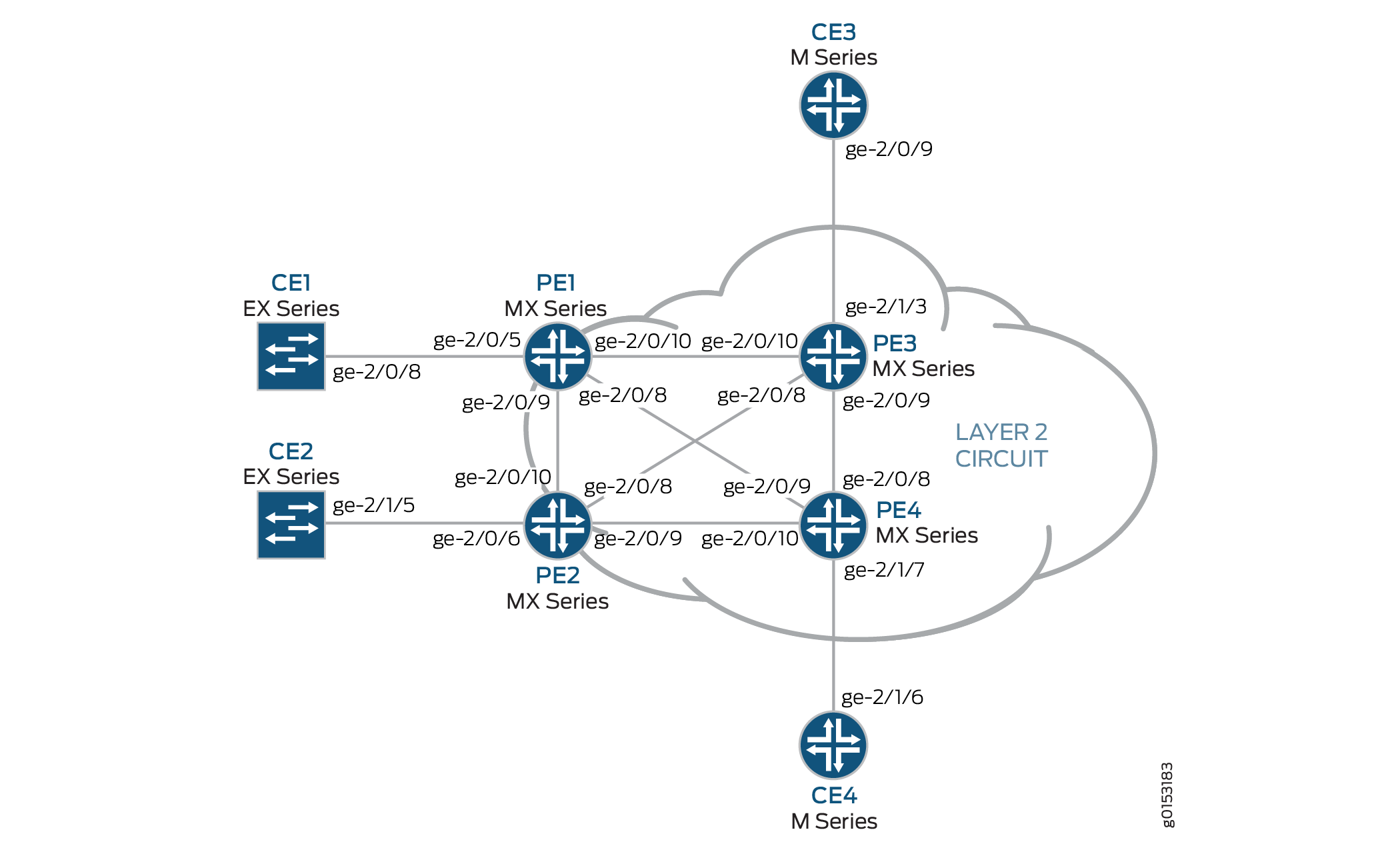
This example uses the following hardware components:
Four MX Series 5G Universal Routing Platforms for Router PE1, Router PE2, Router PE3, and Router PE4
One M Series Multiservice Edge Router for Router CE4
Two EX Series Ethernet Switches for Device CE1 and Device CE2
One J Series Services Router for Router CE3
Overview and Topology
Figure 1 shows the physical topology used in this example.
The following describes the base configuration used in this example:
Router PE1 and Router PE2 are configured as MTU devices.
Router PE3 and Router PE4 are configured as PE-r routers, each using an LDP-based VPLS routing instance.
The LDP and OSPF protocols are configured on all of the MTU devices and PE-r routers.
Core-facing interfaces are enabled with the MPLS address family.
Optionally, the VPLS routing instances can be configured on PE-r routers with the
no-tunnel-interfacestatement. This allows the routers to use a label-switched interface (LSI), which is useful if your routers do not have Tunnel Services PICs or built-in support for tunnel services.All of the routers are configured with loopback IP addresses.
BGP is configured on the PE-r routers. Optionally, you can configure route reflection. This is useful for scaling internal BGP (IBGP). The BGP configuration includes the
signalingstatement at the[edit protocols bgp group group-name family l2vpn]hierarchy level to support Layer 2 VPN signaling using BGP.
Figure 2 shows the logical topology used in this example.
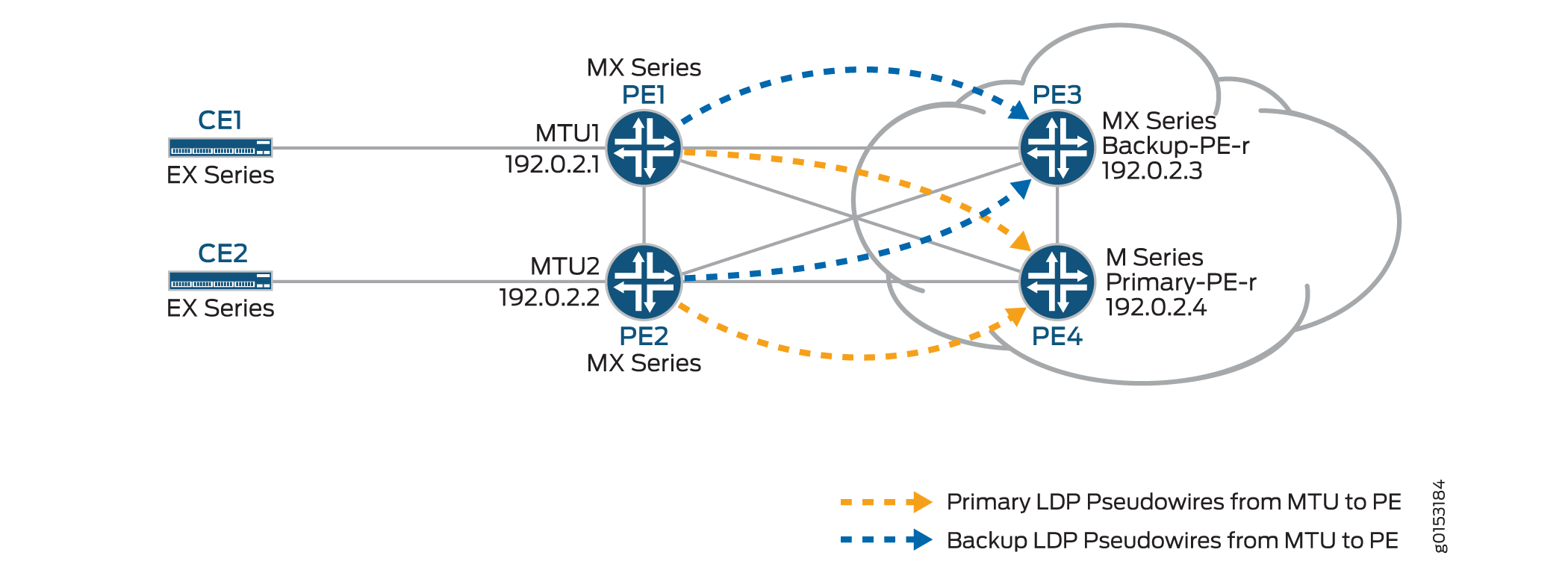
In Figure 2:
The MTU devices (Router PE1 and Router PE2) have Layer 2 circuit connections to the PE-r routers (Router PE3 and Router PE4). For redundancy, a backup neighbor is configured for the Layer 2 circuit connections to the PE-r routers.
The
l2circuitstatement in the[edit protocols]hierarchy is included on the MTU devices.A VPLS routing instance is configured on the PE-r routers.
In the VPLS routing instance on the PE-r routers, mesh groups are created to terminate the Layer 2 circuit pseudowires that originate at the MTU devices.
Each MTU device is configured with a different virtual circuit ID.
Each PE-r router’s mesh groups configuration includes VPLS ID values that match the virtual circuit IDs used on the MTU devices.
Configuration
To configure H-VPLS with different mesh groups for each spoke PE-r router using BGP-based VPLS, perform the following tasks:
Configuring the Spoke MTU PE Routers
Step-by-Step Procedure
On Router PE1, configure the Gigabit Ethernet interface connected to Router CE1. Include the
encapsulationstatement and specify theethernet-cccoption. Also configure the logical interface by including thefamilystatement and specifying thecccoption.[edit interfaces] ge-2/0/5 { encapsulation ethernet-ccc; unit 0 { family ccc; } }On Router PE1, configure the Layer 2 circuit by including the
neighborstatement and specifying the IP address of Router PE3 as the neighbor. Configure the Gigabit Ethernet logical interface by including thevirtual-circuit-idstatement and specifying100as the ID. Also configure a backup neighbor for the Layer 2 circuit by including thebackup-neighborstatement, specifying the loopback interface IP address of Router PE4 as the backup neighbor, and including thestandbystatement.[edit protocols] l2circuit { neighbor 192.0.2.3 { interface ge-2/0/5.0 { virtual-circuit-id 100; backup-neighbor 192.0.2.4 { # Backup H-VPLS PE router standby; } } }On Router PE2, configure the Gigabit Ethernet interface connected to Router CE2. Include the
encapsulationstatement and specify theethernet-cccoption. Also configure the logical interface by including thefamilystatement and specifying thecccoption.[edit interfaces] ge-2/0/6 { encapsulation ethernet-ccc; unit 0 { family ccc; } }On Router PE2, configure the Layer 2 circuit by including the
neighborstatement and specifying the IP address of Router PE3 as the neighbor. Configure the Gigabit Ethernet logical interface by including thevirtual-circuit-idstatement and specifying200as the ID. Configure the encapsulation by including theencapsulation-typestatement and specifying theethernetoption. Also configure a backup neighbor for the Layer 2 circuit by including thebackup-neighborstatement, specifying the loopback interface IP address of Router PE4 as the backup neighbor, and including thestandbystatement.[edit protocols] l2circuit { neighbor 192.0.2.3 { interface ge-1/0/2.0 { virtual-circuit-id 200; # different VC-ID encapsulation-type ethernet; # default encapsulation backup-neighbor 192.0.2.4 { standby; } } } }
Configuring the Hub PE (PE-r)
Step-by-Step Procedure
On Router PE3 (the primary hub), configure the Gigabit Ethernet interface connected to Router CE3. Include the
encapsulationstatement and specify theethernet-vplsoption. Also configure the logical interface by including thefamily vplsstatement.[edit interfaces] ge-2/0/0 { encapsulation ethernet-vpls; unit 0 { family vpls; } } lo0 { unit 0 { family inet { address 192.0.2.3/24; } } }On Router PE4 (the backup hub), configure the Gigabit Ethernet interface connected to Router CE4. Include the
encapsulationstatement and specify theethernet-vplsoption. Also configure the logical interface by including thefamily vplsstatement.[edit interfaces] ge-2/1/7 { encapsulation ethernet-vpls; unit 0 { description to_CE4; family vpls; } }lo0 { unit 0 { family inet { address 192.0.2.4/24; } } }On PE-r Router PE3, configure the BGP-based VPLS routing instance by including the
instance-typestatement at the[edit routing-instances H-VPLS]hierarchy level and specifying thevplsoption. Include theinterfacestatement and specify the Gigabit Ethernet interface connected to Router CE3. Configure a route distinguisher to ensure that the route advertisement is unique by including theroute-distinguisherstatement and specifying192.0.2.3:33as the value. Also configure the VPN routing and forwarding (VRF) route target to be included in the route advertisements to the other routers participating in the VPLS. To configure the VRF route target, include thevrf-targetstatement and specifytarget:64510:2as the value. Optionally, include theno-tunnel-servicesstatement to enable the use of LSI interfaces, which is useful if the device does not have tunnel services. Theno-tunnel-servicesstatement is omitted in this example. Optionally, you can include thesite-rangestatement to specify an upper limit on the maximum site identifier that can be accepted to allow a pseudowire to be brought up. Thesite-rangestatement is omitted in this example. We recommend using the default of 65,534.Configure the VPLS protocol and the mesh groups for each MTU PE device.
To configure the VPLS protocol, include the
vplsstatement at the[edit routing-instances H-VPLS protocols]hierarchy level. Include thesitestatement and specify a name for the site. Include theinterfacestatement and specify the Gigabit Ethernet interface connected to Device CE3.Configuring mesh groups under the VPLS instance terminates the Layer 2 circuit into the VPLS instance. To configure each mesh group, include the
mesh-groupstatement and specify the mesh group name. In this example, the mesh group name is the name of the MTU device associated with each mesh group. Include thevpls-idstatement and specify the ID that matches the virtual circuit ID configured in Configuring the Spoke MTU PE Routers. Also include theneighborstatement and specify the IP address of the spoke PE router associated with each mesh group. Optionally, include thelocal-switchingstatement if you are not using a full mesh of VPLS connections. Thelocal-switchingstatement is useful if you are configuring a single mesh group and terminating multiple Layer 2 circuit pseudowires into it. Thelocal-switchingstatement is omitted in this example.routing-instances { H-VPLS { instance-type vpls; interface ge-2/1/3.0; route-distinguisher 192.0.2.3:33; vrf-target target:64510:2; protocols { vpls { site pe3 { site-identifier 3; interface ge-2/1/3.0; } mesh-group pe1 { vpls-id 100; neighbor 192.0.2.1; } mesh-group pe2 { vpls-id 200; neighbor 192.0.2.2; } } } } }On PE-r Router PE4, configure a routing instance like the one on Router PE3.
routing-instances { H-VPLS { instance-type vpls; interface ge-2/1/7.0; route-distinguisher 192.0.2.4:44; vrf-target target:64510:2; protocols { vpls { site pe4 { site-identifier 4; interface ge-2/1/7.0; } mesh-group pe1 { vpls-id 100; neighbor 192.0.2.1; } mesh-group pe2 { vpls-id 200; neighbor 192.0.2.2; } } } } }
Verifying the H-VPLS Operation
Step-by-Step Procedure
This section describes the operational commands that you can use to validate that the H-VPLS is working as expected.
On Router PE1 and Router PE2, use the
show l2circuit connectionscommand to verify that the Layer 2 circuit to Router PE3 isUpand the Layer 2 circuit to Router PE4 is instandbymode.The output also shows the assigned label, virtual circuit ID, and the
ETHERNETencapsulation type.user@PE1> show l2circuit connections Layer-2 Circuit Connections: Legend for connection status (St) EI -- encapsulation invalid NP -- interface h/w not present MM -- mtu mismatch Dn -- down EM -- encapsulation mismatch VC-Dn -- Virtual circuit Down CM -- control-word mismatch Up -- operational VM -- vlan id mismatch CF -- Call admission control failure OL -- no outgoing label IB -- TDM incompatible bitrate NC -- intf encaps not CCC/TCC TM -- TDM misconfiguration BK -- Backup Connection ST -- Standby Connection CB -- rcvd cell-bundle size bad SP -- Static Pseudowire LD -- local site signaled down RS -- remote site standby RD -- remote site signaled down XX -- unknown Legend for interface status Up -- operational Dn -- down Neighbor: 192.0.2.3 Interface Type St Time last up # Up trans ge-2/0/5.0(vc 100) rmt Up Oct 18 15:55:07 2012 1 Remote PE: 192.0.2.3, Negotiated control-word: No Incoming label: 299840, Outgoing label: 800001 Negotiated PW status TLV: No Local interface: ge-2/0/5.0, Status: Up, Encapsulation: ETHERNET Neighbor: 192.0.2.4 Interface Type St Time last up # Up trans ge-2/0/5.0(vc 100) rmt STuser@PE2> show l2circuit connections Layer-2 Circuit Connections: Legend for connection status (St) EI -- encapsulation invalid NP -- interface h/w not present MM -- mtu mismatch Dn -- down EM -- encapsulation mismatch VC-Dn -- Virtual circuit Down CM -- control-word mismatch Up -- operational VM -- vlan id mismatch CF -- Call admission control failure OL -- no outgoing label IB -- TDM incompatible bitrate NC -- intf encaps not CCC/TCC TM -- TDM misconfiguration BK -- Backup Connection ST -- Standby Connection CB -- rcvd cell-bundle size bad SP -- Static Pseudowire LD -- local site signaled down RS -- remote site standby RD -- remote site signaled down XX -- unknown Legend for interface status Up -- operational Dn -- down Neighbor: 192.0.2.3 Interface Type St Time last up # Up trans ge-2/0/6.0(vc 200) rmt Up Oct 18 15:55:07 2012 1 Remote PE: 192.0.2.3, Negotiated control-word: No Incoming label: 299872, Outgoing label: 800002 Negotiated PW status TLV: No Local interface: ge-2/0/6.0, Status: Up, Encapsulation: ETHERNET Neighbor: 192.0.2.4 Interface Type St Time last up # Up trans ge-2/0/6.0(vc 200) rmt STOn Router PE1 and Router PE2, use the
show ldp neighborcommand to verify that the targeted LDP sessions have been created between the loopback interface to the primary and backup H-VPLS hub neighbors.user@PE1> show ldp neighbor Address Interface Label space ID Hold time 10.10.3.2 ge-2/0/9.0 192.0.2.2:0 13 10.10.1.2 ge-2/0/10.0 192.0.2.3:0 10 192.0.2.3 lo0.0 192.0.2.3:0 36 192.0.2.4 lo0.0 192.0.2.4:0 39 10.10.9.2 ge-2/0/8.0 192.0.2.4:0 14
user@PE2> show ldp neighbor Address Interface Label space ID Hold time 10.10.3.1 ge-2/0/10.0 192.0.2.1:0 12 10.10.5.2 ge-2/0/9.0 192.0.2.4:0 11 10.10.4.1 ge-2/0/8.0 192.0.2.3:0 11 192.0.2.3 lo0.0 192.0.2.3:0 39 192.0.2.4 lo0.0 192.0.2.4:0 38
On Router PE3 and Router PE4, use the
show vpls connectionscommand to verify that the VPLS connection status isUpfor both the LDP-based VPLS and the BGP-based VPLS Layer 2 circuits that are terminated.user@PE3> show vpls connections Layer-2 VPN connections: Legend for connection status (St) EI -- encapsulation invalid NC -- interface encapsulation not CCC/TCC/VPLS EM -- encapsulation mismatch WE -- interface and instance encaps not same VC-Dn -- Virtual circuit down NP -- interface hardware not present CM -- control-word mismatch -> -- only outbound connection is up CN -- circuit not provisioned <- -- only inbound connection is up OR -- out of range Up -- operational OL -- no outgoing label Dn -- down LD -- local site signaled down CF -- call admission control failure RD -- remote site signaled down SC -- local and remote site ID collision LN -- local site not designated LM -- local site ID not minimum designated RN -- remote site not designated RM -- remote site ID not minimum designated XX -- unknown connection status IL -- no incoming label MM -- MTU mismatch MI -- Mesh-Group ID not available BK -- Backup connection ST -- Standby connection PF -- Profile parse failure PB -- Profile busy RS -- remote site standby SN -- Static Neighbor LB -- Local site not best-site RB -- Remote site not best-site VM -- VLAN ID mismatch Legend for interface status Up -- operational Dn -- down Instance: H-VPLS BGP-VPLS State Local site: pe3 (3) connection-site Type St Time last up # Up trans 4 rmt Up Oct 18 15:58:39 2012 1 Remote PE: 192.0.2.4, Negotiated control-word: No Incoming label: 800267, Outgoing label: 800266 Local interface: vt-2/0/9.135266562, Status: Up, Encapsulation: VPLS Description: Intf - vpls H-VPLS local site 3 remote site 4 LDP-VPLS State Mesh-group connections: pe1 Neighbor Type St Time last up # Up trans 192.0.2.1(vpls-id 100) rmt Up Oct 18 15:55:07 2012 1 Remote PE: 192.0.2.1, Negotiated control-word: No Incoming label: 800001, Outgoing label: 299840 Negotiated PW status TLV: No Local interface: vt-2/0/10.135266560, Status: Up, Encapsulation: ETHERNET Description: Intf - vpls H-VPLS neighbor 192.0.2.1 vpls-id 100 Mesh-group connections: pe2 Neighbor Type St Time last up # Up trans 192.0.2.2(vpls-id 200) rmt Up Oct 18 15:55:07 2012 1 Remote PE: 192.0.2.2, Negotiated control-word: No Incoming label: 800002, Outgoing label: 299872 Negotiated PW status TLV: No Local interface: vt-2/0/8.135266561, Status: Up, Encapsulation: ETHERNET Description: Intf - vpls H-VPLS neighbor 192.0.2.2 vpls-id 200 user@PE4> show vpls connections Layer-2 VPN connections: Legend for connection status (St) EI -- encapsulation invalid NC -- interface encapsulation not CCC/TCC/VPLS EM -- encapsulation mismatch WE -- interface and instance encaps not same VC-Dn -- Virtual circuit down NP -- interface hardware not present CM -- control-word mismatch -> -- only outbound connection is up CN -- circuit not provisioned <- -- only inbound connection is up OR -- out of range Up -- operational OL -- no outgoing label Dn -- down LD -- local site signaled down CF -- call admission control failure RD -- remote site signaled down SC -- local and remote site ID collision LN -- local site not designated LM -- local site ID not minimum designated RN -- remote site not designated RM -- remote site ID not minimum designated XX -- unknown connection status IL -- no incoming label MM -- MTU mismatch MI -- Mesh-Group ID not available BK -- Backup connection ST -- Standby connection PF -- Profile parse failure PB -- Profile busy RS -- remote site standby SN -- Static Neighbor LB -- Local site not best-site RB -- Remote site not best-site VM -- VLAN ID mismatch Legend for interface status Up -- operational Dn -- down Instance: H-VPLS BGP-VPLS State Local site: pe4 (4) connection-site Type St Time last up # Up trans 3 rmt Up Oct 18 15:58:39 2012 1 Remote PE: 192.0.2.3, Negotiated control-word: No Incoming label: 800266, Outgoing label: 800267 Local interface: vt-2/0/8.17826050, Status: Up, Encapsulation: VPLS Description: Intf - vpls H-VPLS local site 4 remote site 3 LDP-VPLS State Mesh-group connections: pe1 Neighbor Type St Time last up # Up trans 192.0.2.1(vpls-id 100) rmt Up Oct 18 15:58:39 2012 1 Remote PE: 192.0.2.1, Negotiated control-word: No Incoming label: 800002, Outgoing label: 299856 Negotiated PW status TLV: No Local interface: vt-2/0/9.17826048, Status: Up, Encapsulation: ETHERNET Description: Intf - vpls H-VPLS neighbor 192.0.2.1 vpls-id 100 Mesh-group connections: pe2 Neighbor Type St Time last up # Up trans 192.0.2.2(vpls-id 200) rmt Up Oct 18 15:58:39 2012 1 Remote PE: 192.0.2.2, Negotiated control-word: No Incoming label: 800003, Outgoing label: 299888 Negotiated PW status TLV: No Local interface: vt-2/0/10.17826049, Status: Up, Encapsulation: ETHERNET Description: Intf - vpls H-VPLS neighbor 192.0.2.2 vpls-id 200On Router PE3 and Router PE4, use the
show vpls floodcommand to verify that the H-VPLS PE router created a flood group for each spoke PE site.user@PE3> show vpls flood Name: H-VPLS CEs: 1 VEs: 3 Flood Routes: Prefix Type Owner NhType NhIndex 0x300cc/51 FLOOD_GRP_COMP_NH __ves__ comp 1376 0x300cf/51 FLOOD_GRP_COMP_NH __all_ces__ comp 744 0x300d5/51 FLOOD_GRP_COMP_NH pe1 comp 1702 0x300d3/51 FLOOD_GRP_COMP_NH pe2 comp 1544 0x30001/51 FLOOD_GRP_COMP_NH __re_flood__ comp 740
user@PE4> show vpls flood Name: H-VPLS CEs: 1 VEs: 3 Flood Routes: Prefix Type Owner NhType NhIndex 0x300d1/51 FLOOD_GRP_COMP_NH __ves__ comp 1534 0x300d0/51 FLOOD_GRP_COMP_NH __all_ces__ comp 753 0x300d6/51 FLOOD_GRP_COMP_NH pe1 comp 1378 0x300d4/51 FLOOD_GRP_COMP_NH pe2 comp 1695 0x30002/51 FLOOD_GRP_COMP_NH __re_flood__ comp 750
On Router PE3 and Router PE4, use the
show vpls mac-tablecommand to verify that MAC addresses of the CE devices have been learned.user@PE3> show vpls mac-table MAC flags (S -static MAC, D -dynamic MAC, L -locally learned, C -Control MAC SE -Statistics enabled, NM -Non configured MAC, R -Remote PE MAC) Routing instance : H-VPLS Bridging domain : __H-VPLS__, VLAN : NA MAC MAC Logical NH RTR address flags interface Index ID 00:21:59:0f:35:32 D vt-2/0/8.135266560 00:21:59:0f:35:33 D ge-2/1/3.0 00:21:59:0f:35:d4 D vt-2/0/9.135266561 00:21:59:0f:35:d5 D vt-2/0/10.135266562user@PE4> show vpls mac-table MAC flags (S -static MAC, D -dynamic MAC, L -locally learned, C -Control MAC SE -Statistics enabled, NM -Non configured MAC, R -Remote PE MAC) Logical system : PE4 Routing instance : H-VPLS Bridging domain : __H-VPLS__, VLAN : NA MAC MAC Logical NH RTR address flags interface Index ID 00:21:59:0f:35:32 D vt-2/0/8.17826050 00:21:59:0f:35:33 D vt-2/0/9.17826050 00:21:59:0f:35:d4 D vt-2/0/10.17826050 00:21:59:0f:35:d5 D ge-2/1/7.0Make sure that the CE devices can ping each other.
user@CE1> ping 10.255.14.219 # ping sent from CE1 CE4 PING 10.255.14.219 (10.255.14.219): 56 data bytes 64 bytes from 10.255.14.219: icmp_seq=0 ttl=64 time=10.617 ms 64 bytes from 10.255.14.219: icmp_seq=1 ttl=64 time=9.224 ms ^C --- 10.255.14.219 ping statistics --- 2 packets transmitted, 2 packets received, 0% packet loss round-trip min/avg/max/stddev = 9.224/9.921/10.617/0.697 ms
user@CE2> ping 10.255.14.218 # ping sent from CE2 to CE3 PING 10.255.14.218 (10.255.14.218): 56 data bytes 64 bytes from 10.255.14.218: icmp_seq=0 ttl=64 time=1.151 ms 64 bytes from 10.255.14.218: icmp_seq=1 ttl=64 time=0.674 ms ^C --- 10.255.14.218 ping statistics --- 2 packets transmitted, 2 packets received, 0% packet loss round-trip min/avg/max/stddev = 0.674/0.913/1.151/0.238 ms
Check the relevant routing tables.
user@PE1> show route table l2circuit.0 l2circuit.0: 4 destinations, 4 routes (4 active, 0 holddown, 0 hidden) + = Active Route, - = Last Active, * = Both 192.0.2.3:NoCtrlWord:5:100:Local/96 *[L2CKT/7] 00:12:16, metric2 1 > to 10.10.1.2 via ge-2/0/10.0 192.0.2.3:NoCtrlWord:5:100:Remote/96 *[LDP/9] 00:12:16 Discard 192.0.2.4:NoCtrlWord:5:100:Local/96 *[L2CKT/7] 00:12:10, metric2 1 > to 10.10.9.2 via ge-2/0/8.0 192.0.2.4:NoCtrlWord:5:100:Remote/96 *[LDP/9] 00:12:15 Discarduser@PE2> show route table l2circuit.0 l2circuit.0: 4 destinations, 4 routes (4 active, 0 holddown, 0 hidden) + = Active Route, - = Last Active, * = Both 192.0.2.3:NoCtrlWord:5:200:Local/96 *[L2CKT/7] 00:13:13, metric2 1 > to 10.10.4.1 via ge-2/0/8.0 192.0.2.3:NoCtrlWord:5:200:Remote/96 *[LDP/9] 00:13:13 Discard 192.0.2.4:NoCtrlWord:5:200:Local/96 *[L2CKT/7] 00:13:13, metric2 1 > to 10.10.5.2 via ge-2/0/9.0 192.0.2.4:NoCtrlWord:5:200:Remote/96 *[LDP/9] 00:13:13 Discard user@PE3> show route table H-VPLS.l2vpn.0 H-VPLS.l2vpn.0: 2 destinations, 2 routes (2 active, 0 holddown, 0 hidden) + = Active Route, - = Last Active, * = Both 192.0.2.3:33:3:1/96 *[L2VPN/170/-101] 03:19:26, metric2 1 Indirect 192.0.2.4:44:4:1/96 *[BGP/170] 03:15:45, localpref 100, from 192.0.2.4 AS path: I, validation-state: unverified > to 10.10.6.2 via ge-2/0/9.0 user@PE4> show route table H-VPLS.l2vpn.0 H-VPLS.l2vpn.0: 2 destinations, 2 routes (2 active, 0 holddown, 0 hidden) + = Active Route, - = Last Active, * = Both 192.0.2.3:33:3:1/96 *[BGP/170] 03:21:17, localpref 100, from 192.0.2.3 AS path: I, validation-state: unverified > to 10.10.6.1 via ge-2/0/9.0 192.0.2.4:44:4:1/96 *[L2VPN/170/-101] 03:17:47, metric2 1 Indirect
Results
The configuration and verification parts of this example have been completed. The following section is for your reference.
The relevant sample configuration for Router PE1 follows.
Router PE1
interfaces {
ge-2/0/5 {
encapsulation ethernet-ccc;
unit 0 {
description to_CE1;
family ccc;
}
}
ge-2/0/8 {
unit 0 {
description to_PE4;
family inet {
address 10.10.9.1/30;
}
family mpls;
}
}
ge-2/0/9 {
unit 0 {
description to_PE2;
family inet {
address 10.10.3.1/30;
}
family mpls;
}
}
ge-2/0/10 {
unit 0 {
description to_PE3;
family inet {
address 10.10.1.1/30;
}
family mpls;
}
}
lo0 {
unit 0 {
family inet {
address 192.0.2.1/24;
}
}
}
}
protocols {
mpls {
interface ge-2/0/8.0;
interface ge-2/0/9.0;
interface ge-2/0/10.0;
}
ospf {
traffic-engineering;
area 0.0.0.0 {
interface lo0.0 {
passive;
}
interface ge-2/0/8.0;
interface ge-2/0/9.0;
interface ge-2/0/10.0;
}
}
ldp {
interface ge-2/0/8.0;
interface ge-2/0/9.0;
interface ge-2/0/10.0;
interface lo0.0;
}
l2circuit {
neighbor 192.0.2.3 {
interface ge-2/0/5.0 {
virtual-circuit-id 100;
backup-neighbor 192.0.2.4 {
standby;
}
}
}
}
}
The relevant sample configuration for Router PE2 follows.
Router PE2
interfaces {
ge-2/0/6 {
encapsulation ethernet-ccc;
unit 0 {
description to_CE2;
family ccc;
}
}
ge-2/0/8 {
unit 0 {
description to_PE3;
family inet {
address 10.10.4.2/30;
}
family mpls;
}
}
ge-2/0/9 {
unit 0 {
description to_PE4;
family inet {
address 10.10.5.1/30;
}
family mpls;
}
}
ge-2/0/10 {
unit 0 {
description to_PE1;
family inet {
address 10.10.3.2/30;
}
family mpls;
}
}
lo0 {
unit 0 {
family inet {
address 192.0.2.2/24;
}
}
}
}
protocols {
mpls {
interface ge-2/0/8.0;
interface ge-2/0/9.0;
interface ge-2/0/10.0;
}
ospf {
traffic-engineering;
area 0.0.0.0 {
interface lo0.0 {
passive;
}
interface ge-2/0/8.0;
interface ge-2/0/9.0;
interface ge-2/0/10.0;
}
}
ldp {
interface ge-2/0/8.0;
interface ge-2/0/9.0;
interface ge-2/0/10.0;
interface lo0.0;
}
l2circuit {
neighbor 192.0.2.3 {
interface ge-2/0/6.0 {
virtual-circuit-id 200;
backup-neighbor 192.0.2.4 {
standby;
}
}
}
}
}
The relevant sample configuration for Router PE3 follows.
Router PE3
interfaces {
ge-2/0/8 {
unit 0 {
description to_PE2;
family inet {
address 10.10.4.1/30;
}
family mpls;
}
}
ge-2/0/9 {
unit 0 {
description to_PE4;
family inet {
address 10.10.6.1/30;
}
family mpls;
}
}
ge-2/0/10 {
unit 0 {
description to_PE1;
family inet {
address 10.10.1.2/30;
}
family mpls;
}
}
ge-2/1/3 {
encapsulation ethernet-vpls;
unit 0 {
description to_CE3;
family vpls;
}
}
lo0 {
unit 0{
family inet {
address 192.0.2.3/24;
}
}
}
}
protocols {
mpls {
interface ge-2/0/8.0;
interface ge-2/0/9.0;
interface ge-2/0/10.0;
}
bgp {
group internal-peers {
type internal;
local-address 192.0.2.3;
family l2vpn {
signaling;
}
neighbor 192.0.2.4;
}
}
ospf {
traffic-engineering;
area 0.0.0.0 {
interface lo0.0 {
passive;
}
interface ge-2/0/8.0;
interface ge-2/0/9.0;
interface ge-2/0/10.0;
}
}
ldp {
interface ge-2/0/8.0;
interface ge-2/0/9.0;
interface ge-2/0/10.0;
interface lo0.0;
}
}
routing-instances {
H-VPLS {
instance-type vpls;
interface ge-2/1/3.0;
route-distinguisher 192.0.2.3:33;
vrf-target target:64510:2;
protocols {
vpls {
site pe3 {
site-identifier 3;
interface ge-2/1/3.0;
}
mesh-group pe1 {
vpls-id 100;
neighbor 192.0.2.1;
}
mesh-group pe2 {
vpls-id 200;
neighbor 192.0.2.2;
}
}
}
}
}
routing-options {
autonomous-system 64510;
}
The relevant sample configuration for Router PE4 follows.
Router PE4
interfaces {
ge-2/0/8 {
unit 0 {
description to_PE3;
family inet {
address 10.10.6.2/30;
}
family mpls;
}
}
ge-2/0/9 {
unit 0 {
description to_PE1;
family inet {
address 10.10.9.2/30;
}
family mpls;
}
}
ge-2/0/10 {
unit 0 {
description to_PE2;
family inet {
address 10.10.5.2/30;
}
family mpls;
}
}
ge-2/1/7 {
encapsulation ethernet-vpls;
unit 0 {
description to_CE4;
family vpls;
}
}
lo0 {
    unit 0 {
        family inet {
            address 192.0.2.4/24;
        }
    }
}
}
protocols {
mpls {
interface ge-2/0/8.0;
interface ge-2/0/9.0;
interface ge-2/0/10.0;
}
bgp {
group internal-peers {
type internal;
local-address 192.0.2.4;
family l2vpn {
signaling;
}
neighbor 192.0.2.3;
}
}
ospf {
traffic-engineering;
area 0.0.0.0 {
interface lo0.0 {
passive;
}
interface ge-2/0/8.0;
interface ge-2/0/9.0;
interface ge-2/0/10.0;
}
}
ldp {
interface ge-2/0/8.0;
interface ge-2/0/9.0;
interface ge-2/0/10.0;
interface lo0.0;
}
}
routing-instances {
    H-VPLS {
        instance-type vpls;
        interface ge-2/1/7.0;
        route-distinguisher 192.0.2.4:44;
        vrf-target target:64510:2;
        protocols {
            vpls {
                site pe4 {
                    site-identifier 4;
                    interface ge-2/1/7.0;
                }
                mesh-group pe1 {
                    vpls-id 100;
                    neighbor 192.0.2.1;
                }
                mesh-group pe2 {
                    vpls-id 200;
                    neighbor 192.0.2.2;
                }
            }
        }
    }
}
routing-options {
autonomous-system 64510;
}
The relevant sample configuration for Device CE1 follows.
Router CE1
interfaces {
    ge-2/0/8 {
        unit 0 {
            description to_PE1;
            family inet {
                address 172.16.0.1/24;
            }
        }
    }
    lo0 {
        unit 0{
            family inet {
                address 10.255.14.214/32;
            }
        }
    }
}
protocols {
    ospf {
        area 0.0.0.0 {
            interface lo0.0 {
                passive;
            }
            interface ge-2/0/8.0;
        }
    }
}
The relevant sample configuration for Device CE2 follows.
Router CE2
interfaces {
    ge-2/1/5 {
        unit 0 {
            description to_PE2;
            family inet {
                address 172.16.0.2/24;
            }
        }
    }
    lo0 {
        unit 0{
            family inet {
                address 10.255.14.215/32;
            }
        }
    }
}
protocols {
    ospf {
        area 0.0.0.0 {
            interface lo0.0 {
                passive;
            }
            interface ge-2/1/5.0;
        }
    }
}
The relevant sample configuration for Device CE3 follows.
Router CE3
interfaces {
    ge-2/0/9 {
        unit 0 {
            description to_PE3;
            family inet {
                address 172.16.0.3/24;
            }
        }
    }
    lo0 {
        unit 0 {
            family inet {
                address 10.255.14.218/32;
            }
        }
    }
}
protocols {
    ospf {
        area 0.0.0.0 {
            interface lo0.0 {
                passive;
            }
            interface ge-2/0/9.0;
        }
    }
}
The relevant sample configuration for Device CE4 follows.
Router CE4
interfaces {
    ge-2/1/6 {
        unit 0 {
            description to_PE4;
            family inet {
                address 172.16.0.4/24;
            }
        }
    }
    lo0 {
        unit 0{
            family inet {
                address 10.255.14.219/32;
            }
        }
    }
}
protocols {
    ospf {
        area 0.0.0.0 {
            interface lo0.0 {
                passive;
            }
            interface ge-2/1/6.0;
        }
    }
}