IP Packet Reassembly on Inline Service Interfaces
IP Packet Fragment Reassembly for L2TP Overview
You can configure inline service interfaces on MX Series routers with MPCs to support reassembly of fragmented IP packets for an L2TP connection. When packets are transmitted over an L2TP connection, the packets may be fragmented during transmission and need to be reassembled before they are processed further. Efficient reassembly is important for network throughput, scalability, and graceful response to congestion.
Fragmentation of IP packets for transmission and the need to reassemble the IP packets at a destination is a feature of how Layer 2 (the frame layer) and Layer 3 (the packet layer) operate. The maximum size of a frame, set by the Maximum Transmission Unit (MTU) value, and the maximum size of a packet are determined independently. Typically the packet size can far exceed the MTU size defined for the outgoing connection. If the packet size (data plus IP and other headers) exceeds the configured frame size (usually set by the transport medium limits), the packet must be fragmented and split across multiple frames for transmission.
Frames are always processed immediately, when they arrive (if error-free), but packet fragments cannot be processed until the whole packet has been reassembled. Each packet fragment inside a frame series, except the last packet fragment, has the more fragments (MF) IP header bit set, indicating that this packet is part of a whole. The last packet fragment inside a frame does not have this MF bit set and therefore ends the fragment sequence. After all of the fragments of a packet have arrived, the entire packet can be reassembled.
In an L2TP connection, packets are transmitted between the L2TP Access Concentrator (LAC) and the L2TP Network Server (LNS). For an IP packet being transmitted over an L2TP connection, the packet is fragmented at one of the following locations:
-
At the LAC for traffic destined for the LNS
-
At the LNS for traffic destined for the LAC
-
At an intermediate router when the LAC and LNS are not directly connected and the MTU size on the router is less than that on the LAC or LNS.
IP reassembly parameters configured on inline service interfaces of the LAC and the LNS determine how the fragments are reassembled on these interfaces to ensure efficient reassembly over an L2TP connection. Figure 1 shows IP fragmentation and reassembly for inbound subscriber traffic in a simplified L2TP network.
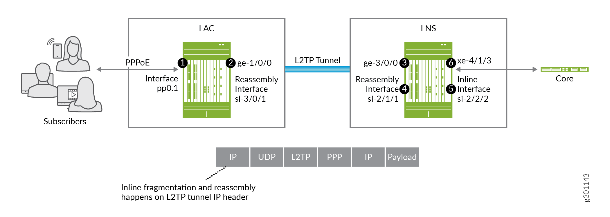
Traffic inbound to the core:
-
Subscriber traffic arrives on the LAC subscriber-facing interface, pp0.1, in the packet format [MAC] [PPPoE] [PPP] [IP] [Payload]. The PPPoE header is stripped off and the L2TP tunnel header is added, creating the tunnel packet, [IP] [UDP] [L2TP] [PPP] [IP] [Payload].
-
The packet is sent out the LAC’s peer WAN interface, ge-1/0/0, on the L2TP tunnel. If the packet size is larger than the MTU of the WAN interface, the packet is fragmented on the L2TP tunnel header. The LAC then sends the fragments to the LNS.
-
When the fragments arrive on the LNS peer WAN interface, ge-3/0/0, a route lookup steers the fragments to the LNS reassembly inline interface, si-2/1/1.
-
The fragments are reassembled on interface si-2/1/1 and the packet is sent to the LNS inline interface, si-2/2/2.
-
L2TP decapsulates the L2TP tunnel header and the PPP header on the si-2/2/2 inline interface, leaving the IP header and the payload. A route lookup on the IP header sends the packet to the LNS’s core-facing interface, xe-4/1/3.
-
The packet is sent out the core-facing interface, xe-4/1/3.
Figure 2 shows IP fragmentation and reassembly for outbound subscriber traffic in a simplified L2TP network.
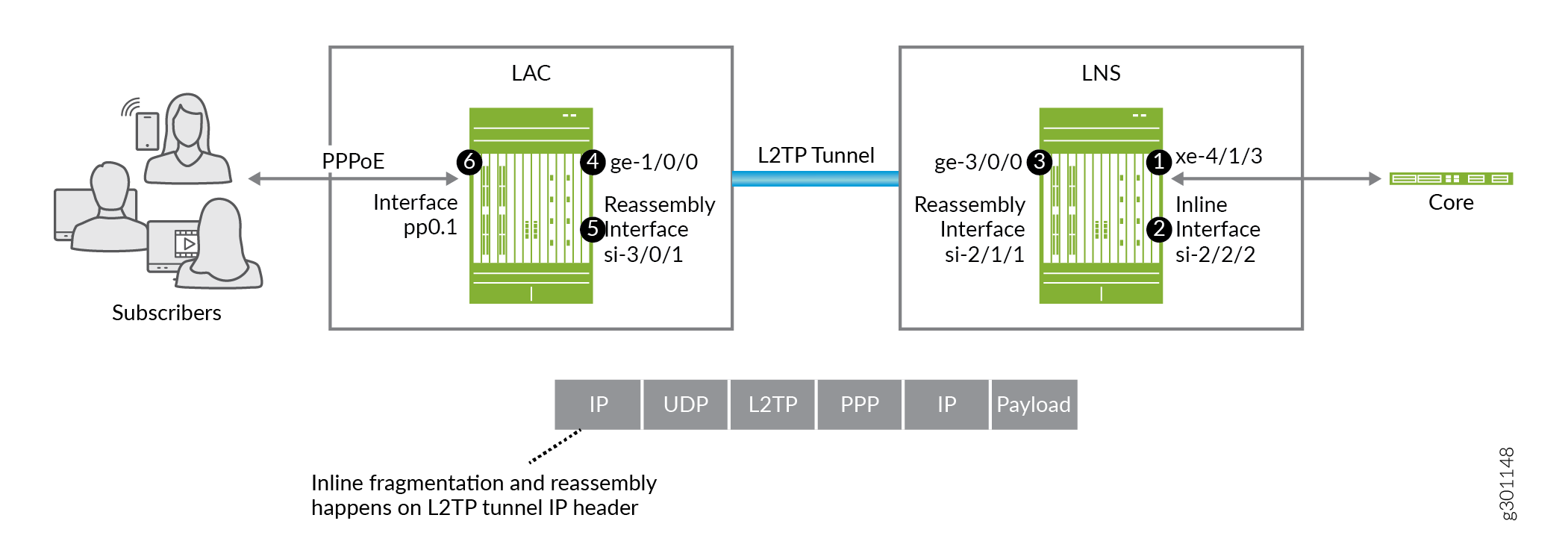
Traffic outbound to subscribers:
-
Subscriber traffic arrives on the LNS core-facing interface, xe-4/1/3. A route lookup steers the packet to the LNS inline interface, si-2/2/2.
-
On interface si-2/2/2, L2TP encapsulates the packet with the L2TP header and PPP header. and then creates the L2TP tunnel packet, [IP] [UDP] [L2TP] [PPP] [IP] [Payload].
-
Route lookup on the L2TP tunnel IP header sends the packet to the LNS’s peer WAN interface, ge-3/0/0. If the packet size is larger than the MTU of the WAN interface, the packet is fragmented on the L2TP tunnel header. The LNS then sends the fragments to the LAC.
-
When the fragments arrive on the LAC peer WAN interface, ge-1/0/0, a route lookup steers the fragments to the LAC reassembly inline interface, si-3/0/1.
-
The fragments are reassembled on this interface and the packet is sent to the subscriber-facing interface, pp0.1.
-
L2TP decapsulates the L2TP tunnel header on the pp0.1 inline interface, leaving [PPP] [IP] [Payload]. Then PPPoE and MAC encapsulation takes place on the packet. The packet, now consisting of [MAC] [PPPoE] [PPP] [IP] [Payload] is sent out the access interface to the subscriber.
Configuring IP Inline Reassembly for L2TP
This procedure shows how to configure a service interface on a LAC or LNS to reassemble fragmented IP packets. This example creates a service set that configures the IP reassembly parameters for L2TP fragments. The service set is then associated with the L2TP service.
Before you configure inline IP reassembly, be sure you have:
Configured L2TP.
Configured a valid service interface on the LAC or LNS.
To configure inline IP reassembly: